EP0880032B1 - Vorrichtung zur Erstellung eines Bildes sowie Verfahren und Vorrichtung zur Entfernungsmessung - Google Patents
Vorrichtung zur Erstellung eines Bildes sowie Verfahren und Vorrichtung zur Entfernungsmessung Download PDFInfo
- Publication number
- EP0880032B1 EP0880032B1 EP98109074A EP98109074A EP0880032B1 EP 0880032 B1 EP0880032 B1 EP 0880032B1 EP 98109074 A EP98109074 A EP 98109074A EP 98109074 A EP98109074 A EP 98109074A EP 0880032 B1 EP0880032 B1 EP 0880032B1
- Authority
- EP
- European Patent Office
- Prior art keywords
- image
- ccd
- imaging apparatus
- road
- white lines
- Prior art date
- Legal status (The legal status is an assumption and is not a legal conclusion. Google has not performed a legal analysis and makes no representation as to the accuracy of the status listed.)
- Expired - Lifetime
Links
Images


Classifications
-
- G—PHYSICS
- G06—COMPUTING OR CALCULATING; COUNTING
- G06V—IMAGE OR VIDEO RECOGNITION OR UNDERSTANDING
- G06V20/00—Scenes; Scene-specific elements
- G06V20/50—Context or environment of the image
- G06V20/56—Context or environment of the image exterior to a vehicle by using sensors mounted on the vehicle
- G06V20/588—Recognition of the road, e.g. of lane markings; Recognition of the vehicle driving pattern in relation to the road
-
- G—PHYSICS
- G01—MEASURING; TESTING
- G01S—RADIO DIRECTION-FINDING; RADIO NAVIGATION; DETERMINING DISTANCE OR VELOCITY BY USE OF RADIO WAVES; LOCATING OR PRESENCE-DETECTING BY USE OF THE REFLECTION OR RERADIATION OF RADIO WAVES; ANALOGOUS ARRANGEMENTS USING OTHER WAVES
- G01S11/00—Systems for determining distance or velocity not using reflection or reradiation
- G01S11/12—Systems for determining distance or velocity not using reflection or reradiation using electromagnetic waves other than radio waves
-
- G—PHYSICS
- G06—COMPUTING OR CALCULATING; COUNTING
- G06V—IMAGE OR VIDEO RECOGNITION OR UNDERSTANDING
- G06V20/00—Scenes; Scene-specific elements
- G06V20/50—Context or environment of the image
- G06V20/56—Context or environment of the image exterior to a vehicle by using sensors mounted on the vehicle
- G06V20/58—Recognition of moving objects or obstacles, e.g. vehicles or pedestrians; Recognition of traffic objects, e.g. traffic signs, traffic lights or roads
Definitions
- the present invention relates to an imaging apparatus which, in order to grasp the status of a road, images an object using a plurality of CCDs to detect an obstacle and the like on the road, and a distance measurement apparatus for calculating the distance between the car and the object.
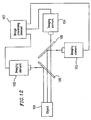
- a conventional distance measurement apparatus is described in Japanese Laid-Open Publication No. 8-75454, for example. This conventional distance measurement apparatus will be described with reference to Figure 12 .
- the conventional distance measurement apparatus includes imaging elements 102 , 103 , and 104 , half mirrors 105 and 106, and an image processing element 107.
- the distance measurement apparatus images an object 101 using the imaging elements 102, 103 , and 104 so that the horizontal or vertical parallax between the adjacent imaging elements constitutes several pixels.
- the image processing element 107 receives a plurality of imaged video signals simultaneously to synthesize video signals on the same horizontal or vertical lines among the plurality of video signals and thus to produce an image for parallax detection.
- the parallax is obtained from the tilt of a straight line formed by points corresponding to the edges of the object 101 , and then the distance between the car and the object 101 is calculated based on the parallax.
- the conventional distance measurement apparatus with the above configuration is disadvantageous in the following points. Since the conventional distance measurement apparatus includes a plurality of imaging elements, the following problems arise. It is not easy to accommodate such an apparatus in a small space inside a car. Two optical systems are required, increasing the production cost. The resolution of each pixel is as small as about 50 cm for an object located about 100 m distant from the car, which fails to provide a sufficient distance measurement performance. The plurality of optical systems need to be aligned with one another with high precision, resulting in the difficulty in adjustment and an increase in maintenance cost.
- US 5132802 which describes high contrast imaging apparatus, intended for detecting camouflaged objects.
- the apparatus is said to include at least two image pick-up elements, particularly CCD cameras, whose output signals are fed to a signal processing arrangement whereby they are combined and displayed to the user as a combined image.
- respective optical filters are disposed in front of the image pick-up elements so as to cause each image pick-up element to have its maximum sensitivity in a different spectral range.
- the imaging apparatus of the present invention includes:
- the imaging apparatus further includes a wavelength selective optical element on an optical path from the lens to at least one of the first and second CCDs.
- the wavelength selective optical element is an infrared filter.
- the half mirror also functions as the wavelength selective optical element which selectively reflects infrared radiation.
- the half mirror also functions as the wavelength selective optical element which selectively transmits infrared radiation.
- the imaging apparatus further includes a magnifying lens on an optical path from the lens to at least one of the first and second CCDs.
- the imaging apparatus further includes a circuit for detecting a correlation between the normal image and the inverted image.
- the invention described herein makes possible the advantages of providing a small-size high-precision imaging apparatus with easy maintenance using an optical system for detecting an obstacle on a road and the like.
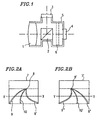
- Figure 1 is a schematic view of an optical system for an imaging apparatus of Example 1 according to the present invention.
- the optical system in this example includes a lens 1 , a half mirror 2 , a first CCD 3 , a second CCD 4 , and a housing 5 .
- the lens 1 , the half mirror 2 , and the second CCD 4 are arranged coaxially, while the first CCD 3 is arranged along an axis of light reflected by the half mirror 2 .
- a color filter 6 may be disposed between the half mirror 2 and the first CCD 3 or the second CCD 4 , if required.
- Part of light incident on the lens 1 is reflected by the half mirror 2 to be focused as a mirror image on the first CCD 3 disposed along the axis of the reflected light.
- the remainder of the incident light which has passed through the half mirror 2 is focused as a normal image on the second CCD 4 .
- Figure 2A illustrates a normal image 7 obtained on the second CCD 4 .
- a fade-out point 8 in the normal image 7 is an infinite point on a road.
- Left and right white lines 9 and 9' on the road intersect with each other at the fade-out point 8 as the infinite point.
- a broken line 10 on the road also intersects with the white lines 9 and 9' at the fade-out point 8 .
- FIG 2B illustrates a mirror image 7' of the normal image 7 obtained on the first CCD 3 .
- a fade-out point 8 ' in the mirror image 7' is an infinite point on the road.
- Left and right white lines 9'' and 9''' intersect with each other at the fade-out point 8' as the infinite point.
- a broken line 10' on the road also intersects with the white lines 9'' and 9''' at the fade-out point 8'.
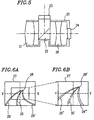
- Figures 3A and 3B schematically show changes in brightness signals along a raster X-X in Figure 2A and a raster Y-Y in Figure 2B, respectively.
- the left white line 9 , the broken line 10 , and the right white line 9' on the road are positioned in the order from left to right in the normal image 7 obtained on the second CCD 4
- the signal X-X of Figure 3A represents the change in brightness in the above order.
- the rising of the brightness of the white line is used for the detection of the white line 9
- the left edge of the white line is detected.
- the left edges of the broken line 10 and the right white line 9' are detected in this order, thus continuously detecting the white lines along the raster. In this way, the geometry of the road using the left edges of the white lines is recognized.
- the right white line 9''' , the broken line 10' , and the left white line 9'' on the road are positioned in the order from left to right in the mirror image 7' obtained on the first CCD 3 , and the signal Y-Y of Figure 3B represents the change in brightness in the above order.
- the rising of the brightness of the white line is used for the detection of the white line 9''' as in Figure 3A .
- the right edge of the white line is detected.
- the right edges of the broken line 10' and the left white line 9" are detected in this order, thus continuously detecting the white lines along the raster. In this way, the geometry of the road using the right edges of the white lines is recognized.
- the road geometry using the left edges of the white lines and the road geometry using the right edges of the white lines are recognized by individual signals having no correlation with each other.
- Each of these two road geometries is basically obtained by shifting the other in a horizontal direction by a distance corresponding to the width of the white lines (about 15 cm). Since they are recognized by individual signals, in the case where the white lines are blurred or defective, such a blurred or defective portion can be complemented by the correlation without mutual interference. In this way, the precision of the recognition of the white lines can be improved.
- the image can be taken and processed in parallel at high speed, allowing for high-speed image recognition.
- Example 2 in the optical system of the imaging apparatus of Figure 1 where the lens 1 , the half mirror 2 , and the second CCD 4 are arranged coaxially, a color filter 6 is additionally disposed between the half mirror 2 and the second CCD 4 .
- a normal image 7 obtained on the second CCD 4 has passed through the color filter 6 .
- an infrared filter is used as the color filter 6
- a portion of a road surface for example, which reflects or emits infrared radiation appears rising from the surgrounding image.
- the road is uniform and has a temperature different from that of the surrounding area, the road is characterized as rising from the surrounding area.
- a brightness signal similar to that obtained along the raster X-X in Figure 2A is obtained, and the left edge of a white line 9 on the road is detected.
- the left edges of a broken line 10 and a left white line 9' are detected in this order, thus continuously detecting the white lines along the raster. In this way, the geometry of the road using the left edges of the white lines is recognized.
- Figure 4B illustrates a mirror image 7' of the normal image 7 obtained on the first CCD 3 .
- the geometry of the road using the right edges of the white lines is recognized by continuously detecting the white lines along the raster.
- Example 2 the road geometry using the left edges of the white lines is obtained from the image which had passed through the color filter. Accordingly, the resultant road geometry is different in contrast from the road geometry using the right edges of the white lines obtained from the image without using a color filter.
- the road geometry using the left edges of the white lines and the road geometry using the right edges of the white lines are recognized by individual signals having no correlation with each other.
- Each of the two road geometries is basically obtained by shifting the other in the horizontal direction by a distance corresponding to the width of the white lines (about 15 cm).
- a distance corresponding to the width of the white lines about 15 cm.
- the half mirror 2 may incorporate a color filter which reflects only infrared radiation or a color filter which transmits only infrared radiation. In such a case, essentially the same effect as that described above obtained by the apparatus of Example 2 where the color filter is disposed between the half mirror 2 and the second CCD 4 can be obtained.
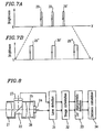
- Figure 5 is a schematic view of an optical system for an imaging apparatus of Example 3 according to the present invention.
- the optical system includes a lens 21 , a half mirror 22 , a first CCD 23 , a second CCD 24 , a housing 25 , and a magnifying lens 26 .
- the lens 21 , the half mirror 22 , the magnifying lens 26 , and the second CCD 24 are arranged coaxially, while the first CCD 23 is arranged along an axis of light reflected by the half mirror 22 .
- Part of light incident on the lens 21 is reflected by the half mirror 22 to be focused as a wide-angle mirror image on the first CCD 23 disposed along the axis of the reflected light.
- the remainder of the incident light which has passed through the half mirror 22 is magnified by the magnifying lens 26 and focused as a normal telescopic image on the second CCD 24 .
- Figure 6A illustrates a wide-angle image 27 obtained by re-inverting the mirror image obtained on the first CCD 23 using an electric signal.
- a fade-out point 28 in the wide-angle image 27 is an infinite point on a road.
- Left and right white lines 29 and 29' on the road intersect with each other at the fade-out point 28 as the infinite point.
- a broken line 30 on the road also intersects with the white lines 29 and 29' at the fade-out point 28 .
- Figure 6B illustrates a telescopic image 27' obtained on the second CCD 24 .
- a fade-out point 28' in the telescopic image 27' is an infinite point on the road.
- Left and right white lines 29'' and 29''' intersect with each other at the fade-out point 28' as the infinite point.
- a broken line 30' on the road also intersects with the white lines 29" and 29''' at the fade-out point 28' .
- the wide-angle image 27 and the telescopic image 27' are obtained from the coaxial optical system, the optical axes of these images can be aligned with each other. Also, considering the telescopic image 27' as a magnified image of a portion of the wide-angle image 27 by a simple operation, the two images can be superimposed.
- Figures 7A and 7B schematically show changes in brightness signals along a raster X-X in Figure 6A and a raster Y-Y in Figure 6B , respectively.
- the left white line 29 , the broken line 30 , and the right white line 29 ' on the road are positioned in the order from left to right in the normal image 27 obtained on the first CCD 23
- the signal X-X of Figure 7A represents the change in brightness in the above order.
- the rising of the brightness of the white line is used for the detection of the white line 29
- the left edge of the white line is detected.
- the left edges of the broken line 30 and the right white line 29' are detected in this order, thus continuously detecting the white lines along the raster. In this way, the geometry of the road using the left edges of the white lines is recognized.
- the left white line 29", the broken line 30' , and the right white lines 29'" on the road are positioned in the order from left to right in the telescopic image 27' obtained on the second CCD 24 , and the signal Y-Y of Figure 7B represents the change in brightness in the above order.
- the telescopic image 27' corresponds to a magnified view of a portion of the wide-angle image 27
- the width of the white lines 29", the broken line 30' , and the white line 29''' and the distances therebetween have been magnified. This allows the white lines on the road in the telescopic image to be observed in more detail.
- the road geometry can be recognized by continuously detecting the white lines along the raster.
- the road geometry using the left edges of the white lines in the wide-angle image and the road geometry using the left edges of the white lines in the telescopic image are recognized.
- These two road geometries basically match with each other.
- the white lines are blurred or defective, such a blurred or defective portion can be mutually complemented by the correlation with each other. In this way, the precision of the recognition of the white lines can be improved.
- Figure 8 is a block diagram of a distance measurement apparatus of Example 4 according to the present invention for measuring the distance between cars.
- the apparatus of this example includes an optical system for an imaging apparatus which is the same as the optical system for the imaging apparatus of Example 3 shown in Figure 5 .
- the distance measurement apparatus of this example includes the lens 21 , the half mirror 22 , the first CCD 23 , the second CCD 24 , the housing 25 , the magnifying mirror 26 , a lane detection section 31 , an image delimitation section 32 , a car characteristic detection section 33 , and a distance calculation section 34 .
- the lens 21 , the half mirror 22 , the magnifying lens 26 , and the second CCD 24 are arranged coaxially, while the first CCD 23 is arranged along an axis of light reflected by the half mirror 22 .
- the wide-angle image and the telescopic image output from the two CCDs 23 and 24 are supplied to respective portions for the wide-angle and telescopic images of the lane detection section 31 , the image delimitation section 32 , the car characteristic detection section 33 , and the distance calculation section 34 for processing.
- part of light incident on the lens 21 is reflected by the half mirror 22 to be focused as a wide-angle mirror image on the first CCD 23 disposed along the axis of the reflected light.
- the remainder of the incident light which has passed through the half mirror 22 is magnified by the magnifying lens 26 and focused as a normal telescopic image on the second CCD 24 .
- the wide-angle image 27 obtained by re-inverting the mirror image obtained on the first CCD 23 using an electric signal is input into the lane detection section 31 .
- the telescopic image 27' obtained on the second CCD 24 is also input into the lane detection section 31 .
- the lane detection section 31 detects vertical edges by scanning rightward and leftward along the scanning lines starting from the center of the bottom of each of the wide-angle image and the telescopic image to the top.
- the edges detected first are determined as outline points of the white lines on the road.
- the image delimitation section 32 converts the outline points on the image plane into coordinates on a plane coordinate system of the actual distance. More specifically, the outline points on the image plane coordinate system (hereinbelow, referred to as the "x-y plane coordinate system) are converted into points on a plane coordinate system where the Y-axis of an X-Y-Z stereo coordinate system corresponds to the road surface (hereinbelow, referred to as an "X-Z plane coordinate system) shown in Figure 10 .
- X, Y, and Z of this coordinate system are represented as follows.
- X (x/F) (Zcos ⁇ - Ysin ⁇ )
- Z Y (Fcos ⁇ + ysin ⁇ ) / (ycos ⁇ - Fsin ⁇ )
- Y -H
- F denotes the focal distance of the lens of the imaging apparatus
- ⁇ denotes the tilt angle of the optical axis
- H denotes the height of the imaging apparatus from the road surface.
- the car receives a change in pitch angle or a vertical vibration
- the outlines of the right and left white lines are no longer in parallel with each other.
- the outlines on the x-y plane coordinate system are shifted upward or downward to make the outlines of the right and left white lines parallel with each other.
- the above conversion is performed, so that the outlines of the right and left white lines on the X-Z plane coordinate system are in parallel with each other.
- the change in pitch angle or the vertical vibration is corrected.
- the image delimitation section delimits an area of the lane along which the car is travelling ahead of the car in the images received from the lane detection section 31 by using the lane along which the car is travelling detected by the lane detection section 31 ;
- the car characteristic detection section 33 detects horizontal edges in an area surrounded by right and left detection curves for each of the wide-angle image and the telescopic image. The number of edge points existing on each column of pixels in the direction vertical to the scanning line is then counted to produce a histogram.
- the histogram is searched from the bottom to the top, and the scanning line position where the number of edge points first exceeds a threshold value EB is determined as the position of a car travelling ahead. It is confirmed that the car has been detected at the same position in the wide-angle image and the telescopic image by overlapping the fade-out points in these images with each other.
- the distance calculation section 34 calculates the distance between the car and the car travelling ahead based on the scanning line position from the bottom of the image, and the height and the angle of depression of the imaging apparatus from the road surface. The smaller one of the values of the distance between the cars calculated from the wide-angle and telescopic image is determined as the distance between the cars.
- the distance measurement apparatus includes a lens 21 , a half mirror 22 , an infrared-sensitive CCD 23 , a visible-light-sensitive CCD 24 , a lane detection section 31 , an image delimitation section 32 , a car characteristic detection section 33 , and a distance calculation section 34 .
- Part of infrared light incident on the lens 21 is reflected by the half mirror 22 to be focused as an image on the infrared-sensitive CCD 23 .
- Part of visible light which has passed through the half mirror 22 is focused as an image on the visible-light-sensitive CCD 24 .
- An image obtained by re-inverting the image obtained on the CCD 23 using an electric signal is input into the lane detection section 31 .
- the image obtained on the CCD 24 is also input into the lane detection section 31 .
- the lane detection section 31 detects vertical edges by scanning rightward and leftward along the scanning lines starting from the center of the bottom of each of the infrared image and the visible-light image to the top. The edges detected first are determined as outline points of the white lines on the road.
- the image delimitation section 32 converts the outline points on the image plane into coordinates on a plane coordinate system of the actual distance. More specifically, the outline points on the image plane coordinate system (hereinbelow, referred to as the "x-y plane coordinate system) are converted into points on a plane coordinate system where the y-axis of an X-Y-Z stereo coordinate system corresponds to the road surface (hereinbelow, referred to as an "X-Z plane coordinate system). X, Y, and Z of this coordinate system are represented as follows.
- a car receives a change in pitch angle or a vertical vibration
- the outlines ( M1 and M2 ) of the right and left white lines are no longer parallel with each other.
- the outlines on the x-y plane coordinate system are shifted upward or downward to make the outlines ( M'1 and M'2 ) of the right and left white lines parallel with each other.
- the above conversion is performed, so that the outlines of the right and left white lines on the X-Z plane coordinate system are in parallel with each other.
- the change in pitch angle or the vertical vibration is corrected.
- the detected outline points are linked together from the bottom of the image.
- the car characteristic detection section 33 detects horizontal edges in an area surrounded by right and left detection curves for each of the infrared image and the visible-light image. The number of edge points existing on each column of pixels in the direction vertical to the scanning line is then counted to produce a histogram.
- the histogram is searched from the bottom to the top, and the scanning line position where the number of edge points first exceeds a threshold value EB is determined as the position of the car. It is confirmed that the car has been detected at the same position in the infrared image and the visible-light image by overlapping the fade-out points in these images with each other.
- the distance calculation section 34 calculates the distance between the car and a car travelling ahead based on the scanning line position from the bottom of the image, and the height and the angle of depression of the imaging apparatus from the road surface.
- a telescopic car tracing section is also provided for extracting a car characteristic closest to the bottom of the image among the car characteristics detected by a telescopic portion of the car characteristic detection section 33 and tracing the extracted car characteristic.
- a car determination section is provided for determining that a car detected by a wide-angle portion of the car characteristic detection section 33 is identical to the car traced by the telescopic car tracing section.
- a wide-angle distance calculation section is also provided for calculating a distance between the car and a car travelling ahead by using a car characteristic from the car determination section obtained when the car determined by the car determination section has just moved outside from the bottom of the image in the telescopic car tracing section.
- the imaging apparatus includes the optical system having the lens 1 , the half mirror 2 , and the second CCD 4 arranged coaxially, and the first CCD 3 arranged on the axis of light reflected from the half mirror.
- the image can be taken and processed in parallel at high speed, allowing for high-speed image recognition.
- the road geometry using the left edges of the white lines is obtained from the image which had passed through the color filter. Accordingly, the resultant road geometry is different in contrast from the road geometry using the right edges of the white lines obtained from the image without using a color filter.
- the white lines are blurred or defective, therefore, such a blurred or defective portion can be complemented by the correlation with each other. In this way, the precision of the recognition of the white lines can be improved.
- the road geometry using the left edges of the white lines in the wide-angle image and the road geometry using the left edges of the white lines in the telescopic image are recognized.
- These two road geometries basically match with each other.
- the white lines are blurred or defective, such a blurred or defective portion can be mutually complemented by the correlation with each other. In this way, the precision of the recognition of the white lines can be improved.
- the road geometry using the left edges of the white lines in the wide-angle image and the road geometry using the left edges of the white lines in the telescopic image are recognized.
- These two road geometries basically match with each other.
- the telescopic image which corresponds to a magnified image of a portion of the wide-angle image can be used to detect the white lines on the road in more detail.
- Such a blurred or defective portion can be complemented by the correlation with each other. In this way, the precision of the recognition of the white lines can be improved.
Landscapes
- Engineering & Computer Science (AREA)
- Physics & Mathematics (AREA)
- General Physics & Mathematics (AREA)
- Multimedia (AREA)
- Theoretical Computer Science (AREA)
- Electromagnetism (AREA)
- Radar, Positioning & Navigation (AREA)
- Remote Sensing (AREA)
- Traffic Control Systems (AREA)
- Image Processing (AREA)
- Measurement Of Optical Distance (AREA)
Claims (7)
- Bilderzeugungsvorrichtung, die umfasst:wobei entweder die erste oder die zweite CCD (4, 3) ein normales Bild eines über die Linse eingegebenen Eingangsbildes ausgibt, während die jeweils andere CCD ein umgekehrtes Bild des Eingangsbildes ausgibt,eine Linse (1), einen Halbspiegel (2) und eine erste CCD (4), die längs derselben optischen Achse angeordnet sind; undeine zweite CCD (3), die auf einer Achse von von dem Halbspiegel (2) reflektiertem Licht angeordnet ist,
und gekennzeichnet durch eine Bildverarbeitungsschaltung (31-34), um die Ausgangssignale der ersten und der zweiten CCD anhand ihrer umgekehrten Beziehung zu verarbeiten, um eine Bilderkennung auszuführen. - Bilderzeugungsvorrichtung nach Anspruch 1, die ferner ein wellenlängenselektives optisches Element (6) auf einem optischen Weg von der Linse (1) zu wenigstens einer der ersten und/oder der zweiten CCDs (4) umfasst.
- Bilderzeugungsvorrichtung nach Anspruch 2, bei der das wellenlängenselektive optische Element (6) ein Infrarotfilter ist.
- Bilderzeugungsvorrichtung nach Anspruch 2, bei der der Halbspiegel (2) auch als das wellenlängenselektive optische Element dient, das wahlweise Infrarotstrahlung reflektiert.
- Bilderzeugungsvorrichtung nach Anspruch 2, bei der der Halbspiegel (2) auch als das wellenlängenselektive optische Element dient, das Infrarotstrahlung wahlweise durchlässt.
- Bilderzeugungsvorrichtung nach Anspruch 1, die femer eine Vergrößerungslinse (6) in einem optischen Weg von der Linse zu wenigstens einer der ersten und zweiten CCDs umfasst.
- Bilderzeugungsvorrichtung nach Anspruch 1, bei der die Bildverarbeitungsschaltung ferner eine Schaltung zum Erfassen einer Korrelation zwischen dem normalen Bild und dem umgekehrten Bild umfasst.
Applications Claiming Priority (3)
| Application Number | Priority Date | Filing Date | Title |
|---|---|---|---|
| JP12925997 | 1997-05-20 | ||
| JP129259/97 | 1997-05-20 | ||
| JP12925997 | 1997-05-20 |
Publications (2)
| Publication Number | Publication Date |
|---|---|
| EP0880032A1 EP0880032A1 (de) | 1998-11-25 |
| EP0880032B1 true EP0880032B1 (de) | 2004-08-11 |
Family
ID=15005152
Family Applications (1)
| Application Number | Title | Priority Date | Filing Date |
|---|---|---|---|
| EP98109074A Expired - Lifetime EP0880032B1 (de) | 1997-05-20 | 1998-05-19 | Vorrichtung zur Erstellung eines Bildes sowie Verfahren und Vorrichtung zur Entfernungsmessung |
Country Status (3)
| Country | Link |
|---|---|
| US (1) | US6163022A (de) |
| EP (1) | EP0880032B1 (de) |
| DE (1) | DE69825525T2 (de) |
Families Citing this family (19)
| Publication number | Priority date | Publication date | Assignee | Title |
|---|---|---|---|---|
| WO2000048033A1 (en) | 1999-02-10 | 2000-08-17 | Matsushita Electric Industrial Co., Ltd. | Reflection optical device, reflection solid-state optical device, imaging device comprising this, multiwavelength imaging device, video camera, and monitoring device mounted on vehicle |
| JP3575346B2 (ja) * | 1999-09-03 | 2004-10-13 | 日本電気株式会社 | 道路白線検出システム、道路白線検出方法および道路白線検出用プログラムを記録した記録媒体 |
| TW594043B (en) | 2001-04-11 | 2004-06-21 | Matsushita Electric Industrial Co Ltd | Reflection type optical apparatus and photographing apparatus using the same, multi-wavelength photographing apparatus, monitoring apparatus for vehicle |
| WO2004042513A2 (en) * | 2002-10-30 | 2004-05-21 | Premier Wireless, Inc. | Queuing management and vessel recognition |
| US20050033505A1 (en) * | 2002-12-05 | 2005-02-10 | Premier Wireless, Inc. | Traffic surveillance and report system |
| RU2232401C1 (ru) * | 2003-04-07 | 2004-07-10 | Часовской Александр Абрамович | Устройство обработки сигналов |
| JP2005215985A (ja) * | 2004-01-29 | 2005-08-11 | Fujitsu Ltd | 走行車線判定プログラムおよびその記録媒体、走行車線判定装置ならびに走行車線判定方法 |
| JP4248558B2 (ja) * | 2006-03-24 | 2009-04-02 | トヨタ自動車株式会社 | 道路区画線検出装置 |
| DE102006060893A1 (de) * | 2006-05-12 | 2007-11-15 | Adc Automotive Distance Control Systems Gmbh | Vorrichtung und Verfahren zum Bestimmen eines Freiraums vor einem Fahrzeug |
| CN101449574B (zh) * | 2006-05-16 | 2012-01-25 | 松下电器产业株式会社 | 摄像装置和半导体电路元件 |
| TWI334517B (en) * | 2007-08-30 | 2010-12-11 | Ind Tech Res Inst | Method for predicting lane line and lane departure warning system using the same |
| JP5007840B2 (ja) * | 2009-05-22 | 2012-08-22 | トヨタ自動車株式会社 | 運転支援装置 |
| JP5830876B2 (ja) * | 2011-02-18 | 2015-12-09 | 富士通株式会社 | 距離算出プログラム、距離算出方法及び距離算出装置 |
| RU2524934C1 (ru) * | 2013-05-17 | 2014-08-10 | Сергей Владимирович Авраменко | Устройство определения дистанции при швартовке |
| JP6184877B2 (ja) | 2014-01-09 | 2017-08-23 | クラリオン株式会社 | 車両用外界認識装置 |
| CN106122859A (zh) * | 2014-06-23 | 2016-11-16 | 充梦霞 | 采用摄像控制模块的高亮led汽车灯及其工作方法 |
| CN104931957B (zh) * | 2015-06-01 | 2018-05-11 | 广东欧珀移动通信有限公司 | 一种基于移动终端的测距方法和装置 |
| CN105654432B (zh) * | 2015-12-23 | 2017-05-17 | 华中科技大学 | 一种气动热辐射效应的频域校正方法 |
| AT518940B1 (de) * | 2016-08-03 | 2019-11-15 | Zkw Group Gmbh | Verfahren und Vorrichtung zum Messen eines Abstands zwischen einem ersten Fahrzeug und einem zweiten, dem ersten Fahrzeug unmittelbar vorausfahrenden, Fahrzeug |
Family Cites Families (15)
| Publication number | Priority date | Publication date | Assignee | Title |
|---|---|---|---|---|
| US3562537A (en) * | 1969-09-03 | 1971-02-09 | Us Army | Electro-optical decorrelation of wavefront distortion due to atmospheric scintillation |
| JP2849813B2 (ja) * | 1986-12-19 | 1999-01-27 | 富士写真フイルム株式会社 | 映像信号の形成装置 |
| JP2535927B2 (ja) * | 1987-07-09 | 1996-09-18 | アイシン精機株式会社 | 車上距離検出装置 |
| DE3905591C2 (de) * | 1989-02-23 | 1997-08-28 | Rheinmetall Ind Ag | Vorrichtung zur Gewinnung kontrastreicher Bilder |
| DE3927334C1 (de) * | 1989-08-18 | 1991-01-10 | Messerschmitt-Boelkow-Blohm Gmbh, 8012 Ottobrunn, De | |
| DE4111993B4 (de) * | 1990-04-23 | 2005-05-25 | Volkswagen Ag | Kamera für ein Bildverarbeitungssystem |
| US5309137A (en) * | 1991-02-26 | 1994-05-03 | Mitsubishi Denki Kabushiki Kaisha | Motor car traveling control device |
| IT1256956B (it) * | 1992-10-05 | 1995-12-27 | Gilardini Spa | Dispositivo per rilevare posizioni relative tra veicoli, principalmente in funzione anticollisione. |
| JP3004158B2 (ja) * | 1993-11-08 | 2000-01-31 | 松下電器産業株式会社 | 車両認識装置 |
| JP3209828B2 (ja) * | 1993-05-25 | 2001-09-17 | 松下電器産業株式会社 | 車間距離計測装置とステレオ画像取り込み装置 |
| JP2862199B2 (ja) * | 1993-05-25 | 1999-02-24 | 松下電器産業株式会社 | 車両認識装置 |
| JP3169483B2 (ja) * | 1993-06-25 | 2001-05-28 | 富士通株式会社 | 道路環境認識装置 |
| JP3205477B2 (ja) * | 1994-02-17 | 2001-09-04 | 富士フイルムマイクロデバイス株式会社 | 車間距離検出装置 |
| JPH07334800A (ja) * | 1994-06-06 | 1995-12-22 | Matsushita Electric Ind Co Ltd | 車両認識装置 |
| JPH0875454A (ja) * | 1994-09-01 | 1996-03-22 | Nissan Motor Co Ltd | 測距装置 |
-
1998
- 1998-05-18 US US09/080,854 patent/US6163022A/en not_active Expired - Fee Related
- 1998-05-19 DE DE69825525T patent/DE69825525T2/de not_active Expired - Fee Related
- 1998-05-19 EP EP98109074A patent/EP0880032B1/de not_active Expired - Lifetime
Also Published As
| Publication number | Publication date |
|---|---|
| DE69825525D1 (de) | 2004-09-16 |
| US6163022A (en) | 2000-12-19 |
| EP0880032A1 (de) | 1998-11-25 |
| DE69825525T2 (de) | 2005-09-01 |
Similar Documents
| Publication | Publication Date | Title |
|---|---|---|
| EP0880032B1 (de) | Vorrichtung zur Erstellung eines Bildes sowie Verfahren und Vorrichtung zur Entfernungsmessung | |
| US11505123B2 (en) | Vehicular camera monitoring system with stereographic display | |
| JP3105934B2 (ja) | 乗物の前方の通路を捕捉する画像処理系用のカメラ | |
| US7385680B2 (en) | Camera module | |
| JP4425495B2 (ja) | 車外監視装置 | |
| JP3168177U (ja) | マイクロレンズマトリックスに連結された光検出器マトリックスを備える多機能光学センサ | |
| US7652686B2 (en) | Device for image detecting objects, people or similar in the area surrounding a vehicle | |
| US20050196034A1 (en) | Obstacle detection system and method therefor | |
| EP1087257B1 (de) | Stereoskopisches Kamerasystem in einem Fahrzeug | |
| EP3667413B1 (de) | Stereobildverarbeitungsvorrichtung | |
| JPH1139596A (ja) | 車外監視装置 | |
| JPH0719861A (ja) | 走査式光学距離計 | |
| WO2020213386A1 (ja) | 物体位置検出装置、走行制御システム、および走行制御方法 | |
| JPH08136237A (ja) | 走行路勾配算出装置および車速制御装置 | |
| JP3991501B2 (ja) | 3次元入力装置 | |
| JP3540005B2 (ja) | 障害物検出装置 | |
| EP0882211B1 (de) | Verfahren und apparat zur reduzierung von unerwünschten rauscheffekten in einem dreidimensionalen farbbilderzeugungssystem | |
| JPH1141521A (ja) | 撮像装置および車間距離計測装置ならびに車間距離計測方法 | |
| JP2006031101A (ja) | 画像生成方法およびその装置 | |
| JP2008157851A (ja) | カメラモジュール | |
| JPS62194413A (ja) | 三次元座標計測装置 | |
| JPS6383604A (ja) | 三次元座標計測装置 | |
| JPH08108796A (ja) | 車両用周辺視認装置 | |
| JP2005117136A (ja) | 車両用物体検出装置 | |
| US20260116299A1 (en) | Vehicular camera with reduced packaging depth |
Legal Events
| Date | Code | Title | Description |
|---|---|---|---|
| PUAI | Public reference made under article 153(3) epc to a published international application that has entered the european phase |
Free format text: ORIGINAL CODE: 0009012 |
|
| 17P | Request for examination filed |
Effective date: 19980526 |
|
| AK | Designated contracting states |
Kind code of ref document: A1 Designated state(s): DE FR GB |
|
| AX | Request for extension of the european patent |
Free format text: AL;LT;LV;MK;RO;SI |
|
| AKX | Designation fees paid |
Free format text: DE FR GB |
|
| 17Q | First examination report despatched |
Effective date: 20011017 |
|
| GRAP | Despatch of communication of intention to grant a patent |
Free format text: ORIGINAL CODE: EPIDOSNIGR1 |
|
| GRAA | (expected) grant |
Free format text: ORIGINAL CODE: 0009210 |
|
| GRAS | Grant fee paid |
Free format text: ORIGINAL CODE: EPIDOSNIGR3 |
|
| AK | Designated contracting states |
Kind code of ref document: B1 Designated state(s): DE FR GB |
|
| REG | Reference to a national code |
Ref country code: GB Ref legal event code: FG4D |
|
| REF | Corresponds to: |
Ref document number: 69825525 Country of ref document: DE Date of ref document: 20040916 Kind code of ref document: P |
|
| ET | Fr: translation filed | ||
| PLBE | No opposition filed within time limit |
Free format text: ORIGINAL CODE: 0009261 |
|
| STAA | Information on the status of an ep patent application or granted ep patent |
Free format text: STATUS: NO OPPOSITION FILED WITHIN TIME LIMIT |
|
| 26N | No opposition filed |
Effective date: 20050512 |
|
| PGFP | Annual fee paid to national office [announced via postgrant information from national office to epo] |
Ref country code: DE Payment date: 20070517 Year of fee payment: 10 |
|
| PGFP | Annual fee paid to national office [announced via postgrant information from national office to epo] |
Ref country code: GB Payment date: 20070516 Year of fee payment: 10 |
|
| PGFP | Annual fee paid to national office [announced via postgrant information from national office to epo] |
Ref country code: FR Payment date: 20070510 Year of fee payment: 10 |
|
| GBPC | Gb: european patent ceased through non-payment of renewal fee |
Effective date: 20080519 |
|
| REG | Reference to a national code |
Ref country code: FR Ref legal event code: ST Effective date: 20090119 |
|
| PG25 | Lapsed in a contracting state [announced via postgrant information from national office to epo] |
Ref country code: FR Free format text: LAPSE BECAUSE OF NON-PAYMENT OF DUE FEES Effective date: 20080602 Ref country code: DE Free format text: LAPSE BECAUSE OF NON-PAYMENT OF DUE FEES Effective date: 20081202 |
|
| PG25 | Lapsed in a contracting state [announced via postgrant information from national office to epo] |
Ref country code: GB Free format text: LAPSE BECAUSE OF NON-PAYMENT OF DUE FEES Effective date: 20080519 |