EP0880108A1 - Procédé de traitement d'une image incluant une étape de chainage, et appareil d'imagerie médicale incluant des moyens pour mettre en oeuvre ce procédé - Google Patents
Procédé de traitement d'une image incluant une étape de chainage, et appareil d'imagerie médicale incluant des moyens pour mettre en oeuvre ce procédé Download PDFInfo
- Publication number
- EP0880108A1 EP0880108A1 EP98201523A EP98201523A EP0880108A1 EP 0880108 A1 EP0880108 A1 EP 0880108A1 EP 98201523 A EP98201523 A EP 98201523A EP 98201523 A EP98201523 A EP 98201523A EP 0880108 A1 EP0880108 A1 EP 0880108A1
- Authority
- EP
- European Patent Office
- Prior art keywords
- image
- intensity
- points
- point
- state
- Prior art date
- Legal status (The legal status is an assumption and is not a legal conclusion. Google has not performed a legal analysis and makes no representation as to the accuracy of the status listed.)
- Withdrawn
Links
Images


Classifications
-
- G—PHYSICS
- G06—COMPUTING OR CALCULATING; COUNTING
- G06T—IMAGE DATA PROCESSING OR GENERATION, IN GENERAL
- G06T7/00—Image analysis
- G06T7/10—Segmentation; Edge detection
- G06T7/155—Segmentation; Edge detection involving morphological operators
-
- G—PHYSICS
- G06—COMPUTING OR CALCULATING; COUNTING
- G06T—IMAGE DATA PROCESSING OR GENERATION, IN GENERAL
- G06T7/00—Image analysis
- G06T7/10—Segmentation; Edge detection
- G06T7/12—Edge-based segmentation
-
- G—PHYSICS
- G06—COMPUTING OR CALCULATING; COUNTING
- G06T—IMAGE DATA PROCESSING OR GENERATION, IN GENERAL
- G06T2207/00—Indexing scheme for image analysis or image enhancement
- G06T2207/10—Image acquisition modality
- G06T2207/10116—X-ray image
-
- G—PHYSICS
- G06—COMPUTING OR CALCULATING; COUNTING
- G06T—IMAGE DATA PROCESSING OR GENERATION, IN GENERAL
- G06T2207/00—Indexing scheme for image analysis or image enhancement
- G06T2207/30—Subject of image; Context of image processing
- G06T2207/30004—Biomedical image processing
- G06T2207/30101—Blood vessel; Artery; Vein; Vascular
Definitions
- the invention relates to an image processing method. including the acquisition of an intensity image formed by a matrix of points with non-binary intensity values, representing filiform objects, and including steps for detecting filiform objects.
- the invention finds application in the industry of manufacture of x-ray radiology equipment for example.
- This publication describes an algorithm for detecting contour line of isolated objects in noisy images which is a variant of a method well known to those skilled in the art under the dynamic programming name.
- the programming method dynamic applies under two conditions: it is a method of finding the shortest way to connect a group of points with minimal cost. This method needs to be guided; she therefore cannot be automated.
- the object of the present invention is to propose a method image processing, as defined above, applying under more conditions than the programming method known dynamics: the calculation steps must take place from automatic way; the number of stages must be as low as possible ; these steps should determine the shortest path to connect a group of points belonging to a threadlike object individual, with the lowest possible cost; and the way chosen must include as many points as possible the filiform object, so be the longest and most regular possible in the picture.
- the condition that the path found must include the highest possible density of points belonging to the threadlike object is unknown to the programming method dynamic.
- This process has the advantage of being applied to processing of low-contrast medical X-ray images originally, such as arteriograms.
- this process allows for example segmentation automatic arteries of different diameters from the bottom which includes an annoying representation of the ribs.
- this process allows for example a automatic segmentation of highly tangled arteries.
- this method offers the advantage of allowing the detection and improved reconstruction of edges or lines in many types of objects represented in images, without original condition of these images.
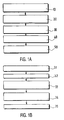
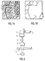
- FIGS.1A and 1B The process described below is illustrated by FIGS.1A and 1B in the form of functional block diagrams, and concerns in general the processing of an image of intensity not binary, called the original image J, as shown example in FIG.7A, representing threadlike objects.
- the filiform objects can be, for example, edges of objects, edges, center lines of objects.
- This process includes processing steps applied to this original image J and including at least one step of chaining 30 pixels belonging to a threadlike object.
- the method further comprises favorably a step of tracking 40 of each filiform object individually in image K as illustrated in FIG.7B.
- the local characteristics oriented in intensity are favorably the modulus intensity gradient ⁇ G ⁇ at A, and the orientation ⁇ of the gradient vector G calculated with respect to one of the coordinate axes OX .
- These calculations can be carried out favorably by way of example, by systematic conventional scanning of the original image, by means of filters for deriving the intensity values called Sovel filters which determine the slope denoted Gx of the intensity values from of a given pixel A in the direction OX , and the slope Gy of the intensity values from the same pixel A in the direction OY .
- STATES relating to the pixels of the original image J, which form a "field of characteristics intensity-oriented local ", or STATE field, or intensity vectors forming an image of STATES.
- the gradient is calculated in a volume at instead of being calculated on a plane, and the rest of the processing is adapted to this data in any automatic manner known to man of career.
- the invention is not limited to the detection of lines of edge. Any line can be detected automatically provided that each location of pixels in the image is associated with a intensity vector, defined by its module and its angle that is descriptive of the line in its environment.
- G E1 associated with an angle ⁇ E1 and the gradient vector G E2 associated with an angle ⁇ E2 .
- a point on the midline of the vessels is then A (x, y) located at the point of intersection of the directions of the gradient vectors G E1 , G E2 .
- step 20 for the potential midpoints, a STATE image formed of a "field of intensity-oriented local characteristics" or field of STATES or field of intensity vectors is defined,
- a STATE is defined at least by an x, y location and an intensity vector V two components of which are the intensity module ⁇ V ⁇ of the vector and an orientation angle ⁇ of V relative to a benchmark OX , preferably discretized.
- a step 30 of chaining the pixels belonging to an object threadlike from the original image is an operation which consists in determining from a given pixel, from near near, a path formed by pixels of a threadlike object which is the as long and as regular as possible in the original image.
- a pixel predecessor or antecedent
- Filtering according to criterion Q (i) detects STATES continuous, that is to say a continuous vector field. for example in the case of edge detection, this filtering detects the continuous gradient fields. This filtering determines the STATE most likely predecessor k (i) to be linked to STATE i, of automatically and at a lower cost.
- the image of the STATES is automatically scanned in at least one direction.
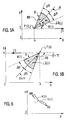
- a conventional scan can be carried out along the lines in the direction Z1 parallel to the axis OX , from top left to bottom right, in the CAUSAL direction, in the STATES image.
- This scanning makes it possible to determine the predecessor STATE k (i) in the region of the image already scanned, which is located higher or more to the left than the current STATUS i scanned.
- the STATES image is then automatically scanned along the lines in the direction Z2 ANTICAUSALE, from bottom right to top left of the STATES image, parallel to OX .
- This second scan makes it possible to determine a STATE h (i) successor to the current STATUS i scanned.
- systematic causal and anticausal scans are still carried out in directions Z3 and Z4 perpendicular to the directions Z1 and Z2 of the first scans.
- the first systematic scans are made along the lines parallel to the axis OX
- the second systematic scans are carried out according to columns parallel to the axis OY , CAUSALLY AND ANTICAUSALLY.
- a neighborhood is determined in the image region of states already scanned which is constituted by an angular search sector denoted NB centered on the state i scanned and which makes an angle ⁇ ⁇ around the direction ⁇ of the vector V . Thanks to this neighborhood NB, it is possible to search for the best neighboring STATE in a continuous vector field.
- a STATE j is sought which maximizes criterion 2), that is to say whose angle ⁇ is close to that of the given STATE i, and for which the disparity measure a ij in cooperation with the value of the modulus of the gradient ⁇ G j ⁇ F at j and the value of the modulus of the gradient ⁇ G i ⁇ in i allow to obtain ⁇ G i ⁇ F maximum by applying criterion 2).
- the neighborhood is also limited by a maximum distance R of the neighboring STATE examined j with respect to the current STATE i scanned. It can, for example, in this case, be 10 to 100 neighboring states possible in the angular sector NB determined. To this end, for each current STATE i scanned, 10 to 100 corresponding tests are carried out, in the region already scanned and on the STATES j contained in the determined neighborhood NB by applying criterion 2). Among all the STATES j tested in the search neighborhood NB, we retain the one that maximizes the criterion Q (i), and we denote it k (i).
- substeps 33 to 35 After substeps 33 to 35 starting with a CAUSAL scan 33, repeating of sub-steps 33 to 35 starting with an ANTICAUSAL scan, which allows determine by the same method a successor STATE which is stored and noted h (i). Then, repetitions of sub-steps 33 to 35 with perpendicular causal and anticausal scans, and we seeks if there is a STATE j, always in the neighborhood NB predetermined, which would provide an improved Q (i) value. In that case, it is this new state value j which is stored for k (i) or h (i), and the value found in substeps 33 to 35 with previous scans is forgotten.
- the invention is not limited to pairing STATES determined at the same resolution.
- We can favorably filter the original image at various resolutions, called ⁇ scales, to form a set of multiscale images, and in this case, best neighboring STATES are sought at different scales, the nearest scales are nevertheless preferred, for example by applying to the value Q (j) in equation 2), a appropriate weight.
- the path determined by the proposed chaining method has specific properties; that's why we gave filtering which gives this path the name of FILTERING GEODESICS by analogy to a geographic notation.
- the determination of this path makes it possible to fill small cuts in the threadlike object in the image of the fact that the best neighbor STATE found in the determined neighborhood is not necessarily the STATE which is at the shortest distance but the STATE which is at a short distance depending on oriented local characteristics intensity of low disparity.
- the process does not allow not to fill large cuts which allows to separate two different threadlike objects.
- This GEODESIC filtering is "constrained" by the conditions of location, angle, and intensity and occasionally of scale which are linked to the sweep, to the sector of research, and to criterion 2) proposed, and enhances the objects elongated or threadlike.
- An automatic back-tracking step 40 In this step, we chain the STATES corresponding to the different filiform objects in the image.
- tracking automatic includes a first determination of a point i of the image for which the largest value Q (i) was found.
- the automatic tracking includes a second determination of another point of the image for which we found a value Q (i) also as large as possible, from which we create a new chain upstream and a new downstream chain.
- Automatic tracking is facts as long as there are starting points of chain having sufficiently large Q (i) values: a threshold can be set. Paths already visited are not revisited. To this end, the new possible starting points of chain are only retained if they are at a sufficient predetermined distance from the chains already existing. Thus, intersecting threadlike objects are detected individually in the image. There can be no ambiguity in the segmentation of objects.
- FIG. 4B shows in an image K the result of the chain of the filiform objects of image J of FIG.4A.
- an apparatus of digital radiography includes a source 1 of X-rays ; a movable table 2 for receiving a patient; a image intensifier device 3 coupled to a video tube 4, which provides data to a digital image processing system 8 comprising a microprocessor 5.
- the latter comprises several outputs including an output 6 coupled to a monitor 7 for the viewing the radiographic image or intensity images.
- the scanned radiographic image may contain 512 x 512 or 1024 x 1024 pixels coded on 8 bits or 10 bits. Each pixel can be assigned one of 256 or 1024 levels intensity. For example, dark regions have a level of low intensity, and the bright regions of the image have a level high intensity.
- the scanned image can be obtained in fluoroscopic. The invention can find its application particularly in the processing of arteriographic images.
- Digital image processing according to the process described above is implemented in its various stages and operations in the system 5.
- the data is stored in a memory area not shown and displayed if necessary on a monitor 7.
- Means of recording also noted 7 may be in additionally used.
- the digitization of the image to be treated brings a advantage in the implementation of the present method.
Landscapes
- Engineering & Computer Science (AREA)
- Computer Vision & Pattern Recognition (AREA)
- Physics & Mathematics (AREA)
- General Physics & Mathematics (AREA)
- Theoretical Computer Science (AREA)
- Image Analysis (AREA)
- Image Processing (AREA)
- Apparatus For Radiation Diagnosis (AREA)
Abstract
Description
le module du gradient d'intensité
l'angle ϕ que fait le vecteur gradient
Claims (8)
- Procédé de traitement d'image incluant l'acquisition (10) d'une image d'intensité (J) formée d'une matrice de points (A) munie de valeurs d'intensité non binaires, représentant des objets filiformes, et incluant des étapes de détection des objets filiformes comprenant :une détermination automatique (20) d'un champ de vecteurs d'intensité (
V ) formant une image d'ETATS constitués par des caractéristiques de grandeurs et d'angles [∥V ∥,] des vecteurs d'intensité aux différents points (A) de l'image d'intensité,une opération de chaínage (30) des points d'un objet filiforme individuel au moyen d'un filtrage automatique [Q(i)] de l'image des ETATS qui effectue une sélection d'un champ dense et continu de vecteurs d'intensité correspondant à des points de l'objet filiforme. - Procédé selon la revendication 1 selon lequel l'opération de chaínage (30) par filtrage automatique de l'image des ETATS comprend :la définition d'un critère [Q(i)] de filtrage qui fournit la valeur filtrée de la grandeur [∥
V i∥F] du vecteur d'intensité en un point d'ETAT(i) donné de l'image des ETATS comme une somme de la grandeur [P(i),∥V i∥] non filtrée du vecteur d'intensité en ce point et de la grandeur [Q(j),∥V j∥F] filtrée du vecteur d'intensité en un point d'ETAT (j) voisin pondérée par un coefficient de probabilité (αi,j) d'appariement des points d'ETAT (i,j) en dépendance d'une mesure de leur disparité (aij),la recherche d'un point [k(i) ; h(i)] parmi des points d'ETAT (j) voisins dont les caractéristiques de grandeur et d'angle des vecteurs d'intensité maximise le critère [Q(i)] de filtrage au point d'ETAT donné (i). - Procédé selon la revendication 2, selon lequel l'opération de chaínage comprend : un balayage (33) systématique et automatique de l'image des ETATS selon au moins une direction (
Z1 ) ; en un point d'ETAT (i) courant, une recherche (34) dans la zone de l'image déjà balayée, d'un point d'ETAT prédécesseur [k(i)] et/ou successeur [h(i)] pour lequel le critère [Q(i)] est maximal ; et le stockage desdits points d'ETAT prédécesseur [k(i)] et/ou successeur [h(i)] comme points à chaíner avec ledit point courant (i). - Procédé selon la revendication 3, selon lequel, l'opération de recherche (34) d'un ETAT prédécesseur [k(i)] et/ou successeur [h(i)] d'un ETAT donné (i) dans l'image des ETATS comprend la détermination d'un voisinage de recherche (NB) formé d'un secteur angulaire centré sur ledit point d'ETAT donné (i), et qui couvre un angle donné (± ΔΘ) autour de l'angle d'orientation (Θ) du vecteur d'intensité (
V i) relatif au point d'ETAT donné (i), et la détermination dans ce voisinage de recherche, d'un point d'ETAT [k(i) ; h(i)] parmi les points d'ETATS(j) du secteur de recherche pour lequel le critère est maximal. - Procédé selon la revendication 4, selon lequel le voisinage de recherche (NB) est limité en outre à une zone de rayon prédéterminé (R) autour du point courant (i).
- Procédé selon l'une des revendications 1 à 5, qui comprend en outre une opération de pistage (40) des points d'ETATS de différents objets filiformes individuellement.
- Procédé selon la revendication 6, selon lequel, l'opération de pistage comprend la détermination d'un point d'ETAT (i) d'intérêt, par l'examen de la valeur [Q(i)] obtenue par la mise en oeuvre du critère de filtrage, comme point de départ d'une opération de chaínage ; le chaínage de son prédécesseur [k(i)] et de son successeur [h(i)] et de proche en proche de tous les prédécesseurs des prédécesseurs et successeurs des successeurs s'il s'en trouve, de part et d'autre (AM,AV) du point de départ, de manière à former une chaíne de points représentatifs de l'objet filiforme ; le renouvellement de ces opérations pour pister les différents objets filiformes de l'image avec la condition que les point de départ sont choisis non confondus avec des points d'une chaíne déjà existante.
- Appareil d'imagerie médicale incluant des moyens pour mettre en oeuvre un procédé selon l'une des revendications 1 à 7, comprenant un système d'acquisition (4) de données de représentation d'une image sous forme d'une matrice bidimensionnelle de points ayant des valeurs d'intensités non binaires, repérés par leurs coordonnées dans la matrice,un système de traitement d'image (8) comprenant un microprocesseur (5) ayant accès aux données de représentation de l'image et munis de moyens pour mettre en oeuvre les étapes du procédé,et un système d'affichage et/ou d'enregistrement (7) des données d'image acquises et/ou traitées par le procédé.
Applications Claiming Priority (2)
| Application Number | Priority Date | Filing Date | Title |
|---|---|---|---|
| FR9706339 | 1997-05-23 | ||
| FR9706339 | 1997-05-23 |
Publications (1)
| Publication Number | Publication Date |
|---|---|
| EP0880108A1 true EP0880108A1 (fr) | 1998-11-25 |
Family
ID=9507186
Family Applications (1)
| Application Number | Title | Priority Date | Filing Date |
|---|---|---|---|
| EP98201523A Withdrawn EP0880108A1 (fr) | 1997-05-23 | 1998-05-11 | Procédé de traitement d'une image incluant une étape de chainage, et appareil d'imagerie médicale incluant des moyens pour mettre en oeuvre ce procédé |
Country Status (3)
| Country | Link |
|---|---|
| US (1) | US6430315B1 (fr) |
| EP (1) | EP0880108A1 (fr) |
| JP (1) | JPH114383A (fr) |
Cited By (2)
| Publication number | Priority date | Publication date | Assignee | Title |
|---|---|---|---|---|
| FR2818855A1 (fr) * | 2000-12-26 | 2002-06-28 | Koninkl Philips Electronics Nv | Procede de traitement d'images |
| US6859104B2 (en) | 2001-04-11 | 2005-02-22 | Kyocera Wireless Corp. | Tunable power amplifier matching circuit |
Families Citing this family (47)
| Publication number | Priority date | Publication date | Assignee | Title |
|---|---|---|---|---|
| JP4571753B2 (ja) * | 2001-03-05 | 2010-10-27 | 株式会社ニレコ | 画像処理における繊維状粒子の分離方法 |
| SE0201894D0 (sv) * | 2002-06-19 | 2002-06-19 | Ludesi Ab | Method for digital image processing |
| DE102004008979B4 (de) * | 2004-02-24 | 2006-12-28 | Siemens Ag | Verfahren zur Filterung tomographischer 3D-Darstellungen nach erfolgter Rekonstruktion von Volumendaten |
| US7190819B2 (en) * | 2004-10-29 | 2007-03-13 | Stereotaxis, Inc. | Image-based medical device localization |
| US7684602B2 (en) * | 2004-11-18 | 2010-03-23 | Siemens Medical Solutions Usa, Inc. | Method and system for local visualization for tubular structures |
| US8784336B2 (en) | 2005-08-24 | 2014-07-22 | C. R. Bard, Inc. | Stylet apparatuses and methods of manufacture |
| US7794407B2 (en) | 2006-10-23 | 2010-09-14 | Bard Access Systems, Inc. | Method of locating the tip of a central venous catheter |
| US8388546B2 (en) | 2006-10-23 | 2013-03-05 | Bard Access Systems, Inc. | Method of locating the tip of a central venous catheter |
| US9521961B2 (en) | 2007-11-26 | 2016-12-20 | C. R. Bard, Inc. | Systems and methods for guiding a medical instrument |
| CN103750858B (zh) | 2007-11-26 | 2017-04-12 | C·R·巴德股份有限公司 | 用于脉管系统内的导管放置的集成系统 |
| US10449330B2 (en) | 2007-11-26 | 2019-10-22 | C. R. Bard, Inc. | Magnetic element-equipped needle assemblies |
| US10524691B2 (en) | 2007-11-26 | 2020-01-07 | C. R. Bard, Inc. | Needle assembly including an aligned magnetic element |
| US10751509B2 (en) | 2007-11-26 | 2020-08-25 | C. R. Bard, Inc. | Iconic representations for guidance of an indwelling medical device |
| US9456766B2 (en) | 2007-11-26 | 2016-10-04 | C. R. Bard, Inc. | Apparatus for use with needle insertion guidance system |
| US8849382B2 (en) | 2007-11-26 | 2014-09-30 | C. R. Bard, Inc. | Apparatus and display methods relating to intravascular placement of a catheter |
| US9649048B2 (en) | 2007-11-26 | 2017-05-16 | C. R. Bard, Inc. | Systems and methods for breaching a sterile field for intravascular placement of a catheter |
| US8781555B2 (en) | 2007-11-26 | 2014-07-15 | C. R. Bard, Inc. | System for placement of a catheter including a signal-generating stylet |
| US8478382B2 (en) | 2008-02-11 | 2013-07-02 | C. R. Bard, Inc. | Systems and methods for positioning a catheter |
| US8437570B2 (en) * | 2008-05-23 | 2013-05-07 | Microsoft Corporation | Geodesic image and video processing |
| US9901714B2 (en) | 2008-08-22 | 2018-02-27 | C. R. Bard, Inc. | Catheter assembly including ECG sensor and magnetic assemblies |
| US8437833B2 (en) | 2008-10-07 | 2013-05-07 | Bard Access Systems, Inc. | Percutaneous magnetic gastrostomy |
| US8351654B2 (en) * | 2009-04-28 | 2013-01-08 | Microsoft Corporation | Image processing using geodesic forests |
| US9532724B2 (en) | 2009-06-12 | 2017-01-03 | Bard Access Systems, Inc. | Apparatus and method for catheter navigation using endovascular energy mapping |
| US9445734B2 (en) | 2009-06-12 | 2016-09-20 | Bard Access Systems, Inc. | Devices and methods for endovascular electrography |
| CN102802514B (zh) | 2009-06-12 | 2015-12-02 | 巴德阿克塞斯系统股份有限公司 | 导管末端定位设备 |
| EP2482719A4 (fr) | 2009-09-29 | 2016-03-09 | Bard Inc C R | Stylets pour utilisation avec appareil pour placement intravasculaire d'un cathéter |
| US11103213B2 (en) | 2009-10-08 | 2021-08-31 | C. R. Bard, Inc. | Spacers for use with an ultrasound probe |
| CN102113900B (zh) * | 2010-01-05 | 2015-07-15 | 深圳迈瑞生物医疗电子股份有限公司 | 彩色血流动态帧相关方法和装置 |
| CN102821679B (zh) | 2010-02-02 | 2016-04-27 | C·R·巴德股份有限公司 | 用于导管导航和末端定位的装置和方法 |
| ES2778041T3 (es) | 2010-05-28 | 2020-08-07 | Bard Inc C R | Aparato para su uso con sistema de guiado de inserción de aguja |
| CA2806353A1 (fr) | 2010-08-09 | 2012-02-16 | C.R. Bard Inc. | Structures de support et de capuchon pour tete de sonde a ultrasons |
| US20120046562A1 (en) | 2010-08-20 | 2012-02-23 | C. R. Bard, Inc. | Reconfirmation of ecg-assisted catheter tip placement |
| EP2632360A4 (fr) | 2010-10-29 | 2014-05-21 | Bard Inc C R | Mise en place assistée par bio-impédance d'un dispositif médical |
| CA2835890A1 (fr) | 2011-07-06 | 2013-01-10 | C.R. Bard, Inc. | Determination et etalonnage de longueur d'aiguille pour un systeme de guidage d'introduction |
| USD724745S1 (en) | 2011-08-09 | 2015-03-17 | C. R. Bard, Inc. | Cap for an ultrasound probe |
| USD699359S1 (en) | 2011-08-09 | 2014-02-11 | C. R. Bard, Inc. | Ultrasound probe head |
| WO2013070775A1 (fr) | 2011-11-07 | 2013-05-16 | C.R. Bard, Inc | Insert à base d'hydrogel renforcé pour ultrasons |
| US8781173B2 (en) | 2012-02-28 | 2014-07-15 | Microsoft Corporation | Computing high dynamic range photographs |
| EP2861153A4 (fr) | 2012-06-15 | 2016-10-19 | Bard Inc C R | Appareil et procédés permettant la détection d'un capuchon amovible sur une sonde à ultrasons |
| WO2015120256A2 (fr) | 2014-02-06 | 2015-08-13 | C.R. Bard, Inc. | Systèmes et procédés pour le guidage et le placement d'un dispositif intravasculaire |
| US10973584B2 (en) | 2015-01-19 | 2021-04-13 | Bard Access Systems, Inc. | Device and method for vascular access |
| US10349890B2 (en) | 2015-06-26 | 2019-07-16 | C. R. Bard, Inc. | Connector interface for ECG-based catheter positioning system |
| US11000207B2 (en) | 2016-01-29 | 2021-05-11 | C. R. Bard, Inc. | Multiple coil system for tracking a medical device |
| CN108846839B (zh) * | 2018-06-05 | 2021-08-10 | 中南大学 | 一种基于扇形邻域差异直方图的匣钵裂纹检测方法 |
| CN112867443B (zh) | 2018-10-16 | 2024-04-26 | 巴德阿克塞斯系统股份有限公司 | 用于建立电连接的安全装备连接系统及其方法 |
| US12544101B2 (en) | 2019-01-30 | 2026-02-10 | Bard Access Systems, Inc. | Systems and methods for tracking medical devices |
| JP2024028043A (ja) * | 2022-08-19 | 2024-03-01 | 富士フイルム株式会社 | 情報処理装置、情報処理方法、及びプログラム |
Citations (1)
| Publication number | Priority date | Publication date | Assignee | Title |
|---|---|---|---|---|
| DE4304860A1 (de) * | 1993-02-17 | 1994-08-18 | Siemens Ag | Verfahren zur Verbesserung der Sichtbarkeit von linienhaften Strukturen in einem digitalen Bild |
Family Cites Families (13)
| Publication number | Priority date | Publication date | Assignee | Title |
|---|---|---|---|---|
| GB1171627A (en) * | 1966-10-07 | 1969-11-26 | Post Office | Improvements in or relating to Character Recognition Machines |
| US4183013A (en) * | 1976-11-29 | 1980-01-08 | Coulter Electronics, Inc. | System for extracting shape features from an image |
| US4490848A (en) * | 1982-03-31 | 1984-12-25 | General Electric Company | Method and apparatus for sorting corner points in a visual image processing system |
| GB8311813D0 (en) * | 1983-04-29 | 1983-06-02 | West G A W | Coding and storing raster scan images |
| US4791581A (en) * | 1985-07-27 | 1988-12-13 | Sony Corporation | Method and apparatus of forming curved surfaces |
| JPH0638274B2 (ja) * | 1989-07-31 | 1994-05-18 | 工業技術院長 | 画像認識装置および画像認識方法 |
| US5239591A (en) * | 1991-07-03 | 1993-08-24 | U.S. Philips Corp. | Contour extraction in multi-phase, multi-slice cardiac mri studies by propagation of seed contours between images |
| US5289373A (en) * | 1991-11-29 | 1994-02-22 | General Electric Company | Method and apparatus for real-time tracking of catheter guide wires in fluoroscopic images during interventional radiological procedures |
| JP2918383B2 (ja) * | 1992-02-27 | 1999-07-12 | 大日本スクリーン製造株式会社 | 画像の輪郭抽出方法および装置 |
| DE9214394U1 (de) | 1992-10-23 | 1992-12-17 | Siemens AG, 8000 München | Befestigung einer Abschirmung mit einer Leiterplatte |
| JP2918465B2 (ja) * | 1994-11-14 | 1999-07-12 | 大日本スクリーン製造株式会社 | 画像処理方法 |
| US5978520A (en) * | 1995-07-31 | 1999-11-02 | Hitachi, Ltd. | Method of recognizing image data and apparatus therefor |
| US6047080A (en) * | 1996-06-19 | 2000-04-04 | Arch Development Corporation | Method and apparatus for three-dimensional reconstruction of coronary vessels from angiographic images |
-
1998
- 1998-05-11 EP EP98201523A patent/EP0880108A1/fr not_active Withdrawn
- 1998-05-20 US US09/082,444 patent/US6430315B1/en not_active Expired - Fee Related
- 1998-05-21 JP JP10140072A patent/JPH114383A/ja active Pending
Patent Citations (1)
| Publication number | Priority date | Publication date | Assignee | Title |
|---|---|---|---|---|
| DE4304860A1 (de) * | 1993-02-17 | 1994-08-18 | Siemens Ag | Verfahren zur Verbesserung der Sichtbarkeit von linienhaften Strukturen in einem digitalen Bild |
Cited By (4)
| Publication number | Priority date | Publication date | Assignee | Title |
|---|---|---|---|---|
| FR2818855A1 (fr) * | 2000-12-26 | 2002-06-28 | Koninkl Philips Electronics Nv | Procede de traitement d'images |
| US7162062B2 (en) * | 2000-12-26 | 2007-01-09 | Koninklijke Philips Electronics, N.V. | Method of processing images |
| EP1220155A3 (fr) * | 2000-12-26 | 2010-05-05 | Koninklijke Philips Electronics N.V. | Methode de traitement d'images |
| US6859104B2 (en) | 2001-04-11 | 2005-02-22 | Kyocera Wireless Corp. | Tunable power amplifier matching circuit |
Also Published As
| Publication number | Publication date |
|---|---|
| US6430315B1 (en) | 2002-08-06 |
| JPH114383A (ja) | 1999-01-06 |
| US20020094112A1 (en) | 2002-07-18 |
Similar Documents
| Publication | Publication Date | Title |
|---|---|---|
| EP0840252B1 (fr) | Procédé de traitement d'image numérique pour l'extraction automatique d'objets en forme de rubans | |
| US6430315B1 (en) | Image processing method including a chaining step, and medical imaging apparatus including means for carrying out this method | |
| EP0822515B1 (fr) | Procédé de segmentation automatique d'une image numérique et dispositif mettant en oeuvre ce procédé | |
| EP0368747B1 (fr) | Procédé d'estimation du mouvement d'au moins une cible dans une suite d'images, et dispositif pour la mise en oeuvre de ce procédé | |
| EP0945830B1 (fr) | Procédé de traitement d'images incluant des étapes de segmentation d'une image multidimensionnelle et appareil d'imagerie médicale utilisant ce procédé | |
| EP0755023B1 (fr) | Procédé de filtrage spatial du bruit dans une image numérique, et dispositif mettant en oeuvre ce procédé | |
| EP0692772A1 (fr) | Procédé et dispositif pour détecter des points clés situés sur le contour d'un objet | |
| EP1664677A1 (fr) | Procede d'estimation de distance pour un mobile soumis a des contraintes dynamiques de parcours | |
| FR3081591A1 (fr) | Procede de traitement d'un flux d'images video | |
| CN117350988A (zh) | 一种晶圆表面划痕缺陷的检测方法、装置、介质及系统 | |
| EP0546905B1 (fr) | Procédés d'analyse d'images | |
| FR3093817A1 (fr) | Systeme de traitement radar et procede de debruitage associe | |
| EP2827143B1 (fr) | Procédé et dispositif d'imagerie par ultrasons avec prediction des artefacts induits entre modes de reconstruction | |
| EP0926625A1 (fr) | Procédé de traitement d'image incluant des étapes de filtrage spatio-temporel du bruit et appareil d'imagerie médicale mettant en oeuvre ce procédé | |
| FR2857484A1 (fr) | Scoring automatique en radiologie numerique, en particulier en mammographie | |
| FR2741521A1 (fr) | Procede d'acquisition automatique de l'angle doppler, en echographie, et agencement pour la mise en oeuvre du procede | |
| FR2950451A1 (fr) | Algorithme de detection des points de contour dans une image | |
| FR2899363A1 (fr) | Procede et dispositif de detection de mouvement d'objets sur des images d'une scene | |
| WO2011089341A1 (fr) | Procede de segmentation d'image, programme d'ordinateur et systeme informatique correspondant | |
| FR2835082A1 (fr) | Procede de traitement probabiliste des points detectes par un systeme de supervision de l'environnement | |
| EP1048007B1 (fr) | Methode de detection de structures chaotiques dans un milieu donne | |
| CN109712130A (zh) | 去除多孔硅微阵列图像中散斑噪声的方法及装置 | |
| FR2953050A1 (fr) | Procede et dispositif de detection des points de courbure dans une image d'entree | |
| FR3150891A1 (fr) | Procédé et dispositif de suivi de satellites dans une séquence d'images | |
| EP0373979A1 (fr) | Procédé pour estimer la distance entre un objet fixe et un véhicule en déplacement et dispositif pour la mise en oeuvre de ce procédé |
Legal Events
| Date | Code | Title | Description |
|---|---|---|---|
| PUAI | Public reference made under article 153(3) epc to a published international application that has entered the european phase |
Free format text: ORIGINAL CODE: 0009012 |
|
| AK | Designated contracting states |
Kind code of ref document: A1 Designated state(s): DE FR GB |
|
| AX | Request for extension of the european patent |
Free format text: AL;LT;LV;MK;RO;SI |
|
| 17P | Request for examination filed |
Effective date: 19990525 |
|
| AKX | Designation fees paid |
Free format text: DE FR GB |
|
| 17Q | First examination report despatched |
Effective date: 20030304 |
|
| GRAP | Despatch of communication of intention to grant a patent |
Free format text: ORIGINAL CODE: EPIDOSNIGR1 |
|
| RIC1 | Information provided on ipc code assigned before grant |
Ipc: 7G 06T 5/20 B Ipc: 7G 06T 5/00 B Ipc: 7G 06T 7/00 A |
|
| STAA | Information on the status of an ep patent application or granted ep patent |
Free format text: STATUS: THE APPLICATION IS DEEMED TO BE WITHDRAWN |
|
| 18D | Application deemed to be withdrawn |
Effective date: 20040629 |