EP0880200A2 - Speicherkartensteckverbinder - Google Patents
Speicherkartensteckverbinder Download PDFInfo
- Publication number
- EP0880200A2 EP0880200A2 EP98303504A EP98303504A EP0880200A2 EP 0880200 A2 EP0880200 A2 EP 0880200A2 EP 98303504 A EP98303504 A EP 98303504A EP 98303504 A EP98303504 A EP 98303504A EP 0880200 A2 EP0880200 A2 EP 0880200A2
- Authority
- EP
- European Patent Office
- Prior art keywords
- card
- terminal array
- array portion
- insulator
- slider
- Prior art date
- Legal status (The legal status is an assumption and is not a legal conclusion. Google has not performed a legal analysis and makes no representation as to the accuracy of the status listed.)
- Withdrawn
Links
Images







Classifications
-
- H—ELECTRICITY
- H01—ELECTRIC ELEMENTS
- H01R—ELECTRICALLY-CONDUCTIVE CONNECTIONS; STRUCTURAL ASSOCIATIONS OF A PLURALITY OF MUTUALLY-INSULATED ELECTRICAL CONNECTING ELEMENTS; COUPLING DEVICES; CURRENT COLLECTORS
- H01R13/00—Details of coupling devices of the kinds covered by groups H01R12/70 or H01R24/00 - H01R33/00
- H01R13/02—Contact members
- H01R13/22—Contacts for co-operating by abutting
- H01R13/24—Contacts for co-operating by abutting resilient; resiliently-mounted
-
- G—PHYSICS
- G06—COMPUTING OR CALCULATING; COUNTING
- G06K—GRAPHICAL DATA READING; PRESENTATION OF DATA; RECORD CARRIERS; HANDLING RECORD CARRIERS
- G06K13/00—Conveying record carriers from one station to another, e.g. from stack to punching mechanism
- G06K13/02—Conveying record carriers from one station to another, e.g. from stack to punching mechanism the record carrier having longitudinal dimension comparable with transverse dimension, e.g. punched card
- G06K13/08—Feeding or discharging cards
-
- G—PHYSICS
- G06—COMPUTING OR CALCULATING; COUNTING
- G06K—GRAPHICAL DATA READING; PRESENTATION OF DATA; RECORD CARRIERS; HANDLING RECORD CARRIERS
- G06K7/00—Methods or arrangements for sensing record carriers, e.g. for reading patterns
- G06K7/0013—Methods or arrangements for sensing record carriers, e.g. for reading patterns by galvanic contacts, e.g. card connectors for ISO-7816 compliant smart cards or memory cards, e.g. SD card readers
-
- H—ELECTRICITY
- H01—ELECTRIC ELEMENTS
- H01R—ELECTRICALLY-CONDUCTIVE CONNECTIONS; STRUCTURAL ASSOCIATIONS OF A PLURALITY OF MUTUALLY-INSULATED ELECTRICAL CONNECTING ELEMENTS; COUPLING DEVICES; CURRENT COLLECTORS
- H01R13/00—Details of coupling devices of the kinds covered by groups H01R12/70 or H01R24/00 - H01R33/00
- H01R13/62—Means for facilitating engagement or disengagement of coupling parts or for holding them in engagement
- H01R13/629—Additional means for facilitating engagement or disengagement of coupling parts, e.g. aligning or guiding means, levers, gas pressure electrical locking indicators, manufacturing tolerances
-
- H—ELECTRICITY
- H01—ELECTRIC ELEMENTS
- H01R—ELECTRICALLY-CONDUCTIVE CONNECTIONS; STRUCTURAL ASSOCIATIONS OF A PLURALITY OF MUTUALLY-INSULATED ELECTRICAL CONNECTING ELEMENTS; COUPLING DEVICES; CURRENT COLLECTORS
- H01R12/00—Structural associations of a plurality of mutually-insulated electrical connecting elements, specially adapted for printed circuits, e.g. printed circuit boards [PCB], flat or ribbon cables, or like generally planar structures, e.g. terminal strips, terminal blocks; Coupling devices specially adapted for printed circuits, flat or ribbon cables, or like generally planar structures; Terminals specially adapted for contact with, or insertion into, printed circuits, flat or ribbon cables, or like generally planar structures
- H01R12/50—Fixed connections
- H01R12/51—Fixed connections for rigid printed circuits or like structures
- H01R12/52—Fixed connections for rigid printed circuits or like structures connecting to other rigid printed circuits or like structures
-
- H—ELECTRICITY
- H05—ELECTRIC TECHNIQUES NOT OTHERWISE PROVIDED FOR
- H05K—PRINTED CIRCUITS; CASINGS OR CONSTRUCTIONAL DETAILS OF ELECTRIC APPARATUS; MANUFACTURE OF ASSEMBLAGES OF ELECTRICAL COMPONENTS
- H05K1/00—Printed circuits
- H05K1/02—Details
- H05K1/11—Printed elements for providing electric connections to or between printed circuits
- H05K1/117—Pads along the edge of rigid circuit boards, e.g. for pluggable connectors
Definitions
- This invention relates to a card connector, and more particularly to a card connector which is suitably used as a connector of miniature cards.
- FIG. 1 is a cross-sectional view of a digital still camera incorporating a conventional card connector.
- a liquid crystal display panel 600 On an upper surface 500a of a camera casing 500, there are arranged a liquid crystal display panel 600 and a card connector 700.
- a protruded terminal array portion 9a of a circuit board, not shown, contained in the camera casing 500 extends through a bottom wall 711 of a box-shaped insulator 701 of the card connector 700 to protrude into the inside of the insulator 701.
- the insulator 701 has a top wall 710 formed with an insertion hole 714 via which a miniature card 8 is inserted from outside.
- the front end of the miniature card 8 is hooked under an edge of the insertion hole 714 and pivotally moved downward about the hooked front end.
- the protruded terminal array portion 9a of the circuit board is fitted in a recessed terminal array portion 8a of the miniature card 8 to establish electrical connection between the miniature card 8 and the circuit board.
- the insertion hole 714 is formed in the top wall 710 of the insulator 701 and hence the miniature card 8 is required to be inserted into and removed from the camera casing 500 via an upper surface-side of the camera casing 500.
- the conventional card connector suffers from the problem that only a small-sized liquid crystal display panel can be mounted on the upper surface 500a of the camera casing 500.
- the camera casing 500 is required to be increased in size, which goes against the demand of downsizing of the digital still camera.
- the miniature card 8 is inserted via one of the sides of the insulator 701.
- the insertion hole 714 of the insulator 701 is simply changed in location, the front end of the miniature card 8 would abut against the protruded terminal array portion 9a of the circuit board, which is protruded into the inside of the insulator 701, to deform the same.
- a card connector for electrically connecting a card to a circuit board
- the card connector including a hollow insulator having a bottom wall and an insertion opening via which the card is inserted therein, and a protruded terminal array portion of the circuit board, which extends through the bottom wall of the insulator to protrude into an inside of the insulator, the card having a recessed terminal array portion, wherein the protruded terminal array portion and the recessed terminal array portion are engaged with each other for electrical connection between the card and the circuit board
- the card connector comprising:
- the protruded portion of the slider when the recessed terminal array portion of the card is brought to a position exactly above the protruded terminal array portion of the circuit board, the protruded portion of the slider is caused to drop into the recess formed in the bottom of the insulator by the urging force of the first urging member, so that the slider is inclined to fit the recessed terminal array portion of the card on the protruded terminal array portion of the circuit board to thereby electrically connect the two terminal array portions.
- the card-ejecting means is operated to return the card to its level position whereby the recessed terminal array portion of the card is disengaged from the protruded terminal array portion of the circuit board fitted therein, and the slider and the card are pushed back in the direction of the insertion opening of the insulator by the urging force of the second urging member.
- the slider has a front end portion against which the card abuts when the card is inserted into the insulator, the insulator having a top wall, the card-ejecting means being arranged in the top wall at a location corresponding in position to the front end portion of the slider when the protruded portion of the slider has been caused to drop into the recess of the bottom wall of the insulator, for depressing the front and portion of the slider.
- the insulator has an innermost wall
- the second urging member is formed by a coil spring arranged between the innermost wall of the insulator and the front end portion of the slider.
- the slider has side members opposed to each other, the side members having respective top portions, the first urging member comprising coil springs fixed to the respective top portions of the side members.
- the slider has side members opposed to each other, the side members having respective bottom portions, the slider having a member stretching between the bottom portions, for supporting the card.
- a card connector for electrically connecting a card to a circuit board
- the card connector including a hollow insulator having a bottom wail and an insertion opening via which the card is inserted therein, and a protruded terminal array portion of the circuit board, which extends through the bottom wall of the insulator to protrude into an inside of the insulator, the card having a recessed terminal array portion, wherein the protruded terminal array portion and the recessed terminal array portion are engaged with each other for electrical connection between the card and the circuit board
- the card connector comprising:
- the pivotally movable member When the card-ejecting means is operated, the pivotally movable member is pivotally moved against the urging force of the first urging member to disengage the engaging portion of the pivotally movable member from the recess formed in the bottom of the slider and at the same time move the depressing portion of the pivotally movable member away from the card, whereby the depressing force of the depressing portion of the pivotally movable member ceases to be applied to the card, so that the card is pushed back in the direction of the insertion hole of the insulator by the urging force of the second urging member applied thereto via the slider.
- the pivotally movable member is pivotally secured to an inner wall surface of the insulator, the engaging portion of the pivotally movable member extending from a bottom of the one end thereof in a direction away from the inner wall surface of the insulator to a location corresponding in transverse position to the recess of the bottom portion of the slider.
- the pivotally movable member is pivotally secured to an inner wall surface of the insulator, the depressing portion extending from a bottom of the another end of the pivotally movable member in a direction away from the inner wall surface to a location corresponding in transverse position to the card when the card is inserted into the insulator.
- a card connector for electrically connecting a card to a flexible printed cable
- the card connector including a hollow insulator having a bottom wall, an insertion opening via which the card is inserted therein, and the flexible printed cable received in the insulator, the flexible printed cable including a protruded terminal array portion, the card having a recessed terminal array portion, wherein the protruded terminal array portion and the recessed terminal array portion are engaged with each other for electrical connection between the card and the flexible printed cable
- the card connector comprising:
- the card connector of the third aspect of the invention when the card is inserted, the card is prevented from abutting against the protruded terminal array portion of the flexible printed cable before the front end of the card abuts against the slider.
- the sloped guide surface of the recess formed in the bottom wall of the insulator guides the flexible member to the flat portion of the bottom wall of the insulator, whereby the protruded terminal array portion of the flexible printed cable is fitted in the recessed terminal array portion of the card.
- the slider has an abutment portion for receiving the front end of the card when the card is inserted into the insulator, and an urging member-receiving portion for receiving the urging member, the insulator having an innermost wall, the urging member being interposed between the urging member-receiving portion of the slider and the innermost wall of the insulator.
- a card connector for electrically connecting a card to a flexible printed cable
- the card connector including a hollow insulator having a bottom wall, an insertion opening via which the card is inserted therein, and the flexible printed cable received in the insulator, the flexible printed cable including a protruded terminal array portion, the card having a recessed terminal array portion, an upper surface, and a rear end, wherein the protruded terminal array portion of and the recessed terminal array portion are engaged with each other for electrical connection between the card and the flexible printed cable
- the card connector comprising:
- the front end of the card abuts against the lifting member to pivotally move the pivotally movable member in the opposite direction to the predetermined direction, which causes the lifting member to be moved onto the upper surface of the card.
- the lifting member When the recessed terminal array portion of the card is brought to the position exactly above the protruded terminal array portion of the flexible printed cable, the lifting member is moved away from the upper surface of the card to cause the pivotally movable member to pivotally move in the predetermined direction by the urging force of the first urging member, so that the support member pushes up the protruded terminal array portion of the flexible printed cable to fit the same in the recessed terminal array portion of the card to effect electrical connection of the tow terminal array portions.
- the lifting member engages the rear end of the card and hence the fitting (engagement) of the protruded terminal array portion of the flexible printed cable in the recessed terminal array portion of the card is maintained against the urging force of the first urging member, whereby the electrical connection of the two terminal array portions is maintained.
- the protruded terminal array portion of the flexible printed cable is disconnected from the protruded terminal array portion of the card and at the same time the lifting member is disengaged from the rear end of the card, so that the slider and the card are pushed back in the direction of the insertion opening of the insulator by the urging force of the second urging member.
- the pivotally movable member is pivotally secured to an inner wail surface of the insulator, the lifting member extending from a bottom of the one end of the pivotally movable member in a direction away from the inner wail surface to a location corresponding in transverse position to the slider.
- the pivotally movable member is pivotally secured to an inner wall surface of the insulator, the support member extending from a bottom of the another end of the pivotally movable member in a direction away from the inner wall surface to a location corresponding in position to the protruded terminal array portion.
- a card connector for electrically connecting a card to a flexible printed cable
- the card connector including a hollow insulator having a bottom wall, an insertion opening via which the card is inserted therein, and the flexible printed cable received in the insulator, the flexible printed cable including a protruded terminal array portion, the card having a recessed terminal array portion and a rear end, wherein the protruded terminal array portion of and the recessed terminal array portion are engaged with each other for electrical connection between the card and the flexible printed cable
- the card connector comprising:
- the protruded portion of the pivotally movable member is fitted in the recess of the top portion of the slider by the urging force of the first urging member, and the support member pushes upward the protruded terminal array portion of the flexible printed cable to thereby fit the protruded terminal array portion in the recessed terminal array portion of the card to effect electrical connection of the two terminal array portions.
- the pivotally movable member When the card-ejecting means is operated, the pivotally movable member is pivotally moved against the urging force of the first urging member to disengage the protruded portion of the pivotally movable member from the recess of the top portion of the slider and at the same time move the support member away from the card to disengage the protruded terminal array portion of the flexible printed cable from the recessed terminal array portion of the card, whereby the slider and the card are pushed back in the direction of the insertion opening of the insulator by the urging force of the second urging member.
- the pivotally movable member is pivotally secured to an inner wall surface of the insulator, the protruded portion extending from a bottom of the one end of the pivotally movable member in a direction away from the inner wall surface to a location corresponding in transverse position to the slider.
- the pivotally movable member is pivotally secured to an inner wall surface of the insulator, the support member extending from a bottom of the another end, of the pivotally movable member in a direction away from the inner wall surface to a location corresponding in position to the protruded terminal array portion.
- the insulator has a top wall, the card-ejecting means being arranged in the top wall at a location corresponding in position to the another end of the pivotally movable member, for depressing the another end of the pivotally movable member.
- FIG. 2 is a cross-sectional view showing the whole arrangement of a card connector according to a first embodiment of the invention.
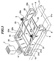
- FIG. 3 is a perspective view of a slider.
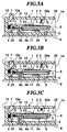
- FIGS. 4A to 4C and FIGS. 5A to 5C are cross-sectional views of the card connector, which are useful in explaining the operation of the same.
- the card connector is comprised of a box-shaped insulator 1, a slider 2 movably accommodated within the insulator 1, coil springs (first urging member) 3, 3 for urging the slider 2 against a bottom wall 11 of the insulator 1, a coil spring (second urging member) 4 for urging the slider 2 toward an insertion opening 14 of the insulator 1 via which a miniature card 8 is inserted into the card connector, projections 5, 5 provided at respective lower portions of a rear end of the slider 2, holes (recesses) 6, 6 formed through a bottom wall 11 of the insulator 1, and an ejector button (card-ejecting means) 7 for disengaging a recessed terminal array portion 8a of the miniature card 8 from a protruded terminal array portion 9a of a circuit board 9, on which the recessed terminal array portion 8a is fitted.
- the slider 2 is constituted by side plates 20, 21 which are opposed to each other in a direction perpendicular to a card-inserting direction A in a manner spaced from each other by a predetermined distance, an upper bridge 23 stretching between a portion of the top of the side plate 20 and a portion of the top of the side plate 21, a lower bridge 24 stretching between a portion of the bottom of the side plate 20 and a portion of the bottom of the side plate 21, and a front plate 25 stretching between a front end 20d of the side plate 20 and a front end 21d of the side plate 21.
- the bottom of the front plate 25 is in contact with the bottom wall 11 of the insulator 1.
- the side plate 20 and the side plate 21 have a projection 20a and a projection 21a integrally formed therewith and extending upward from respective portions of their tops.
- the coil springs 3, 3 are fixed to the projections 20a, 21a, respectively, and slide in unison with the slider 2.
- the side plates 20 and 21 have projections 5, 5 integrally formed therewith at respective lower portions of a rear end 20c and a rear end 21c thereof.
- the projections 5, 5 are in contact with the bottom wall 11 of the insulator 1.
- the front ends 20d, 21d of the side plates 20, 21 are formed with elongate guide slots 20b, 21b, and pins 15 fixed to opposed side walls 12 of the insulator 1 are inserted into the elongate guide slots 20b, 21b, respectively.
- the insulator 1 has a top wall 10, the bottom wall 11, the side walls 12, an innermost wall 13, and the insertion opening 14.
- the top wall 10 is formed with a through hole 10a in which the ejector button 7 is slidably mounted.
- the ejector button 7 is constantly urged upward by a return spring, not shown.
- the projections 5, 5 of the slider 2 correspond in position to the holes 6, 6 of the bottom wall 11 of the insulator 1 and hence are caused to drop therein by the urging forces of the coil springs 3.
- the above-mentioned spring 4 is arranged between the innermost wall 13 of the insulator 1 and the front plate 25 of the slider 2.
- the recessed terminal array portion 8a of the miniature card 8 has sixty signal electrodes or contacts.
- the protruded terminal array portion 9a of the circuit board 9 is constituted by layers of electrically conductive rubber and layers of an insulator joined such that exposed portions of the conductive layers correspond respectively to the sixty signal electrodes of the miniature card 8.
- the miniature card 8 is inserted from the insertion opening 14 (see FIG. 4A) and guided into inner pert of the insulator 1 by the side plates 20, 21 and the bridges 23, 24 of the slider 2.
- the miniature card 8 and the slider 2 are moved together in the insulator 1 in the card-inserting direction A (see FIG. 4C).
- the coil springs 3 constantly urge the slider 2 against the bottom wall 11 of the insulator 1, and when the recessed terminal array portion 8a of the miniature card 8 is brought to a position exactly above the protruded terminal array portion 9a of the circuit board 9, the projections 5, 5 of the slider 2 are caused to drop into the holes 6, 6 formed in the bottom wall 11 of the insulator 1 (see FIG. 5A by the downward urging forces of the coil springs 3). As a result, the slider 2 is brought into an inclined position, thereby fitting the recessed terminal array portion 8a of the miniature card 8 on the protruded terminal array portion 9a of the circuit board 9 to effect electrical connection between the miniature card 8 end the circuit board 9.
- the ejector button 7 is depressed.
- the front plate 25 of the slider 2 is located exactly under the ejector button 7 (see FIG. 5A), and hence by depressing the ejector button 7, the bottom of the ejector button 7 abuts against the front plate 25 of the slider 2 (see FIG. 5B) end pushes it downward, whereby the slider 7 is brought into a level position (see FIG. 5C) together with the miniature card 8 carried on the lower bridge 24 of the slider 2.
- the recessed terminal array portion 8a of the miniature card 8 is disconnected from the protruded terminal array portion 9a of the circuit board 9, and both the slider 2 end the miniature card 8 are pushed back in the direction of the insertion opening 14 by the urging force of the spring 4.
- the miniature card 8 can be inserted and removed from a side of the insulator 1 (the insertion opening 14 opening at one of the four sides of the insulator 1, in the present embodiment) without deforming the protruded terminal array portion 9a of the circuit board 9. Therefore, when this card connector is employed e.g. for a digital still camera, the insertion and removal of the miniature card 8 can be performed via one of the sides of a camera casing, thereby permitting a whole top surface of the camera casing to be used as a space for mounting a liquid crystal display panel. This makes it possible to mount a large-sized liquid crystal display panel in the digital still camera without increasing the size of the casing thereof.
- FIGS. 6 and 7 are cross-sectional views of a card connector according to a second embodiment of the invention.
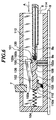
- FIG. 6 is a cross-sectional view showing a state in which a card is being inserted into the card connector
- FIG. 7 is a cross-sectional view showing a state in which the card has been inserted into the same.
- the arrangement of the guide and support means of the miniature card 8 is not shown in the figures. Component parts and elements corresponding to those of the first embodiment are designated by identical or similar reference numerals, and description thereof is omitted.
- the card connector is comprised of a hollow insulator 100, a slider 102 movably accommodated within the insulator 101, a pivotally movable member 100 pivotally secured to an inner wall surface of the insulator 101 by a pivot 126, a spring (first urging member) 103 for constantly urging the pivotally movable member 100 in a clockwise direction (predetermined direction of pivotal movement of the pivotally movable member) as viewed in FIG.
- a recess 106 formed in a bottom 102b of the slider 102 an ejector button (card-ejecting means) 7 for disengaging a recessed terminal array portion 8a of a miniature card 8 from a protruded terminal array portion 9a of a circuit board 9 fitted therein, and a spring (second urging member) 104 for constantly urging the slider 102 toward an insertion opening 114 of the insulator 101.
- the pivotally movable member 100 has a front end 100a having a downwardly protruded portion 110a integrally formed with an engaging portion 110 which extends inward from the portion 110a, i.e. in a direction away from the inner wall surface to which the pivotally movable member 100 is secured.
- the engaging portion 110 corresponds in position to the recess 106 of the bottom 102b of the slider 102 when the recessed terminal array portion 8a of the miniature card 8 guided by the slider 102 is at a position exactly above the protruded terminal array portion 9a of the circuit board 9.
- the pivotally movable member 100 also has a rear end 100b having a downwardly protruded portion 120a integrally formed with a depressing portion 120 for depressing the miniature card 8,which extends inward from the portion 120a i.e. in the direction away from the inner wall to a transverse position corresponding to the miniature card 8 when it is inserted. Further, the slider 102 is inhibited from moving upward by two slider guides, not shown, formed integrally with an inner wall of the insulator 101 opposite to the inner wall to which the pivotally movable member 100 is secured, such that the slider guides extend inward therefrom.
- the miniature card 8 When the miniature card 8 is inserted from the insertion opening 114, first, the front end of the miniature card 8 abuts against a rear end 102a of the slider 102 (see FIG. 6). Then, the miniature card 8 and the slider 102 are moved together in a card-inserting direction A within the insulator 101.
- the spring 103 constantly urges the pivotally movable member 100 in the clockwise direction as viewed in FIG. 6, and hence when the recessed terminal array portion 8a of the miniature card 8 is brought to a position exactly above the protruded terminal array portion 9a of the circuit board 9, the engaging portion 110 of the pivotally movable member 100 is fitted in the recess 106 formed in the bottom 102b of the slider 102 whereby the pivotally movable member 100 pivotally moves about the pivot 126 in the clockwise direction as viewed in FIG. 6 so that the depressing portion 120 of the pivotally movable member 100 pushes down the miniature card 8 (see FIG. 7).
- the recessed terminal array portion 8a of the miniature card 8 is fitted on the protruded terminal array portion 9a of the circuit board 9 to thereby electrically connect the two terminal array portions.
- the ejector button 7 is depressed.
- the front end 100a of the pivotally movable member 100 is located exactly under the ejector button 7, and hence when the ejector button 7 is depressed, the bottom of the ejector button 7 pushes down the front end 100a of the pivotally movable member 100, whereby the pivotally movable member 102 is moved about the pivot 126 in a counterclockwise direction as viewed in FIG. 6 to disengage the engaging portion 110 of the pivotally movable member 100 from the recess 106 formed in the bottom 102b of the slider 102 and at the same time the depressing portion 120 of the pivotally movable member 100 moves array from the miniature card 8.
- the downward urging force of the depressing portion 120 of the pivotally movable member 100 ceases to be applied to the miniature card 8, so that the miniature card 8 is moved upward by upward-urging means, not shown, to have the recessed terminal array portion 8a disengaged from the protruded terminal array portion 9a of the circuit board 9, and is pushed back toward the insertion opening 114 of the insulator 101 by the urging force of the spring 104 via the slider 102.
- the above card connector according to the second embodiment provides the same effects as obtained by the card connector according to the first embodiment.
- FIGS. 8 and 9 are cross-sectional views of a card connector according to a third embodiment of the invention.
- FIG. 8 is a cross-sectional view showing a state where a card is being inserted into the card connector.
- FIG. 9 is a cross-sectional view showing a state where the card has been inserted into the card connector.
- Component parts and elements corresponding to those of the above embodiment are designated by identical or similar reference numerals, end description thereof is omitted.
- This card connector is comprised of a hollow insulator 201, a slider 202 which is capable of moving in the insulator 201 with a flexible printed cable (hereinafter referred to as "the FPC") 209 carried thereon, a spring (urging member) 204 for urging the slider 202 in an opposite direction to the card-inserting direction A, a flexible member 230 integrally connected to the slider 202 for supporting a protruded terminal array portion 209a of the FPC 209 from underside thereof, a recess 231 formed in a bottom 211 of the insulator 201 such that it extends toward an insertion opening 214 of the insulator 201, a locking projection 230a formed on the bottom of the flexible member 230, and a locking recess 211a formed in the bottom 211 of the insulator 201 for looking the miniature card 8 such that when the protruded terminal array portion 209a of the FPC 209 is fitted in the recessed terminal array portion 8a of the miniature card 8, the locking
- the flexible member 230 is integrally connected to a portion of a rear end of the slider 202.
- the flexible member 230 When the flexible member 230 is positioned on a flat pert of the bottom 21 inward of the recess 231, the flexible member 230 extends toward the insertion opening 214 in parallel with a rearward-extended flat portion 202c of the slider 202.
- the rearward-extended flat portion 202c supports the miniature card 8 inserted into the card connector 8 such that the recessed terminal array portion 8a of the miniature card 8 can be accessed from below.
- the slider 202 includes an abutment portion 202a against which the miniature card 8 abuts when it is inserted into the card connector and a spring-receiving portion 202b receiving the spring 204.
- the location of the protruded terminal array portion 209a of the FPC 209 corresponds to the position of the recessed terminal array portion 8a of the miniature card 8 when it abuts the abutment portion 202a of the slider
- the FPC 209 has one end portion thereof held on the slider 202 and another end portion thereof slidably supported by a through hole 213a formed through an innermost wall 213 of the insulator 201.
- the spring 204 is arranged between the spring-receiving portion 202b of the slider 202 and the innermost wall 213 of the insulator 201.
- the recess 231 is formed with a sloped guide face 231a, and progressively becomes deeper as it extends from the locking recess 211a outward toward the insertion opening 214.
- the looking projection 230a of the flexible member 230 and the locking recess 211a formed in the bottom 211 of the insulator 201 forms locking means.
- the miniature card 8 When the miniature card 8 is inserted via the insertion opening 214, first, a front end thereof abuts against the abutment portion 202a of the slider 202 (see FIG. 8). At this time point, the flexible member 230 and the one end portion of the FPC 209 are parallel to the sloped guide face 231a of the recess 231, so that the protruded terminal array portion 209a of the FTC 209 is positioned away from the recessed terminal array portion 8a of the miniature card 8, i.e. down in the recess 231. Therefore, before the inserted miniature card 8 abuts against the slider 202, the miniature card 8 is not brought into contact with the protruded terminal array portion 209a of the FPC 209.
- the miniature card 8 is further inserted against the urging force of the spring 209 applied to the slider 202 in a direction opposite to the card-inserting direction A whereby the slider 202 and the FPC 209 are moved in this direction, i.e. leftward as viewed in FIG. 8.
- the protruded terminal array portion 209a of the FPC 209 is moved upward along the sloped guide face 231a, and at the same time the locking projection 230a of the flexible member 230 is also moved upward along the sloped guide face 231a until the FPC 209 and the flexible member 230 becomes parallel to the flat part of the bottom 211 of the insulator 201.
- Part of the FPC 209 is pushed out of the insulator 201 from the through hole 213a thereof and bent
- the protruded terminal array portion 209a of the FPC 209 is fitted in the recessed terminal array portion 8a of the miniature card 8, and at the same time the looking projection 230a of the flexible member 230 is fitted in the locking recess 211a formed in the flat part of the bottom 211 of insulator 201 (see FIG. 9).
- the locking projection 230a of the flexible member 230 is fitted in the locking recess 211a, whereby a state in which the protruded terminal array portion 209a of the FPC 209 is fitted in the recessed terminal array portion 8a of the miniature card 8 is maintained against the urging force of the spring 204.
- the miniature card 8 and the FPC 209 are electrically connected to each other.
- an ejection device not shown, is operated.
- the injection device is operated to move the flexible member 230 upward, the locking projection 230a of the flexible member 230 is disengaged from the locking recess 211a, and the miniature card 8 is pushed back in the direction of the insertion opening 214 by the urging force of the spring 204.
- the flexible member 230 and the protruded terminal array portion 209a of the FPC 209 are moved downward along the sloped guide face 231a, whereby the protruded terminal array portion 209a of the FPC 209 is moved down into the recess 231.
- the recessed terminal array portion 8a of the miniature card 8 is disengaged from the protruded terminal array portion 209a of the FPC 209 and only the miniature card 8 on the rear-extended portion 202c of the slider 202 is pushed back through the insertion opening 214.
- the card connector according to the third embodiment provides the same effects as obtained by the card connector according to the first embodiment.
- FIGS. 10 to 12 are cross-sectional views of a card connector according to a fourth embodiment of the invention.
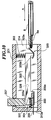
- FIG. 10 is a cross-sectional view showing a state in which a miniature card starts to be inserted into the card connector.
- FIG. 11 is a cross-sectional view showing a state in which the miniature card is being inserted into the same.
- FIG. 12 is across-sectional view showing a state in which the miniature card has been inserted into the same.
- the arrangement of the guide and support means of the miniature card 8 is not shown in the figures. Component parts and elements corresponding to those of the above-mentioned embodiments are designated by identical or similar reference numerals, and description thereof is omitted.
- This card connector is comprised of a hollow insulator 301, a pivotally movable member 300 pivotally secured to an inner wall surface of the insulator 301 by a pivot 326, a spring (first urging member ) 303 for urging the pivotally movable member 300 in a clockwise direction (predetermined direction of pivotal movement) as viewed in FIG.
- a lifting member 320 attached to the bottom of one end of the pivotally movable member 300 and extending inward therefrom, a support member 330 attached to the bottom of another end of the pivotally movable member 300 and extending inward therefrom, for supporting the protruded terminal array portion 209a of the FPC 209 from underside thereof, a spring (second urging member) 304 for urging the miniature card 8 in a direction opposite to a card-inserting direction A, an ejector button (card-ejecting means) 307 which pivotally moves the pivotally movable member 300 in an counterclockwise direction (direction opposite to the predetermined direction of the pivotal movement) as viewed in FIG.10 to thereby disengage the protruded terminal array portion 209a of the FPC 209 from the recessed terminal array portion 8a of the miniature card 8.
- the lifting member 320 includes a lifter plate portion 320a inclined with respect to the card-inserting direction A and projecting upward toward an insertion opening 314 of the insulator 301 and an engaging plate portion 320b inclined with respect to the card-inserting direction A and projecting upward in a direction away from the insertion opening 314.
- the protruded terminal array portion 209a of the FPC 209 is supported by the support member 330, while the remaining portion of the FPC 209 extends outward through a through hole 313a formed through an innermost wall 313 of the insulator 301.
- the pivotally movable member 300 is maintained in a generally horizontal position by the coil spring 303. Further, one end of the coil spring 304 abuts against the protruded terminal array portion 209a of the FPC 209 via a plate 322.
- the lifting member 320 of the pivotally movable member 300 is lifted by the inserted miniature card 8 to thereby pivotally move the pivotally movable member 300 about the pivot 326 in an counterclockwise direction as viewed in FIG.10 (see FIG. 11) to be inclined with respect to the card-inserting direction A, so that the lifting member 320 of the pivotally movable member 300 is relatively slid on the top of the miniature card 8.
- the front end of the miniature card 8 abuts against the plate 322, and the miniature card 8 is further inserted against the urging force of the coil spring 304.
- the pivotally movable member 300 is inclined with respect to the card-inserting direction A and the support member 330 supporting the protruded terminal array portion 209a of the FPC 209 is moved downward, so that the front and of the miniature card 8 does not run against the protruded terminal array portion 209a.
- the coil spring 303 constantly urges the pivotally movable member 300 in the clockwise direction as viewed in FIG. 10 and hence when the recessed terminal array portion 8a of the miniature card 8 is brought to a position exactly above the protruded terminal array portion 209a of the FPC 209, the pivotally movable member 300 is pivotally moved in the clockwise direction as viewed in FIG. 10 to receive the protruded terminal array portion 209a of the FPC 209 in the recessed terminal array portion 8a of the miniature card 8(see FIG. 12) whereby the two terminal array portions 209a, 8a are engaged with each other to effect electrical connection of them.
- the engaging plate portion 320b of the lifting member 320 engages a lower portion of a rear end of the miniature card 8.
- a rotation moment of the pivotally movable member 300 in the clockwise direction as viewed in Fig.12 and a rotation moment of the same in the counterclockwise direction as viewed in the same are balanced whereby the pivotally movable member 300 is held in a horizontal position.
- the ejector button 307 is depressed.
- the one end 300a of the pivotally movable member 300 is located exactly under the ejector button 307, so that when the ejector button 307 is depressed, the bottom of the ejector button 307 pushes the one end 300a of the pivotally movable member 300 downward.
- the pivotally movable member 300 is pivotally moved in the counterclockwise direction as viewed in FIG.
- the card connector according to the fourth embodiment provides the same effects as obtained by the card connector according to the first embodiment.
- FIGS. 13 and 14 are cross-sectional views of a card connector according to a fifth embodiment of the invention.
- FIG. 13 is a cross-sectional view showing a state in which a miniature card is being inserted into the card connector.
- FIG. 14 is a cross-sectional view showing a state in which the miniature card has been inserted into the same.
- Component parts and elements corresponding to those of the above-mentioned embodiments are designated by identical or similar reference numerals, and description thereof is omitted.
- This card connector is comprised of a hollow insulator 401, a slider 402 movably accommodated within the insulator 401, a recess 402a formed in the top of the slider 402, a pivotally movable member 400 pivotally secured to an inner wall surface of the insulator 401 by a pivot 426, a spring (first urging member) 403 for urging the pivotally movable member 400 in a counterclockwise direction (predetermined direction of pivotal movement) as viewed in FIG.
- an engaging member 420 which is attached to the bottom of one end 400a of the pivotally movable member 400 in a manner enclosing a convex portion 420a formed at the bottom of the one end 400a and extends inward therefrom to a location corresponding in transverse position to the recess 402a of the top of the slider 402, a support member 406 which is attached to the bottom of a downward protruded portion 406a of the other end 400b of the pivotally movable member 400 and extends therefrom inward to the protruded terminal array portion 209a of the FPC 209 to support the same from underside thereof, an ejector button (card-ejecting means) 407 for pivotally moving the pivotally movable member 400 in the clockwise direction (direction opposite to the predetermined direction of the pivotal movement) as viewed in FIG.
- a support member 406 which is attached to the bottom of a downward protruded portion 406a of the other end 400b of the pivotally movable member 400
- One end (protruded terminal array portion 209a) of the FPC 209 is supported from underside thereof by the support member 406, while the other end of the FPC 209 slidably extends through a through hole 413a of the insulator 401.
- the spring 404 is arranged between the slider 402 and an innermost wall 413 of the insulator 401.
- the front end of the miniature card 8 abuts against a rear end 410 of the slider 402 (see FIG. 13).
- the engaging member 420 of the pivotally movable member 400 is located on the top of the slider 402 and the pivotally movable member 400 is inclined with respect to the card-inserting direction A.
- the miniature card 8 and the slider 402 are moved together in the card-inserting direction A within the insulator 401. Since the pivotally movable member 400 is inclined with respect to the card-inserting direction A and the support member 406 supporting the protruded terminal array portion 209a thereon is in a downward-shifted position, so that the front end of the miniature card 8 does not abut against the protruded terminal array portion 209a of the FPC 209.
- the engaging member 420 of the pivotally movable member 400 is fitted in the recess 406 of the top of the slider 402 and the pivotally movable member 400 is pivotally moved about the pivot 426 in the counterclockwise direction as viewed in FIG. 13, so that the support member 405b lifts the protruded terminal array portion 209a of the FPC 209 to thereby fit or engage the protruded terminal array portion 209a of the FPC 209 in the recessed terminal array portion 8a of the miniature card 8 (see FIG. 14), i.e. effect engagement of the two terminal array portions 209a and 8a.
- the engagement of the engaging member 420 of the pivotally movable member 400 in the recess 406 of the slider 402 holds the pivotally movable member 400 in a horizontal position, so that the engagement of the recessed terminal array portion 8a of the miniature card 8 and the protruded terminal array portion 209a of the FPC 209 is maintained against the urging force of the spring 404 to thereby maintain electrical connection of the two terminal array portions.
- the ejector button 407 is depressed. Since the other end 400b of the pivotally movable member 400 is located exactly under the ejector button 407, when the ejector button 407 is depressed, the bottom of the ejector button 407 pushes the other end 400b of the pivotally movable member 400 downward. As a result, the pivotally movable member 400 is pivotally moved in the clockwise direction as viewed in FIG.
- the miniature card 8 is pushed back in the direction of the insertion opening 414 of the insulator 401 by the urging force of the spring 404 applied thereto via the slider 402.
- the card connector according to the fifth embodiment provides the same effects as obtained by the card connector according to the first embodiment.
- FIG. 15 is a cross-sectional view showing a metal protruded terminal array portion for a circuit board other than one employed in the above embodiments.
- This metal terminal is comprised of an insulator 200 and contacts 300a, 300b inserted into holes 200a, 200b formed through the insulator 200.
- the contacts 300a, 300b are formed by bending an electrically conductive metal into a predetermined shape so as to obtain the resilient properties.
- a card can be inserted therein and removed therefrom via one of the sides of an insulator thereof without deforming a protruded terminal array portion of a circuit board or a flexible printed cable contained therein. Therefore, when this card connector is applied to a digital still camera, the card can be inserted and removed from one of the sides of the camera casing, which enables the whole top surface of the camera casing to be utilized as a space for mounting a liquid crystal display panel, and therefore it is possible to mount a large-sized liquid crystal display panel in the digital still camera without increasing the size of the casing thereof.
Landscapes
- Engineering & Computer Science (AREA)
- Physics & Mathematics (AREA)
- General Physics & Mathematics (AREA)
- Theoretical Computer Science (AREA)
- Artificial Intelligence (AREA)
- Computer Vision & Pattern Recognition (AREA)
- Coupling Device And Connection With Printed Circuit (AREA)
Applications Claiming Priority (6)
| Application Number | Priority Date | Filing Date | Title |
|---|---|---|---|
| JP9147290A JPH10321321A (ja) | 1997-05-21 | 1997-05-21 | ミニチュアカードコネクタ |
| JP147290/97 | 1997-05-21 | ||
| JP14729097 | 1997-05-21 | ||
| JP160421/97 | 1997-06-03 | ||
| JP16042197 | 1997-06-03 | ||
| JP9160421A JPH10335026A (ja) | 1997-06-03 | 1997-06-03 | カード用コネクタ |
Publications (2)
| Publication Number | Publication Date |
|---|---|
| EP0880200A2 true EP0880200A2 (de) | 1998-11-25 |
| EP0880200A3 EP0880200A3 (de) | 2001-04-25 |
Family
ID=26477887
Family Applications (1)
| Application Number | Title | Priority Date | Filing Date |
|---|---|---|---|
| EP98303504A Withdrawn EP0880200A3 (de) | 1997-05-21 | 1998-05-05 | Speicherkartensteckverbinder |
Country Status (4)
| Country | Link |
|---|---|
| US (2) | US6089895A (de) |
| EP (1) | EP0880200A3 (de) |
| SG (1) | SG71781A1 (de) |
| TW (1) | TW369739B (de) |
Families Citing this family (12)
| Publication number | Priority date | Publication date | Assignee | Title |
|---|---|---|---|---|
| US6325653B1 (en) * | 1999-07-15 | 2001-12-04 | Kabushiki Kaisha Yokowo | Terminal connecting apparatus for storage device |
| JP4247348B2 (ja) * | 1999-09-20 | 2009-04-02 | モレックス インコーポレイテド | カード用コネクタ |
| FR2803110B1 (fr) * | 1999-12-22 | 2002-05-17 | Framatome Connectors Int | Connecteur pour carte a microcircuit et procede de montage d'une telle carte dans ce connecteur |
| GB2391989B (en) * | 2001-04-12 | 2004-12-01 | Sankyo Seiki Seisakusho Kk | Card forcible ejection mechanism |
| US6796842B1 (en) * | 2003-10-08 | 2004-09-28 | Ming-Te Wang | Electronic card connector |
| TWM293555U (en) * | 2006-02-07 | 2006-07-01 | Tai Sol Electronics Co Ltd | Compact card connector |
| TWM328097U (en) * | 2007-08-24 | 2008-03-01 | Tai Sol Electronics Co Ltd | Card connector with ascendant board |
| US7690935B2 (en) * | 2007-12-14 | 2010-04-06 | Nokia Corporation | Connector structure |
| US10046241B1 (en) * | 2010-11-01 | 2018-08-14 | Ronald Charles Krosky | Output production |
| TWM420080U (en) * | 2011-06-29 | 2012-01-01 | Tai Sol Electronics Co Ltd | Card connector capable of ejecting tray by inserting pin |
| KR101531865B1 (ko) * | 2014-05-29 | 2015-06-26 | (주)우주일렉트로닉스 | 버튼 타입 카드 취출 수단을 구비한 듀얼 메모리 카드용 소켓 |
| US11794107B2 (en) * | 2020-12-30 | 2023-10-24 | Activision Publishing, Inc. | Systems and methods for improved collision detection in video games |
Family Cites Families (12)
| Publication number | Priority date | Publication date | Assignee | Title |
|---|---|---|---|---|
| FR2492213A1 (fr) * | 1980-10-15 | 1982-04-16 | Labo Electronique Physique | Boitier pour carte porteuse d'information muni d'un systeme de verrouillage de ladite carte |
| DE3235654A1 (de) * | 1982-09-27 | 1984-03-29 | Siemens AG, 1000 Berlin und 8000 München | Kontaktiereinrichtung fuer eine steckkarte |
| DE3445185A1 (de) * | 1984-12-11 | 1986-06-12 | Nixdorf Computer Ag, 4790 Paderborn | Aufnahmeeinheit fuer eine einen elektronischen schaltkreis enthaltende datenkarte |
| US4931622A (en) * | 1985-08-09 | 1990-06-05 | Daiichi Denshi Kogyo Kabushiki Kaisha | Electronic card receiving device and ejection mechanism |
| DE3546780C2 (de) * | 1985-09-02 | 1996-04-25 | Amphenol Corp | Kontaktiereinrichtung für eine Chipkarte |
| DE3645268C2 (de) * | 1986-01-29 | 1996-08-14 | Amphenol Corp | Kartenaufnehmner für ein Lesegerät für eine Chip-Karte |
| FR2594988B1 (fr) * | 1986-02-21 | 1989-11-24 | Radiotechnique Ind & Comm | Appareil pour etablir des transferts de donnees avec une carte electronique portative |
| DE3618091C1 (de) * | 1986-05-30 | 1987-09-10 | Allied Corp., Morristown, N.J., Us | |
| JPH0326628Y2 (de) * | 1986-06-24 | 1991-06-10 | ||
| US4904852A (en) * | 1986-12-12 | 1990-02-27 | Omron Tateisi Electronics Co. | IC card reader |
| US4839509A (en) * | 1987-06-19 | 1989-06-13 | Diesel Kiki Co., Ltd. | Connector device for connecting IC card to reading and/or writing apparatus |
| JPH0418235Y2 (de) * | 1988-04-08 | 1992-04-23 |
-
1998
- 1998-04-06 US US09/056,200 patent/US6089895A/en not_active Expired - Fee Related
- 1998-04-09 SG SG1998000820A patent/SG71781A1/en unknown
- 1998-05-05 EP EP98303504A patent/EP0880200A3/de not_active Withdrawn
- 1998-05-20 TW TW087107854A patent/TW369739B/zh active
-
2000
- 2000-01-12 US US09/481,945 patent/US6174186B1/en not_active Expired - Fee Related
Also Published As
| Publication number | Publication date |
|---|---|
| EP0880200A3 (de) | 2001-04-25 |
| TW369739B (en) | 1999-09-11 |
| SG71781A1 (en) | 2000-04-18 |
| US6174186B1 (en) | 2001-01-16 |
| US6089895A (en) | 2000-07-18 |
Similar Documents
| Publication | Publication Date | Title |
|---|---|---|
| US8113871B2 (en) | Connector assembly | |
| US7512397B2 (en) | Battery cover assembly | |
| US6976879B2 (en) | Card connector | |
| KR100865610B1 (ko) | 카드용 커넥터 | |
| US6616473B2 (en) | Thin-type electrical connector having a locking function | |
| CN100357854C (zh) | 端口复制器 | |
| US6089895A (en) | Card connector | |
| KR101472663B1 (ko) | 전기 커넥터 | |
| EP1162701A2 (de) | Kartenverbinder | |
| KR101882622B1 (ko) | 전기 커넥터 | |
| US20020079202A1 (en) | Switch exhibiting non-unidirectional displacement | |
| US5571025A (en) | Circuit board electrical connector | |
| CN112688101A (zh) | 卡座装置及电子设备 | |
| US7040908B2 (en) | Card connector which can be connected to a plurality of kinds of cards different in width | |
| US5984704A (en) | Zif connector having means for keeping flexible contact sheet in tensile condition | |
| US7722373B2 (en) | Electrical connector with a slidable locking member | |
| CN101283485A (zh) | 连接器 | |
| US7244130B2 (en) | Card connector having ejection mechanism | |
| US7503782B2 (en) | Card connector | |
| JP3884325B2 (ja) | フレキシブルプリント基板接続用コネクタおよび接続用フレキシブルプリント基板 | |
| JP2005044784A (ja) | 異なるメモリカードを収容するメモリカードコネクタ | |
| EP1548897A1 (de) | Kartenverbinder mit Mitteln zur Verhinderung von Ausfall- und Ausstossfehlern bei Karten | |
| US4668036A (en) | Large picture display device | |
| US7604509B2 (en) | Card connector | |
| JP2003036934A (ja) | カードコネクタ |
Legal Events
| Date | Code | Title | Description |
|---|---|---|---|
| PUAI | Public reference made under article 153(3) epc to a published international application that has entered the european phase |
Free format text: ORIGINAL CODE: 0009012 |
|
| AK | Designated contracting states |
Kind code of ref document: A2 Designated state(s): DE FR GB |
|
| AX | Request for extension of the european patent |
Free format text: AL;LT;LV;MK;RO;SI |
|
| PUAL | Search report despatched |
Free format text: ORIGINAL CODE: 0009013 |
|
| AK | Designated contracting states |
Kind code of ref document: A3 Designated state(s): AT BE CH CY DE DK ES FI FR GB GR IE IT LI LU MC NL PT SE |
|
| AX | Request for extension of the european patent |
Free format text: AL;LT;LV;MK;RO;SI |
|
| RIC1 | Information provided on ipc code assigned before grant |
Free format text: 7H 01R 9/09 A, 7H 01R 23/68 B, 7G 06K 13/08 B |
|
| 17P | Request for examination filed |
Effective date: 20011001 |
|
| AKX | Designation fees paid |
Free format text: DE FR GB |
|
| 17Q | First examination report despatched |
Effective date: 20030724 |
|
| GRAP | Despatch of communication of intention to grant a patent |
Free format text: ORIGINAL CODE: EPIDOSNIGR1 |
|
| STAA | Information on the status of an ep patent application or granted ep patent |
Free format text: STATUS: THE APPLICATION IS DEEMED TO BE WITHDRAWN |
|
| 18D | Application deemed to be withdrawn |
Effective date: 20040721 |