EP0880204A2 - Kombinations-Antennensteckdose zum Einbau in eine standardisierte Aufputz- oder Unterputzdose - Google Patents
Kombinations-Antennensteckdose zum Einbau in eine standardisierte Aufputz- oder Unterputzdose Download PDFInfo
- Publication number
- EP0880204A2 EP0880204A2 EP98109181A EP98109181A EP0880204A2 EP 0880204 A2 EP0880204 A2 EP 0880204A2 EP 98109181 A EP98109181 A EP 98109181A EP 98109181 A EP98109181 A EP 98109181A EP 0880204 A2 EP0880204 A2 EP 0880204A2
- Authority
- EP
- European Patent Office
- Prior art keywords
- socket
- circuit board
- bnc
- connection
- antenna
- Prior art date
- Legal status (The legal status is an assumption and is not a legal conclusion. Google has not performed a legal analysis and makes no representation as to the accuracy of the status listed.)
- Withdrawn
Links
Images

Classifications
-
- H—ELECTRICITY
- H01—ELECTRIC ELEMENTS
- H01R—ELECTRICALLY-CONDUCTIVE CONNECTIONS; STRUCTURAL ASSOCIATIONS OF A PLURALITY OF MUTUALLY-INSULATED ELECTRICAL CONNECTING ELEMENTS; COUPLING DEVICES; CURRENT COLLECTORS
- H01R24/00—Two-part coupling devices, or either of their cooperating parts, characterised by their overall structure
- H01R24/38—Two-part coupling devices, or either of their cooperating parts, characterised by their overall structure having concentrically or coaxially arranged contacts
- H01R24/40—Two-part coupling devices, or either of their cooperating parts, characterised by their overall structure having concentrically or coaxially arranged contacts specially adapted for high frequency
- H01R24/52—Two-part coupling devices, or either of their cooperating parts, characterised by their overall structure having concentrically or coaxially arranged contacts specially adapted for high frequency mounted in or to a panel or structure
- H01R24/525—Outlets
-
- H—ELECTRICITY
- H01—ELECTRIC ELEMENTS
- H01R—ELECTRICALLY-CONDUCTIVE CONNECTIONS; STRUCTURAL ASSOCIATIONS OF A PLURALITY OF MUTUALLY-INSULATED ELECTRICAL CONNECTING ELEMENTS; COUPLING DEVICES; CURRENT COLLECTORS
- H01R27/00—Coupling parts adapted for co-operation with two or more dissimilar counterparts
- H01R27/02—Coupling parts adapted for co-operation with two or more dissimilar counterparts for simultaneous co-operation with two or more dissimilar counterparts
-
- H—ELECTRICITY
- H01—ELECTRIC ELEMENTS
- H01R—ELECTRICALLY-CONDUCTIVE CONNECTIONS; STRUCTURAL ASSOCIATIONS OF A PLURALITY OF MUTUALLY-INSULATED ELECTRICAL CONNECTING ELEMENTS; COUPLING DEVICES; CURRENT COLLECTORS
- H01R2107/00—Four or more poles
-
- H—ELECTRICITY
- H01—ELECTRIC ELEMENTS
- H01R—ELECTRICALLY-CONDUCTIVE CONNECTIONS; STRUCTURAL ASSOCIATIONS OF A PLURALITY OF MUTUALLY-INSULATED ELECTRICAL CONNECTING ELEMENTS; COUPLING DEVICES; CURRENT COLLECTORS
- H01R2201/00—Connectors or connections adapted for particular applications
- H01R2201/02—Connectors or connections adapted for particular applications for antennas
-
- H—ELECTRICITY
- H01—ELECTRIC ELEMENTS
- H01R—ELECTRICALLY-CONDUCTIVE CONNECTIONS; STRUCTURAL ASSOCIATIONS OF A PLURALITY OF MUTUALLY-INSULATED ELECTRICAL CONNECTING ELEMENTS; COUPLING DEVICES; CURRENT COLLECTORS
- H01R24/00—Two-part coupling devices, or either of their cooperating parts, characterised by their overall structure
- H01R24/60—Contacts spaced along planar side wall transverse to longitudinal axis of engagement
- H01R24/62—Sliding engagements with one side only, e.g. modular jack coupling devices
Definitions
- Connector elements for consumer electronics devices can IEC or DIN-standardized sockets or plugs, e.g. according to IEC 169/2 or DIN 45325.
- the Connectors can also be designed as so-called F-connectors, i.e. a Have screw sleeve on which the connection counterpart for contacting can be screwed on.
- the applicant Antenna socket consisting of an essentially cylindrical housing with a top on which protrudes or sinks at least one bushing or Connector for a selective output for connection at least of a receiving device is known.
- the antenna socket has at least one input for a coaxial cable that is attached to the housing with a shield clamping part, which is connected via the outer conductor of the Coaxial cable engages and with circuit and / or ground potential leading Housing parts of the antenna socket is connected.
- the center leader is on one Fastened connecting part that forms the signal input or output.
- the above task is based on a combination antenna socket with the features in the preamble of claim 2, characterized solved that the known socket body - for connecting a Subscriber equipment to an outside line of a telecommunications or data network - on a BNC and / or Western socket on the top surface that supports the webs of the Support rings - compared to support rings known per se - at least by Overall height of screw / plug-in terminals of the BNC or Western socket compared to Cover surface of the can body are extended that a circular sector-shaped Board for the connection of the external line is provided that the board on the Top of both the BNC and / or Western jack as well Screw / plug-in terminals for the wires of the trunk line and that the coaxial Project plug / socket connections through openings in the board.
- Claim 1 takes place in the embodiment according to the invention Claim 2 the connection of the supply and discharge coaxial cable House installation and the outside line on the top of the can body.
- the one for the connection of the trunk is required in a structurally simple manner and created in that the can body deeper into the installation opening is transferred.
- the installation conditions in particular with regard to installation depth for standardized flush-mounted boxes or surface-mounted boxes can be.
- Another advantage is that it is possible to use the inventive Combination antenna socket with a cover plate to be provided with Can frame can be mounted according to DIN 79075.
- the above task is based on a combination antenna socket with the features in the preamble of claim 3, characterized solved that the known socket body - for connecting a Subscriber equipment to an outside line of a telecommunications or data network - on the top surface of a BNC and / or Western socket that the overall height of the Cover frame - compared to a known cover frame - at least by the height of screw / plug-in terminals of the BNC or Western socket compared to the top surface of the can body is enlarged that a Circuit board-shaped circuit board provided for the connection of the outside line is that the board on top of both the BNC and / or Western jack as well also carries screw / plug-in terminals for the wires of the exchange line and that the protruding coaxial plug / socket connections through openings in the board.
- the circuit board provided is preferably designed in the shape of a circular sector and carries on the top of both the BNC and / or Western jack as well Screw / plug-in terminals for the wires of the exchange line, the coaxial Project plug / socket connections through openings in the board.
- This Design of the combination antenna socket according to the invention has the Advantage on that the process of wave or reflow soldering for manufacturing the circuit board can be used, so that the manufacturing costs for this are low.
- Another advantage is that both the BNC and / or Western socket as well Screw / plug-in terminals as well as the circuit board on the solid cover (top surface 4) are stored. In combination with the extension of the support bars of the support ring insertion forces are absorbed by the coaxial plug / socket connections; ultimately, as in the subject of claim 1, by solid elements.
- All configurations of the combination antenna socket according to the invention is the modular structure with separation of the satellite and cable connections from the Connections for the trunk line together, so that the special requirements for the different systems, e.g. Interference radiation and avoidance of mutual Influencing, can be fulfilled.
- the infrastructure for the distribution of over Antenna, satellite antenna or trunk line received analog or digital Signals - including a so-called return channel for communication with the Service provider - to be created.
- all configurations of the Combination antenna socket according to the invention has the advantage that Angled plugs can be used so that kinking e.g. the telephone cable is reliably avoided.
- the can body in a development of the invention Hinge and corrugation for one that can be pivoted around the hinge Strain relief bracket, with the circuit board in the area of Strain relief bracket is recessed.
- This configuration makes a reliable unintentionally pulling the relatively thin telephone cable out of the Combination antenna socket according to the invention avoided.
- a corresponding shield or Ground connection of the telephone cable can be realized and the assembly effort is on limited to a simple handle.
- the circuit board Has through hole through which a fastening screw of the cover in a threaded hole of the can body engages. This will cause the circuit board to assemble both by the fit by means of a connector element and by the Fixing screw reliably held in position.
- the Spacer has a screw hole extending in the longitudinal direction and carries a pin which engages in the through hole of the board.
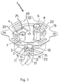
- the combination antenna socket 1 consists of a can body 2, 3 (upper part 3 and lower Part 2), which is cross-divided. These two parts 2, 3 of the can body are in the final assembly, if they are made of plastic, welded and, if they are made of metal, connected to each other so that they can no longer be separated without tools. It is useful Use of metal housing parts to simultaneously shield ensure.
- a support ring 19 is arranged, which For example, screwed or is made in one piece with the can body.
- screws 20 By means of screws 20 and not shown in the drawing expanding claws for example mounting in a flush-mounted box; alternatively, the attachment by means of screws and support ring 19.
- a storage recess 23 are provided, in which the two coaxial, antenna-side Connection cables 12 and 13 are inserted with their ends.
- the ends are secured by the shield clamp 16 held, which is screwed onto the can body surface by means of the screw 17 is.
- a storage chamber 23 can be omitted if the spatial dimensions of the combination antenna socket 1 so dimensioned are that the cables lying on the outside are still in the flush-mounted box can be used.
- the upper housing part 3 also has an extension such a storage chamber 23, in which a connecting part 9 is inserted, the communicates with the circuit board in the upper part 3 of the can body or that the contact sockets of the connecting part 9 are connected to the conductor tracks.
- connection part can also for the coaxial line ends to be connected there, for example the Outgoing coaxial lines of a through box can be provided.
- the Connecting part 9 or this opposite connecting part consist of Insulating material and has known clamping or screw sockets inside in which the stripped center conductors 14, 15 of the cables 13, 12 are inserted and are attached in an electrically conductive manner. These clamping or screw sockets are as previously described, guided inside into the can body 2, 3 and with the corresponding lines of the circuit board connected.
- the jacket of the known and described above Can body 2, 3 - for connecting a subscriber device to a Trunk line 45 of a telecommunications or data network - perpendicular in a partial area flattened to the top surface 4.
- a recess 25 for a vertically rising from the top surface 4 BNC or Western jack 5 provided in the top surface 4 .
- This BNC or Western socket 5 can be connected to the Sidewall in the area of the top surface 4 a collar or web or the like have, which is supported on the top of the top surface 4, and in To this end have a corrugation or locking means or the like offset in the longitudinal direction (not shown in the drawing), which the top surface 4 on the bottom reach around or latch,
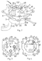
- FIGS. 3 to 9 the combination antenna socket 1 according to the invention shown.
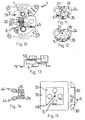
- Fig. 6 and FIG. 7 shows a circuit board 34 for the Connection of the outside line 45 is provided.
- the circuit board 34 carries on the top the BNC socket 5 and on the bottom screw / plug terminals 26 for the Connection of the wires of the outside line 45.
- the printed circuit board 34 Fastening holes 36 arranged in which on the back of the can body 3rd arranged mounting pins 22 (these with or without corrugation and after the Insert bend) intervene and / or there are locking or holding means on the Back of the can body 3 provided (not shown in the drawing), which encompass the circuit board 34 or with which the circuit board 34 is locked, thereby even with frequent or improper use, no deterioration of the Contact reliability or even damage to the printed circuit board 34 is to be expected.
- a lid 39 engages around the bottom of the can body 2 (see Fig. 2), which has an opening 46 for the passage of the trunk 45 and which consists of a plastic material which is in the area of a shielding part 37 is made less thick.
- the first embodiment of the combination antenna socket according to the invention 1 has the advantage that standardized can frames are used can be, in the cover 40 corresponding recesses, for example for the connection of a television set, satellite receiver, Radio and an analog / digital telephone connection (4-hole socket), are provided (see FIGS. 8 and 9); further combinations are e.g. with a 3-hole can to arrange the telephone connection at the location of the satellite connection.
- the cover 40 is fastened through a screw hole 48 by means of a Screw which engages in a threaded hole 49 (see Fig. 3) of the support plate 4. Of the The distance between the support plate 4 and the cover 40 is determined by the spacer 31 ensured (see Fig. 9).
- a centering part 51 is for the western socket 5 (Cover part made of plastic) is provided, which is positive or non-positive with the Cover surface 4 is connected.
- Combination antenna socket which are shown in Figs. 10 to 15 carries the known socket body 2, 3 - for connecting a subscriber device to the outside line 45 of a telecommunications and / or data network - on the top surface 4 a BNC and / or Western socket 5.
- This socket / sockets 5 can / can Area of the cutout 35 and / or in the opposite area (instead of the SAT connection and flattening of the cylindrical box body in this area, SAT socket laid to the side).
- the retaining webs of the support ring 19 are in comparison to known support rings - at least by the height of Screw / plug terminals 26 of the BNC or Western socket 5 opposite the top surface 4 of the Can body 2, 3 extended (see Fig. 13).
- the third embodiment of the combination antenna socket according to the invention 1 is the overall height of the cover frame 30, 33 - compared to a known cover frame - at least by the height of Screw / plug terminals 26 of the BNC or Western socket 5 opposite the top surface 4 of the Can body 2, 3 enlarged (see Fig. 15).
- a circuit board 24 designed for the sector Connection of the outside line 45 is provided (see Fig. 11 and Fig. 12).
- the board 24 carries both the BNC or Western socket 5 and on the top Screw / plug-in terminals 26 for the wires of the exchange line 45 and FIGS. 11 and 12 differ in the different arrangement of the screw / plug-in terminals 26.
- coaxial plug / socket connections 6, 7 through openings protrude through the board 24 and / or have latching or holding means (in the Drawing not shown) and / or on the top surface 4 are locking or holding means provided (not shown in the drawing), which encompass the circuit board 24 or intervene or with which the board 24 is locked, whereby even with frequent or improper use does not degrade contact security or even one Damage to the board 24 is to be expected.
- the opening 18 acts together with the corresponding coaxial Socket connection the positioning of the board 24 by fitting, for example by sawtooth or conical configuration of the opening 18 or alternatively, by arranging an elastic intermediate member in the opening 18. Furthermore, the board 24 has a through hole 27 through which one Fastening screw for the cover in a threaded hole 49 of the can body 3 takes hold. In the assembled state, the strain relief bracket 28 lies under the board 24 and the tensile and plug-in forces occurring during the connection are ultimately from the Cover surface 4 (solid part) caught.
- the strain relief bracket 28 shown in Fig. 14 is on hinge pin 44 on Can body 3 is mounted and points to a corrugation 50 of the can body 3 complementary ribs 29.
- the pivotable strain relief bracket 28 can by means of a countersunk screw is attached to the can body 3 (bore 32); if the strain relief bracket 28 is filled in this area.
- the third embodiment is a two-part cover frame 30, 33 provided with a can frame 30 and with a cover plate 33.
- the height of the cover frame 30, 33 - compared to a known Cover frame - is one arranged on the back of the cover plate 33 Spacers 31 at least by the height of screw / plug terminals 26 BNC socket 5 extended relative to the top surface 4 of the socket body 2, 3 (see Fig. 15.
- the socket 5 can on the side wall in the area of the top surface 4 Have collar or web or the like, which is on the top of the Supports top surface 4, and in the longitudinal direction offset a corrugation or Have locking means or the like (not shown in the drawing), which the Grip or latch cover surface 4 on the underside and / or can This is supplemented by a positive or non-positive connection on the cover frame Support 30, 33.
- the spacer 31 has a length that extends in the longitudinal direction Screw hole 48 and carries a pin which in the through hole 27 of the Board 24 engages.
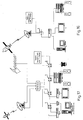
- the combination antenna socket 1 according to the invention is currently distinguished two main areas of application, namely digital pay TV (see Fig. 16) and multi-media PC (see Fig. 17).
- the TV market is expected to move in over the next five to ten years from current free TV to pay TV. With Pay per View, only the fees for the actually seen program counted. Among other things, this should with the help of a Set-top box can be made possible. In it the data about received Shipments saved and regularly e.g. via phone from the relevant provider asked, whereupon the latter can issue the invoice.
- the invention Combination antenna socket 1 (designed as a 2-hole socket according to FIG. 16) offers near the set-top box next to the satellite box also the Possibility of connection to the telephone network.
- FIG. 17 shows the use of the combination antenna socket 1 according to the invention for analog and digital reception with an integrated telephone connection in the form of a 4-hole socket.
- the previous analog signals can also be further processed for user communication with the service provider (teleshopping, video on demand, pay per view, telelearning, Surfing "on the Internet), in addition to the connection for the receiver in the form of the set-top box, a telephone connection for the return channel is made available.
- a private branch exchange (wireless or wired) can also be set up, which is used by all combination antenna sockets 1 according to the invention offers convenient access to the public telecommunications network and at the same time a wide range of free in-house communication options.
Landscapes
- Support Of Aerials (AREA)
Abstract
Description
- Fig. 1
- eine erste perspektivische Ansicht und
- Fig. 2
- eine zweite perspektivische Ansicht einer ersten Ausführungsform der erfindungsgemäßen Kombinations-Antennensteckdose,
- Fig. 3
- die Oberseite und
- Fig. 4
- die Unterseite der ersten Ausführungsform der erfindungsgemäßen Kombinations-Antennensteckdose in Draufsicht,
- Fig. 5
- das Abschirmteil der ersten Ausführungsform der erfindungsgemäßen Kombinations-Antennensteckdose in Draufsicht,
- Fig. 6
- die Leiterplatte in Draufsicht und
- Fig. 7
- die Leiterplatte in Seitenansicht der ersten Ausführungsform der erfindungsgemäßen Kombinations-Antennensteckdose,
- Fig. 8
- die Abdeckung in Draufsicht und
- Fig. 9
- die Abdeckung in Seitenansicht der ersten Ausführungsform der erfindungsgemäßen Kombinations-Antennensteckdose,
- Fig. 10
- die Oberseite der zweiten Ausführungsform der erfindungsgemäßen Kombinations-Antennensteckdose,
- Fig. 11
- die Oberseite einer ersten Ausgestaltung der Platine und
- Fig. 12
- die Oberseite einer zweiten Ausgestaltung der Platine in Draufsicht auf die zweiten Ausführungsform der Kombinations-Antennensteckdose,
- Fig. 13
- im Schnitt eine dritte Ausführungsform der erfindungsgemäßen Kombinations-Antennensteckdose,
- Fig. 14
- die Unterseite eines Zugentlastungsbügels der erfindungsgemäßen Kombinations-Antennensteckdose in Draufsicht,
- Fig. 15
- die Draufsicht sowie die Seitenansicht des Abdeckrahmens für die zweite Ausführungsform der Kombinations-Antennensteckdose,
- Fig. 16
- die Anwendung der erfindungsgemäßen Kombinations-Antennensteckdose bei digitalem Pay-TV und
- Fig. 17
- die Anwendung der Kombinations-Antennensteckdose bei einem sog. Multi-Media-PC mit Internet-Zugang via Satellit.
Hier kann durch eine geeignete Steuerspannung (z.B. 14V/18V) vom Empfangsgerät zwischen horizontaler und vertikaler Polarisation umgeschaltet werden.
Claims (11)
- Kombinations-Antennensteckdose zum Einbau in eine standardisierte Aufputz- oder Unterputzdose, mit einem Haltestege aufweisenden Tragring (19), mit einem zylinderförmigen, hochfrequenzdichten Dosenkörper (2, 3), welcher für den Anschluß der antennenseitigen Koaxialkabel (12, 13) Klemm-/ Schraubverbindungsbuchsen (10, 11), welcher für den Anschluß von Empfangsgeräten auf der Deckfläche (4) angeordnete koaxiale Stecker-/ Buchsenanschlüsse (6, 7) aufweist und der Mantel des Dosenkörpers (2, 3) - für den Anschluß einer Teilnehmereinrichtung an eine Amtsleitung (45) eines Fernmelde- oder Datennetzes - in einem Teilbereich senkrecht zur Deckfläche (4) abgeflacht ist und mit einem ein- oder mehrteiligen Abdeckrahmen (30, 33, 40), dadurch gekennzeichnet, dass in der Deckfläche (4) im Bereich der Abflachung (38) eine Aussparung (25) für eine von der Deckfläche (4) sich senkrecht erhebende BNC- und/oder Western-Buchse (5) vorgesehen ist, dass eine kreissektorförmig ausgestaltete Leiterplatte (34) für den Anschluß der Amtsleitung (45) vorgesehen ist und dass auf der parallel zur Deckfläche (4) verlaufenden Leiterplatte (34) auf der Oberseite die BNC- und/oder Western-Buchse (5) und auf Unterseite Schraub-/ Steckklemmen (26) für die Adern der Amtsleitung (45) angeordnet sind.
- Kombinations-Antennensteckdose zum Einbau in eine standardisierte Aufputz- oder Unterputzdose, mit einem Haltestege aufweisenden Tragring (19), mit einem zylinderförmigen, hochfrequenzdichten Dosenkörper (2, 3), welcher für den Anschluß der antennenseitigen Koaxialkabel (12, 13) Klemm-/ Schraubverbindungsbuchsen (10, 11) und welcher für den Anschluß von Empfangsgeräten auf der Deckfläche (4) angeordnete koaxiale Stecker-/ Buchsenanschlüsse (6, 7) aufweist und mit einem ein- oder mehrteiligen Abdeckrahmen (30, 33, 40), dadurch gekennzeichnet, dass der an sich bekannte Dosenkörper (2, 3) - für den Anschluß einer Teilnehmereinrichtung an eine Amtsleitung (45) eines Fernmelde- oder Datennetzes - auf der Deckfläche (4) eine BNC- und/oder Western-Buchse (5) trägt, dass die Haltestege des Tragrings (19) - im Vergleich zu an sich bekannten Tragringen - mindestens um die Bauhöhe von Schraub-/ Steckklemmen (26) der BNC- oder Western-Buchse (5) gegenüber der Deckfläche (4) des Dosenkörper (2, 3) verlängert sind, dass eine kreissektorförmig ausgestaltete Platine (24) für den Anschluß der Amtsleitung (45) vorgesehen ist, dass die Platine (24) auf der Oberseite sowohl die BNC- und/oder Western-Buchse (5) als auch Schraub-/ Steckklemmen (26) für die Adern der Amtsleitung (45) trägt und dass die koaxialen Stecker-/ Buchsenanschlüsse (6, 7) durch Öffnungen in der Platine (24) hindurchragen.
- Kombinations-Antennensteckdose (1) zum Einbau in eine standardisierte Aufputz- oder Unterputzdose, mit einem Haltestege aufweisenden Tragring (19), mit einem zylinderförmigen, hochfrequenzdichten Dosenkörper (2, 3), welcher für den Anschluß der antennenseitigen Koaxialkabel (12, 13) Klemm-/ Schraubverbindungsbuchsen (10, 11) und welcher für den Anschluß von Empfangsgeräten auf der Deckfläche (4) angeordnete, koaxiale Stecker-/ Buchsenanschlüsse (6, 7) aufweist und mit einem ein- oder mehrteiligen Abdeckrahmen (30, 33, 40), dadurch gekennzeichnet, dass der an sich bekannte Dosenkörper (2, 3) - für den Anschluß einer Teilnehmereinrichtung an eine Amtsleitung (45) eines Fernmelde- oder Datennetzes - auf der Deckfläche (4) eine BNC und/oder Western-Buchse (5) trägt, dass die Bauhöhe des Abdeckrahmens (30, 33) - im Vergleich zu einem an sich bekannten Abdeckrahmen - mindestens um die Bauhöhe von Schraub-/ Steckklemmen (26) der BNC- oder Western-Buchse (5) gegenüber der Deckfläche (4) des Dosenkörper (2, 3) vergrößert ist, dass eine kreissektorförmig ausgestaltete Platine (24) für den Anschluß der Amtsleitung (45) vorgesehen ist, dass die Platine (24) auf der Oberseite sowohl die BNC- und/oder Western-Buchse (5) als auch Schraub-/ Steckklemmen (26) für die Adern der Amtsleitung (45) trägt und dass die koaxialen Stecker-/ Buchsenanschlüsse (6, 7) durch Öffnungen in der Platine (24) hindurchragen.
- Kombinations-Antennensteckdose (1) nach Anspruch 1, dadurch gekennzeichnet, dass in der Leiterplatte (34) mehrere Befestigungslöcher (36) angeordnet sind, in welche auf der Rückseite des Dosenkörpers (3) angeordnete Stifte eingreifen.
- Kombinations-Antennensteckdose (1) nach Anspruch 1, dadurch gekennzeichnet, dass der Dosenkörper (3) ein Scharnier (42) und eine Riffelung (41) für einen um das Scharnier (42) verschwenkbaren Zugentlastungsbügel aufweist und dass die Leiterplatte (34) den Bereich des Zugentlastungsbügels ausspart.
- Kombinations-Antennensteckdose (1) nach Anspruch 2 oder 3, dadurch gekennzeichnet, dass die Platine (24) ein Durchgangsloch (27) aufweist, durch welches eine Befestigungsschraube in ein Gewindeloch (49) des Dosenkörpers (3) greift.
- Kombinations-Antennensteckdose (1) nach Anspruch 6, dadurch gekennzeichnet, dass ein Zugentlastungsbügel (28) über Scharnierzapfen (44) am Dosenkörper (3) gelagert ist und zu einer Riffelung (50) des Dosenkörpers (3) komplementäre Rippen (29) aufweist.
- Kombinations-Antennensteckdose (1) nach Anspruch 3, dadurch gekennzeichnet, dass ein zweiteiliger Abdeckrahmen (30, 33) mit Dosenrahmen (30) und mit Abdeckplatte (33) vorgesehen ist und dass zur Vergrößerung der Bauhöhe des Abdeckrahmens (30, 33) - im Vergleich zu einem an sich bekannten Abdeckrahmen - ein auf der Rückseite der Abdeckplatte (33) angeordneter Abstandshalter (31) mindestens um die Bauhöhe Von Schraub-/ Steckklemmen (26) der BNC- oder Western-Buchse (5) gegenüber der Deckfläche (4) des Dosenkörper (2, 3) verlängert ist.
- Kombinations-Antennensteckdose (1) nach Anspruch 6 und 8, dadurch gekennzeichnet, dass der Abstandshalter (31) ein in Längsrichtung sich erstreckendes Schraubenloch (48) aufweist und einen Zapfen trägt, welcher in das Durchgangsloch (27) der Platine (24) greift.
- Kombinations-Antennensteckdose (1) nach einem der Ansprüche 1 bis 3, dadurch gekennzeichnet, dass den Boden des Dosenkörpers (2) ein Deckel (39) umgreift, welcher eine Öffnung (46) für den Durchtritt der Amtsleitung (45) aufweist und welcher aus einem Kunststoffmaterial besteht, das im Bereich eines Abschirmteils (37) in der Materialstärke geringer ausgeführt ist.
- Kombinations-Antennensteckdose (1) nach einem der Ansprüche 2 oder 3, dadurch gekennzeichnet, dass der Tragring (19) einen Ausschnitt (35) aufweist und dass in diesem Bereich die BNC- oder Western-Buchse (5) angeordnet ist.
Applications Claiming Priority (2)
| Application Number | Priority Date | Filing Date | Title |
|---|---|---|---|
| DE1997121532 DE19721532C2 (de) | 1997-05-22 | 1997-05-22 | Kombinations- Antennensteckdose zum Einbau in eine standardisierte Aufputz- oder Unterputzdose |
| DE19721532 | 1997-05-22 |
Publications (2)
| Publication Number | Publication Date |
|---|---|
| EP0880204A2 true EP0880204A2 (de) | 1998-11-25 |
| EP0880204A3 EP0880204A3 (de) | 1999-11-10 |
Family
ID=7830240
Family Applications (1)
| Application Number | Title | Priority Date | Filing Date |
|---|---|---|---|
| EP98109181A Withdrawn EP0880204A3 (de) | 1997-05-22 | 1998-05-20 | Kombinations-Antennensteckdose zum Einbau in eine standardisierte Aufputz- oder Unterputzdose |
Country Status (2)
| Country | Link |
|---|---|
| EP (1) | EP0880204A3 (de) |
| DE (1) | DE19721532C2 (de) |
Cited By (3)
| Publication number | Priority date | Publication date | Assignee | Title |
|---|---|---|---|---|
| EP1413147A4 (de) * | 2001-02-13 | 2007-03-14 | T M T Third Millenium Technolo | Cableran-vernetzung über koaxialkabel |
| EP1928060A1 (de) * | 2006-11-30 | 2008-06-04 | Elbro AG | Anschlussdosen für Audiosysteme |
| WO2013077755A1 (en) * | 2011-11-22 | 2013-05-30 | Efapel - Empresa Fabril De Produtos Eléctricos, S.A. | Multiple function socket |
Families Citing this family (1)
| Publication number | Priority date | Publication date | Assignee | Title |
|---|---|---|---|---|
| US7517235B2 (en) | 2006-12-28 | 2009-04-14 | General Electric Company | Press fit connection for mounting electrical plug-in outlet insulator to a busway aluminum housing |
Family Cites Families (6)
| Publication number | Priority date | Publication date | Assignee | Title |
|---|---|---|---|---|
| DE2228233A1 (de) * | 1972-06-09 | 1973-12-20 | Siemens Ag | Antennensteckdose |
| DE9110322U1 (de) * | 1991-08-21 | 1991-10-17 | Kurt Wolf GmbH & Co., 7547 Wildbad | Antennensteckdose |
| DE4129293C1 (en) * | 1991-09-03 | 1993-03-04 | Astro Strobel Gmbh & Co. Kg, 5060 Bergisch Gladbach, De | Coaxial antenna socket for wall or flush mounting - accepts cables for radio, TV and satellite set in internal lead running parallel with axis of housing so that support wall does not require place for connections |
| DE4301648C1 (de) * | 1993-01-22 | 1994-06-30 | Technisat Satellitenfernsehpro | Antennensteckdose mit drei oder insbesondere vier Anschlußbuchsen für koaxiale Hochfrequenzstecker zur gleichzeitigen Bereitstellung von terrestrisch empfangenen Signalen und Satellitensignalen |
| DE29505696U1 (de) * | 1995-04-01 | 1995-05-24 | Christian Schwaiger Kg, 90579 Langenzenn | Antennensteckdose |
| DE29618745U1 (de) * | 1996-10-28 | 1997-03-06 | Wilhelm Sihn jr. KG, 75223 Niefern-Öschelbronn | Antennensteckdose |
-
1997
- 1997-05-22 DE DE1997121532 patent/DE19721532C2/de not_active Expired - Lifetime
-
1998
- 1998-05-20 EP EP98109181A patent/EP0880204A3/de not_active Withdrawn
Cited By (3)
| Publication number | Priority date | Publication date | Assignee | Title |
|---|---|---|---|---|
| EP1413147A4 (de) * | 2001-02-13 | 2007-03-14 | T M T Third Millenium Technolo | Cableran-vernetzung über koaxialkabel |
| EP1928060A1 (de) * | 2006-11-30 | 2008-06-04 | Elbro AG | Anschlussdosen für Audiosysteme |
| WO2013077755A1 (en) * | 2011-11-22 | 2013-05-30 | Efapel - Empresa Fabril De Produtos Eléctricos, S.A. | Multiple function socket |
Also Published As
| Publication number | Publication date |
|---|---|
| DE19721532A1 (de) | 1998-11-26 |
| DE19721532C2 (de) | 2002-09-19 |
| EP0880204A3 (de) | 1999-11-10 |
Similar Documents
| Publication | Publication Date | Title |
|---|---|---|
| DE69307620T2 (de) | Koaxialer Verbinder für die Verbindung von zwei Leiterplatten | |
| DE19620834C1 (de) | Einrichtung für Schnurlostelefone | |
| DE60005719T2 (de) | Geerdeter Elektrischer Verbinder mit Kontaktfahnenausrichtung | |
| DE69211833T2 (de) | Installationseinrichtung für Netzanschluss | |
| EP1105947B1 (de) | Anordnung zur übermittlung von nachrichten über ein niederspannungs-stromversorgungsnetz sowie zwischenstück | |
| DE69313553T2 (de) | Anpassungssystem zwischen einem Antennenstecker und der Buchse eines Funktelefons | |
| EP1236247B1 (de) | Anordnung zur übermittlung von nachrichten über ein niederspannungs-stromversorgungsnetz | |
| EP1139493A2 (de) | Elektrischer Verbinder zum Anschluss von elektrischen Leitern an ein elektrisches Gerät | |
| DE19721532C2 (de) | Kombinations- Antennensteckdose zum Einbau in eine standardisierte Aufputz- oder Unterputzdose | |
| DE3723987C2 (de) | ||
| DE9406550U1 (de) | Anschlußdose für Daten- und/oder Kommunikationsnetze | |
| EP0838881B1 (de) | Antennensteckdose | |
| EP1176684B1 (de) | Multimedia-Anschlussdose | |
| DE29709594U1 (de) | Antennensteckdose | |
| EP0973281A1 (de) | Netzfilter und Anschlusskasten mit Netzfilter | |
| DE29505696U1 (de) | Antennensteckdose | |
| EP0902507B1 (de) | Stecker für Koaxialkabel | |
| DE4331143C1 (de) | Anschlußdose zur Bildung einer Anschlußeinrichtung für ein Datennetz | |
| DE10121424C2 (de) | Anschlußeinheit für Telekommunikations- und Datennetze | |
| DE7726413U1 (de) | Einrichtung zur Verteilung von an einer Antennensteckdose auftretenden Signalen auf mehrere Verbraucher | |
| CH684042A5 (de) | Steckdose. | |
| EP1249898A2 (de) | Koaxiale Steckverbindung mit hörbarer Verrastung bei elektrischer Kontaktgabe | |
| DE10339570B4 (de) | Antennensteckdose | |
| DE29507758U1 (de) | Antennensteckdose | |
| DE202024105808U1 (de) | Kabelanschlussdose und elektrisches Gerät mit derselben |
Legal Events
| Date | Code | Title | Description |
|---|---|---|---|
| PUAI | Public reference made under article 153(3) epc to a published international application that has entered the european phase |
Free format text: ORIGINAL CODE: 0009012 |
|
| AK | Designated contracting states |
Kind code of ref document: A2 Designated state(s): AT BE CH CY DE DK ES FI FR GB GR IE IT LI LU MC NL PT SE |
|
| AX | Request for extension of the european patent |
Free format text: AL;LT;LV;MK;RO;SI |
|
| PUAL | Search report despatched |
Free format text: ORIGINAL CODE: 0009013 |
|
| AK | Designated contracting states |
Kind code of ref document: A3 Designated state(s): AT BE CH CY DE DK ES FI FR GB GR IE IT LI LU MC NL PT SE |
|
| AX | Request for extension of the european patent |
Free format text: AL;LT;LV;MK;RO;SI |
|
| RIC1 | Information provided on ipc code assigned before grant |
Free format text: 6H 01R 27/00 A, 6H 01R 13/66 B, 6H 01R 17/12 B, 6H 01R 27/02 B |
|
| AKX | Designation fees paid | ||
| REG | Reference to a national code |
Ref country code: DE Ref legal event code: 8566 |
|
| STAA | Information on the status of an ep patent application or granted ep patent |
Free format text: STATUS: THE APPLICATION IS DEEMED TO BE WITHDRAWN |
|
| 18D | Application deemed to be withdrawn |
Effective date: 20000511 |