EP0880209A2 - Dispositif d'installation - Google Patents
Dispositif d'installation Download PDFInfo
- Publication number
- EP0880209A2 EP0880209A2 EP98109442A EP98109442A EP0880209A2 EP 0880209 A2 EP0880209 A2 EP 0880209A2 EP 98109442 A EP98109442 A EP 98109442A EP 98109442 A EP98109442 A EP 98109442A EP 0880209 A2 EP0880209 A2 EP 0880209A2
- Authority
- EP
- European Patent Office
- Prior art keywords
- signal recording
- installation device
- information
- signal
- units
- Prior art date
- Legal status (The legal status is an assumption and is not a legal conclusion. Google has not performed a legal analysis and makes no representation as to the accuracy of the status listed.)
- Granted
Links
Images


Classifications
-
- H—ELECTRICITY
- H05—ELECTRIC TECHNIQUES NOT OTHERWISE PROVIDED FOR
- H05K—PRINTED CIRCUITS; CASINGS OR CONSTRUCTIONAL DETAILS OF ELECTRIC APPARATUS; MANUFACTURE OF ASSEMBLAGES OF ELECTRICAL COMPONENTS
- H05K7/00—Constructional details common to different types of electric apparatus
- H05K7/14—Mounting supporting structure in casing or on frame or rack
- H05K7/1462—Mounting supporting structure in casing or on frame or rack for programmable logic controllers [PLC] for automation or industrial process control
- H05K7/1481—User interface, e.g. status displays; Programming interface, e.g. connector for computer programming; Monitoring
-
- G—PHYSICS
- G05—CONTROLLING; REGULATING
- G05B—CONTROL OR REGULATING SYSTEMS IN GENERAL; FUNCTIONAL ELEMENTS OF SUCH SYSTEMS; MONITORING OR TESTING ARRANGEMENTS FOR SUCH SYSTEMS OR ELEMENTS
- G05B19/00—Program-control systems
- G05B19/02—Program-control systems electric
- G05B19/04—Program control other than numerical control, i.e. in sequence controllers or logic controllers
- G05B19/042—Program control other than numerical control, i.e. in sequence controllers or logic controllers using digital processors
-
- H—ELECTRICITY
- H05—ELECTRIC TECHNIQUES NOT OTHERWISE PROVIDED FOR
- H05K—PRINTED CIRCUITS; CASINGS OR CONSTRUCTIONAL DETAILS OF ELECTRIC APPARATUS; MANUFACTURE OF ASSEMBLAGES OF ELECTRICAL COMPONENTS
- H05K7/00—Constructional details common to different types of electric apparatus
- H05K7/14—Mounting supporting structure in casing or on frame or rack
- H05K7/1462—Mounting supporting structure in casing or on frame or rack for programmable logic controllers [PLC] for automation or industrial process control
- H05K7/1464—Functional units accommodated in the same PLC module housing
-
- H—ELECTRICITY
- H05—ELECTRIC TECHNIQUES NOT OTHERWISE PROVIDED FOR
- H05K—PRINTED CIRCUITS; CASINGS OR CONSTRUCTIONAL DETAILS OF ELECTRIC APPARATUS; MANUFACTURE OF ASSEMBLAGES OF ELECTRICAL COMPONENTS
- H05K7/00—Constructional details common to different types of electric apparatus
- H05K7/14—Mounting supporting structure in casing or on frame or rack
- H05K7/1462—Mounting supporting structure in casing or on frame or rack for programmable logic controllers [PLC] for automation or industrial process control
- H05K7/1475—Bus assemblies for establishing communication between PLC modules
- H05K7/1479—Bus assemblies for establishing communication between PLC modules including decentralized modules, e.g. connected to other modules using fieldbus
-
- H—ELECTRICITY
- H01—ELECTRIC ELEMENTS
- H01H—ELECTRIC SWITCHES; RELAYS; SELECTORS; EMERGENCY PROTECTIVE DEVICES
- H01H2300/00—Orthogonal indexing scheme relating to electric switches, relays, selectors or emergency protective devices covered by H01H
- H01H2300/03—Application domotique, e.g. for house automation, bus connected switches, sensors, loads or intelligent wiring
-
- Y—GENERAL TAGGING OF NEW TECHNOLOGICAL DEVELOPMENTS; GENERAL TAGGING OF CROSS-SECTIONAL TECHNOLOGIES SPANNING OVER SEVERAL SECTIONS OF THE IPC; TECHNICAL SUBJECTS COVERED BY FORMER USPC CROSS-REFERENCE ART COLLECTIONS [XRACs] AND DIGESTS
- Y02—TECHNOLOGIES OR APPLICATIONS FOR MITIGATION OR ADAPTATION AGAINST CLIMATE CHANGE
- Y02B—CLIMATE CHANGE MITIGATION TECHNOLOGIES RELATED TO BUILDINGS, e.g. HOUSING, HOUSE APPLIANCES OR RELATED END-USER APPLICATIONS
- Y02B90/00—Enabling technologies or technologies with a potential or indirect contribution to GHG emissions mitigation
- Y02B90/20—Smart grids as enabling technology in buildings sector
-
- Y—GENERAL TAGGING OF NEW TECHNOLOGICAL DEVELOPMENTS; GENERAL TAGGING OF CROSS-SECTIONAL TECHNOLOGIES SPANNING OVER SEVERAL SECTIONS OF THE IPC; TECHNICAL SUBJECTS COVERED BY FORMER USPC CROSS-REFERENCE ART COLLECTIONS [XRACs] AND DIGESTS
- Y04—INFORMATION OR COMMUNICATION TECHNOLOGIES HAVING AN IMPACT ON OTHER TECHNOLOGY AREAS
- Y04S—SYSTEMS INTEGRATING TECHNOLOGIES RELATED TO POWER NETWORK OPERATION, COMMUNICATION OR INFORMATION TECHNOLOGIES FOR IMPROVING THE ELECTRICAL POWER GENERATION, TRANSMISSION, DISTRIBUTION, MANAGEMENT OR USAGE, i.e. SMART GRIDS
- Y04S20/00—Management or operation of end-user stationary applications or the last stages of power distribution; Controlling, monitoring or operating thereof
- Y04S20/14—Protecting elements, switches, relays or circuit breakers
Definitions
- the invention relates to an installation device, in particular for a decentralized Building technology, with at least one signal recording and information unit and at least one signal receiving and control unit, between which a Signal exchange takes place.
- Part of the installation equipment consists of the signal generators, for example In the house existing switch devices, which in the simplest case for Switch on the light or to control the blinds, the garage door etc. are used.
- the conventional switches are designed for them conduct the existing mains voltage of 220 volts to the respective end user, being a variety of different switch functions and circuitry exists, which control the light sources or other Enable functions from multiple positions.
- These independent supply network may exist Cabling, which, for example, perform room monitoring or but to control the heating system, the inside and outside temperature to transfer. It is therefore a very great effort to install these devices required to carry out the switching function to be carried out by the signal generator or the Transfer sensors to the end devices.
- the invention has for its object to provide an installation device which is an unproblematic replacement of the existing switch devices while increasing flexibility and shared decentralized Control of independent installation facilities.
- the components of the Signal recording and information units at least on one below the Switch cover attached circuit board or within a compact component, e.g. of hybrid technology.
- the components the signal recording and information units on a first circuit board Wall mounting inside the switch frame cover and a second circuit board are arranged below the switch cover, which are covered by at least one, preferably four plug contact strips arranged in the corner points or Socket strips are interconnected, the plug contact strips and Corresponding socket contact strips perpendicular to the respective board are arranged.
- That kind of Version with two separate boards is particularly advantageous if the Installation facilities through a wired BUS system in the further need to be connected to low voltage lines because first the lower one Board can be attached to the wall and wiring is done before Switch cover with the other board component is plugged on. In the event of Troubleshooting or checking can be done by pulling the switch cover if necessary, the errors can be localized quickly and easily.
- the signal recording and Information unit at least one programmable microprocessor circuit has, which for the acquisition, display and forwarding of measured value, control, optical and acoustic information and / or monitoring signals and Evaluation of the existing signals is provided.
- the signal recording and Information units from switches, in particular device switches, Information displays, room temperature, climate controllers, paging and Signaling devices, alarm system sensors or transmitters, bus inputs, sensors, Dimmers, junction boxes, counters or personal identification devices exist and that the signal receiving and control unit for connection to heating and Industrial water systems, ventilation systems with heat recovery, solar, Lighting, alarm systems, swimming pool controls, technical devices as well acoustic or optical warning and reporting devices is provided.
- a signal recording and information unit of one or is assigned to several signal reception and control units and / or that a signal receiving and control unit of one or more signal recording and Information unit is assigned.
- the optional possibility of Assignment of signal recording and information units and signal reception and Control units for example, have the option of several Rooms or positions to initiate the same control processes, whereby in also several operating devices, for example lighting systems, by one only signal recording and information unit can be controlled.
- By the use of microprocessor technology there is also the possibility that an individual and changeable programming of the assignment between a Signal recording and information unit and a signal receiving and Control unit is possible. Once assigned, the Signal acquisition and information units and the signal reception and Control units can be changed at any time and without much circuitry be, so that the building technology on the one hand quickly to new circumstances can be adapted and on the other hand has a maximum of flexibility.
- the further distant signal recording and information units as well Signal reception and control units via a wire, radio or Infrared connection a fiber optic cable or a power line with each other are connected, under Power-Line a signal connection via the Power lines are to be understood.
- a radio and infrared connection is special advantageous for a later upgrade of the existing building technology or for further reduction of the assembly effort, because in this case on Line connections can be dispensed with entirely. With a new or Initial installation can use the proven wire connection, which, however, only for one in the area of signal reception and control units Low voltage needs to be designed and moreover in conventional Wiring can be done.
- the signal recording and information units, as well as signal receiving and control units, which are further apart, are connected to one another via a, preferably 2-wire, serial LON-BUS ( L ocal O perating N approximately) and via a standardized LONTALK -Protocol exchange data and signals.
- the LON-BUS for a decentralized control system using a standardized LONTALK protocol guarantees sufficient flexibility for the initial installation and later retrofitting of buildings, because a decentralized building management system can be set up with little wiring effort, i.e. only 2-core cables the signal recording and information units can be connected to computer systems and / or telephone or data networks via connection devices, in particular the existing LON-BUS connections.
- the LON-Bus has at least one voltage supply module and / or at least one BUS amplifier.
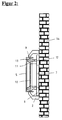
- FIG. 1 shows a top view and a sectional side view of a Signal recording and information unit 1, which as an example Surface switch 2 is shown.
- a Signal recording and information unit 1 which as an example Surface switch 2 is shown.
- the inner one Structure of the signal recording and information unit 1 is further from the cut representation visible.
- a first circuit board 6 is arranged, which, for example, on the the wall to be assembled is screwed on.
- the board 6 also has via a recess 7, which is rectangular or else round can be and offers the possibility of cable routing from below.
- the cables are further fastened in a terminal strip 8, which is on the board 6 is soldered on.
- the rocker 5 is pivotable within the flush-mounted switch cover 2 mounted and has a circumferential collar 9, between which a second circuit board 10 is attached, which the other Components of the signal recording and information units. It is however, it is also conceivable that instead of two boards, only a single board is used.
- the two boards 6 and 10 are via plug contact and Female headers 11, 12 connected to each other, which are perpendicular to the respective board 6, 10 are arranged.
- the plug contact and socket strips 11, 12 enable the movable rocker 5 to be fastened on the one hand lower board 6 and on the other hand via a variety of individual contacts at the same time the necessary electrical connections.
- On the back of the Board 10 are soldered at least two or four buttons 13, which at respond to actuation of rocker 5.
- the arrangement shown is a signal recording and information unit 1 to look at the function and design only as an example, because without further the rocker 5 shown, for example by sensor surfaces, Information displays, control units, dimmers or the like exchanged can be. There is also the option of rocker 5 to be carried out in two parts to perform several switching functions by one To enable signal recording and information unit 1.
- FIG. 2 shows the signal recording and information unit 1 according to the invention again in a sectional view in the assembled state on a Wall 14.
- the execution of the signal recording and information unit 1 corresponds to that of Figure 1.
- the advantage of this type of assembly is that seen from the outside, the switch presents itself as a normal flush-mounted switch, but it is only installed as a surface-mounted switch. This eliminates diverse and useless work, such as electrical, mortising, slot, Masonry, painting work and their subsequent work.
- the invention Signal recording and information units 1 are only with their lower Board 6 and any insulation means on the existing wall screwed on and the concealed switch covers 2 together with the Rocker 5 and the upper board 10 are by means of the plug contact and Socket strips 11, 12 plugged onto the lower board 7. Before the The lower board 7 can possibly be plugged in with the existing ones Lines are connected or else there is a line routing waived and the exchange of the via a radio or infrared connection required signals and data made.
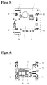
- FIG. 3 shows a top view of the lower board 6 with its recess 7, through which the cables can be passed and into the Screw terminals 8 are attached.
- the Socket strips 12 which are arranged in the vicinity of the board corner points.
- three of them are Female headers 12 aligned horizontally and a fourth vertically.
- a further plug contact strip 15 and socket strip 16 are located on the two opposite side edges and the upper and lower side edges.
- the last-mentioned plug contact and socket strip 15, 16 are for connecting several one above the other or side by side arranged signal recording and information units 1 is provided.
- the individual signal recording and information units 1 are individually on the Fastened to the wall and before assembly by the plug contact and Female headers 15, 16 are connected to each other.
- the arrangement of the Signal recording and information units 1 can be either horizontal or be aligned vertically and using an appropriate Flush-mounted switch cover 3, the plugged-together signal recording and information units 1 are covered.
- Figure 4 shows the upper board 10, which has an upper and lower recess 17, 18 for larger electronic components and on their top is equipped with four individual buttons 13 in the respective corner points.
- the Plug contact strips 11 for connecting to the lower circuit board 6 are located on the bottom and have a corresponding arrangement to the bottom Board 6 on, so that the upper board 10 is plugged in only one position can be.
- the arrangement and Selection of the electronic components on the two boards 6, 10 takes place according to the intended function and usually soften up few identical components.
- FIG. 5 shows a perspective view of the assembled Boards 6, 10 without switch cover and rocker. From the lower board 10 is diametrically opposite on the lower and upper edge of the board Socket strip 15 and plug contact strip 16 for connecting several Signal recording and information units 1 arranged one below the other. in the Furthermore, from the lower board 6, the terminal block 8 for screwing in the Cable connection and the four socket strips located in the corner points 12 shown. In the socket strips 12 are on the back of the top Circuit board 10 correspondingly inserted plug contact strips 11 and thus enable a mechanical and electrical connection of the two boards 6, 10 with each other. In the four corner points of the top board 10, the buttons 13 are soldered onto the board, which in the following Trigger switching function that is actuated by the rocker 5, not shown will.
- the lower recess 18 of the upper board 10 allows in Furthermore, the arrangement of the terminal block 8 on the lower board 6, which a much greater height than the other components having.
- the upper recess 17 enables Housing of individual electronic components, which one too tolerant height and are also in the upper board soldered.
- the exemplary embodiment shown is, for example a capacitor 19, a coil 20 and a transceiver 21.
- a microprocessor is located in the geometric center of the upper board 22, which is a freely programmable and changeable function of the Signal recording and information unit 1 enables.
- On the left and right outer side edge of the upper board 10 is located further a pivot point 23 for the rocker so that the upper one when moving or lower button 13 can operate.
- FIG. 6 shows a block diagram of the in the signal recording and Information unit 1 integrated electronic circuit.
- a signal and data exchange with the LON-BUS 30 enables.
- Signal recording and information unit 1 and the corresponding one Signal receiving and control units have an interface for this purpose and a voltage supply 31, which is furthermore directly connected to the Microprocessor 22 is connected, which by a frequency transmitter 32 and a reset switch 33 can be controlled or restarted on the one hand.
- the microprocessor 22 is on the one hand via an input and output circuit 34 with the sensor system 35, that is to say the buttons, information displays, sensors, Notification devices etc. connected.
- the input and Output circuit 34 the connection to further supplementary units enables a corresponding input and output expander 36 a Address log 37 required for this purpose as well as its own sensor system 38.
- Other supplementary units are structured analogously.
Landscapes
- Engineering & Computer Science (AREA)
- Automation & Control Theory (AREA)
- Microelectronics & Electronic Packaging (AREA)
- Physics & Mathematics (AREA)
- General Physics & Mathematics (AREA)
- Computer Hardware Design (AREA)
- General Engineering & Computer Science (AREA)
- Human Computer Interaction (AREA)
- Selective Calling Equipment (AREA)
- Casings For Electric Apparatus (AREA)
- Analysing Materials By The Use Of Radiation (AREA)
- Telephone Function (AREA)
Applications Claiming Priority (2)
| Application Number | Priority Date | Filing Date | Title |
|---|---|---|---|
| DE19722103 | 1997-05-23 | ||
| DE19722103 | 1997-05-23 |
Publications (3)
| Publication Number | Publication Date |
|---|---|
| EP0880209A2 true EP0880209A2 (fr) | 1998-11-25 |
| EP0880209A3 EP0880209A3 (fr) | 2000-02-23 |
| EP0880209B1 EP0880209B1 (fr) | 2003-02-26 |
Family
ID=7830604
Family Applications (1)
| Application Number | Title | Priority Date | Filing Date |
|---|---|---|---|
| EP98109442A Revoked EP0880209B1 (fr) | 1997-05-23 | 1998-05-25 | Dispositif d'installation |
Country Status (3)
| Country | Link |
|---|---|
| EP (1) | EP0880209B1 (fr) |
| AT (1) | ATE233444T1 (fr) |
| DE (2) | DE29809106U1 (fr) |
Cited By (6)
| Publication number | Priority date | Publication date | Assignee | Title |
|---|---|---|---|---|
| WO2000057443A1 (fr) * | 1999-03-19 | 2000-09-28 | Siemens Aktiengesellschaft | Systeme de transmission de signaux utilise dans la technique des systemes de batiments |
| DE20003432U1 (de) * | 2000-01-24 | 2001-06-13 | Rock, Horst, 90559 Burgthann | Unter Putz montierbares Klimagerät |
| AT407929B (de) * | 1999-05-28 | 2001-07-25 | Legrand Oesterreich | Elektrisches installationsgerät |
| EP1298845A3 (fr) * | 2001-09-28 | 2004-06-30 | Siemens Aktiengesellschaft | Appareil d'installation |
| EP1469495A3 (fr) * | 2003-04-19 | 2006-06-21 | ABB PATENT GmbH | Dispositif d'installation électrique avec module supplémentaire |
| DE102010024245A1 (de) * | 2010-06-18 | 2011-12-22 | Abb Ag | Taster als Bedienelement der Haus- und Gebäudesystemtechnik |
Families Citing this family (6)
| Publication number | Priority date | Publication date | Assignee | Title |
|---|---|---|---|---|
| DE20019537U1 (de) | 2000-11-17 | 2001-01-18 | Heidenreich GmbH Elektro- und Gehäusetechnik, 72479 Straßberg | Gehäuse für Leiterplatten |
| DE10234301B3 (de) * | 2002-07-26 | 2004-01-15 | Dorma Gmbh + Co. Kg | Sicherungs- und Überwachungsvorrichtung für Türen, Fenster o. dgl. |
| DE102005015864B4 (de) * | 2005-04-07 | 2007-03-01 | Thomas Reich | Verfahren zum Betreiben eines Bussystems für ein Gebäudeleitsystem |
| AT508299B1 (de) * | 2009-06-05 | 2011-10-15 | Moeller Gebaeudeautomation Gmbh | Elektro-installationseinheit |
| DE102010047322A1 (de) * | 2010-10-01 | 2012-04-05 | Abb Ag | Elektrisches Installationsgerät mit einer Anzeige für die Raumluftgüte |
| DE102010060560A1 (de) | 2010-11-15 | 2012-05-16 | Günter Wahlers | Installationsmodul für ein dezentrales Schaltsystem für elektrische Einrichtungen, insbesondere in Gebäuden, und dezentrales Schaltsystem mit derartigen Installationsmodulen |
Family Cites Families (3)
| Publication number | Priority date | Publication date | Assignee | Title |
|---|---|---|---|---|
| US4949376A (en) * | 1989-06-15 | 1990-08-14 | Keptel, Inc. | Telephone network interface apparatus |
| US6137054A (en) * | 1994-01-25 | 2000-10-24 | Yazaki Corporation | Wire-circuit sheet and electric junction box thereof |
| US5673016A (en) * | 1995-07-14 | 1997-09-30 | Lutes; Daniel M. | Multifunction visitor information system |
-
1998
- 1998-05-23 DE DE29809106U patent/DE29809106U1/de not_active Expired - Lifetime
- 1998-05-25 DE DE59807275T patent/DE59807275D1/de not_active Revoked
- 1998-05-25 EP EP98109442A patent/EP0880209B1/fr not_active Revoked
- 1998-05-25 AT AT98109442T patent/ATE233444T1/de not_active IP Right Cessation
Cited By (7)
| Publication number | Priority date | Publication date | Assignee | Title |
|---|---|---|---|---|
| WO2000057443A1 (fr) * | 1999-03-19 | 2000-09-28 | Siemens Aktiengesellschaft | Systeme de transmission de signaux utilise dans la technique des systemes de batiments |
| AT407929B (de) * | 1999-05-28 | 2001-07-25 | Legrand Oesterreich | Elektrisches installationsgerät |
| DE20003432U1 (de) * | 2000-01-24 | 2001-06-13 | Rock, Horst, 90559 Burgthann | Unter Putz montierbares Klimagerät |
| EP1298845A3 (fr) * | 2001-09-28 | 2004-06-30 | Siemens Aktiengesellschaft | Appareil d'installation |
| EP1469495A3 (fr) * | 2003-04-19 | 2006-06-21 | ABB PATENT GmbH | Dispositif d'installation électrique avec module supplémentaire |
| DE102010024245A1 (de) * | 2010-06-18 | 2011-12-22 | Abb Ag | Taster als Bedienelement der Haus- und Gebäudesystemtechnik |
| DE102010024245B4 (de) * | 2010-06-18 | 2012-08-02 | Abb Ag | Taster für die Haus- und Gebäudesystemtechnik |
Also Published As
| Publication number | Publication date |
|---|---|
| DE59807275D1 (de) | 2003-04-03 |
| EP0880209B1 (fr) | 2003-02-26 |
| DE29809106U1 (de) | 1998-08-27 |
| EP0880209A3 (fr) | 2000-02-23 |
| ATE233444T1 (de) | 2003-03-15 |
Similar Documents
| Publication | Publication Date | Title |
|---|---|---|
| EP0880209B1 (fr) | Dispositif d'installation | |
| DE4425876A1 (de) | Intelligente Steckdose | |
| EP1258957B1 (fr) | Ensemble d'interrupteurs | |
| EP2483978A2 (fr) | Système pour installer des appareils immotiques | |
| DE19544027C2 (de) | Bussystem, insbesondere zur elektrischen Installation | |
| EP3186862B1 (fr) | Module d'automatisation pour la domotique | |
| EP3189382B1 (fr) | Procédé de collecte de données pour configurer un système d'automatisation de bâtiment et procédé de configuration d'un système d'automatisation de bâtiment | |
| DE29504491U1 (de) | Installationsgerät für die Gebäudesystemtechnik | |
| DE102004005219A1 (de) | Einrichtung zur Automatisierung der Gebäudetechnik | |
| EP1489718A2 (fr) | Appareil d'installation électrique | |
| EP0437696A1 (fr) | Dispositif de connexion commuable à distance | |
| EP2650993A2 (fr) | Agencement d'installation de dispositifs de la technique domotique | |
| DE19647823B4 (de) | Steuerungs- und Überwachungsvorrichtung für eine Rauch- und Wärmeabzugsanlage | |
| DE3623805A1 (de) | Signaluebertragungssystem zur fernsteuerung bzw. ueberwachung elektrischer oder elektronischer geraete | |
| DE102008050714A1 (de) | Intelligente Steuerungseinrichtung insbesondere für Gebäudefunktionen in Stecktechnik | |
| EP1734636B1 (fr) | Boîtier de commutation | |
| EP1135013A1 (fr) | Installation de porte | |
| DE3941167C1 (fr) | ||
| DE19521087A1 (de) | Fernsteuereinheit, die in Verbindung mit drahtlosen Signalen das Steuern einer Last ermöglicht | |
| EP2299340A1 (fr) | Centrale, système et procédé de commande de dispositifs de fonctionnement dans des bâtiments | |
| AT405998B (de) | Eib-gerät zum einbau in eine installationsdose | |
| DE10004098A1 (de) | Elektrische Kombinationssteckverbindung | |
| DE10108159A1 (de) | System und Verfahren zur Ansteuerung von elektrischen Verbrauchern sowie Siegnalstation | |
| DE29516941U1 (de) | Anordnung zum Schalten und/oder Regeln von elektrischen Verbrauchern | |
| DE29719988U1 (de) | Leuchte mit besonders vielfältigen Ausstattungsmöglichkeiten |
Legal Events
| Date | Code | Title | Description |
|---|---|---|---|
| PUAI | Public reference made under article 153(3) epc to a published international application that has entered the european phase |
Free format text: ORIGINAL CODE: 0009012 |
|
| AK | Designated contracting states |
Kind code of ref document: A2 Designated state(s): AT BE CH DE DK FR GB IE IT LI NL SE |
|
| AX | Request for extension of the european patent |
Free format text: AL;LT;LV;MK;RO;SI |
|
| PUAL | Search report despatched |
Free format text: ORIGINAL CODE: 0009013 |
|
| AK | Designated contracting states |
Kind code of ref document: A3 Designated state(s): AT BE CH CY DE DK ES FI FR GB GR IE IT LI LU MC NL PT SE |
|
| AX | Request for extension of the european patent |
Free format text: AL;LT;LV;MK;RO;SI |
|
| RIC1 | Information provided on ipc code assigned before grant |
Free format text: 7H 02G 3/08 A, 7H 02G 3/10 B |
|
| 17P | Request for examination filed |
Effective date: 20000823 |
|
| AKX | Designation fees paid |
Free format text: AT BE CH DE DK FR GB IE IT LI NL SE |
|
| GRAH | Despatch of communication of intention to grant a patent |
Free format text: ORIGINAL CODE: EPIDOS IGRA |
|
| GRAH | Despatch of communication of intention to grant a patent |
Free format text: ORIGINAL CODE: EPIDOS IGRA |
|
| GRAA | (expected) grant |
Free format text: ORIGINAL CODE: 0009210 |
|
| AK | Designated contracting states |
Designated state(s): AT BE CH DE DK FR GB IE IT LI NL SE |
|
| PG25 | Lapsed in a contracting state [announced via postgrant information from national office to epo] |
Ref country code: IT Free format text: LAPSE BECAUSE OF FAILURE TO SUBMIT A TRANSLATION OF THE DESCRIPTION OR TO PAY THE FEE WITHIN THE PRESCRIBED TIME-LIMIT;WARNING: LAPSES OF ITALIAN PATENTS WITH EFFECTIVE DATE BEFORE 2007 MAY HAVE OCCURRED AT ANY TIME BEFORE 2007. THE CORRECT EFFECTIVE DATE MAY BE DIFFERENT FROM THE ONE RECORDED. Effective date: 20030226 Ref country code: IE Free format text: LAPSE BECAUSE OF FAILURE TO SUBMIT A TRANSLATION OF THE DESCRIPTION OR TO PAY THE FEE WITHIN THE PRESCRIBED TIME-LIMIT Effective date: 20030226 Ref country code: GB Free format text: LAPSE BECAUSE OF FAILURE TO SUBMIT A TRANSLATION OF THE DESCRIPTION OR TO PAY THE FEE WITHIN THE PRESCRIBED TIME-LIMIT Effective date: 20030226 |
|
| REG | Reference to a national code |
Ref country code: GB Ref legal event code: FG4D Free format text: NOT ENGLISH |
|
| REG | Reference to a national code |
Ref country code: CH Ref legal event code: EP |
|
| REG | Reference to a national code |
Ref country code: IE Ref legal event code: FG4D Free format text: GERMAN |
|
| REF | Corresponds to: |
Ref document number: 59807275 Country of ref document: DE Date of ref document: 20030403 Kind code of ref document: P |
|
| PG25 | Lapsed in a contracting state [announced via postgrant information from national office to epo] |
Ref country code: SE Free format text: LAPSE BECAUSE OF FAILURE TO SUBMIT A TRANSLATION OF THE DESCRIPTION OR TO PAY THE FEE WITHIN THE PRESCRIBED TIME-LIMIT Effective date: 20030526 Ref country code: DK Free format text: LAPSE BECAUSE OF FAILURE TO SUBMIT A TRANSLATION OF THE DESCRIPTION OR TO PAY THE FEE WITHIN THE PRESCRIBED TIME-LIMIT Effective date: 20030526 |
|
| GBV | Gb: ep patent (uk) treated as always having been void in accordance with gb section 77(7)/1977 [no translation filed] |
Effective date: 20030226 |
|
| REG | Reference to a national code |
Ref country code: IE Ref legal event code: FD4D Ref document number: 0880209E Country of ref document: IE |
|
| ET | Fr: translation filed | ||
| PLBI | Opposition filed |
Free format text: ORIGINAL CODE: 0009260 |
|
| PLBQ | Unpublished change to opponent data |
Free format text: ORIGINAL CODE: EPIDOS OPPO |
|
| PLBI | Opposition filed |
Free format text: ORIGINAL CODE: 0009260 |
|
| 26 | Opposition filed |
Opponent name: INSTA ELEKTRO GMBH Effective date: 20031108 |
|
| PLAX | Notice of opposition and request to file observation + time limit sent |
Free format text: ORIGINAL CODE: EPIDOSNOBS2 |
|
| 26 | Opposition filed |
Opponent name: NIKO, NAAMLOZE VENNOOTSCHAP Effective date: 20031126 Opponent name: INSTA ELEKTRO GMBH Effective date: 20031108 |
|
| NLR1 | Nl: opposition has been filed with the epo |
Opponent name: NIKO, NAAMLOZE VENNOOTSCHAP Opponent name: INSTA ELEKTRO GMBH |
|
| PLAX | Notice of opposition and request to file observation + time limit sent |
Free format text: ORIGINAL CODE: EPIDOSNOBS2 |
|
| PGFP | Annual fee paid to national office [announced via postgrant information from national office to epo] |
Ref country code: AT Payment date: 20040611 Year of fee payment: 7 |
|
| PGFP | Annual fee paid to national office [announced via postgrant information from national office to epo] |
Ref country code: NL Payment date: 20040617 Year of fee payment: 7 |
|
| PGFP | Annual fee paid to national office [announced via postgrant information from national office to epo] |
Ref country code: FR Payment date: 20040618 Year of fee payment: 7 |
|
| PGFP | Annual fee paid to national office [announced via postgrant information from national office to epo] |
Ref country code: CH Payment date: 20040623 Year of fee payment: 7 Ref country code: BE Payment date: 20040623 Year of fee payment: 7 |
|
| PLBB | Reply of patent proprietor to notice(s) of opposition received |
Free format text: ORIGINAL CODE: EPIDOSNOBS3 |
|
| PGFP | Annual fee paid to national office [announced via postgrant information from national office to epo] |
Ref country code: DE Payment date: 20040729 Year of fee payment: 7 |
|
| RDAF | Communication despatched that patent is revoked |
Free format text: ORIGINAL CODE: EPIDOSNREV1 |
|
| RDAG | Patent revoked |
Free format text: ORIGINAL CODE: 0009271 |
|
| STAA | Information on the status of an ep patent application or granted ep patent |
Free format text: STATUS: PATENT REVOKED |
|
| REG | Reference to a national code |
Ref country code: CH Ref legal event code: PL |
|
| 27W | Patent revoked |
Effective date: 20050218 |
|
| NLR2 | Nl: decision of opposition |
Effective date: 20050218 |