EP0880217A2 - Ensemble moteur à combustion interne, génératrice électrique et unité de pompage - Google Patents
Ensemble moteur à combustion interne, génératrice électrique et unité de pompage Download PDFInfo
- Publication number
- EP0880217A2 EP0880217A2 EP98109038A EP98109038A EP0880217A2 EP 0880217 A2 EP0880217 A2 EP 0880217A2 EP 98109038 A EP98109038 A EP 98109038A EP 98109038 A EP98109038 A EP 98109038A EP 0880217 A2 EP0880217 A2 EP 0880217A2
- Authority
- EP
- European Patent Office
- Prior art keywords
- pump unit
- generator housing
- generator
- assembly according
- combustion engine
- Prior art date
- Legal status (The legal status is an assumption and is not a legal conclusion. Google has not performed a legal analysis and makes no representation as to the accuracy of the status listed.)
- Withdrawn
Links
Images

Classifications
-
- H—ELECTRICITY
- H02—GENERATION; CONVERSION OR DISTRIBUTION OF ELECTRIC POWER
- H02K—DYNAMO-ELECTRIC MACHINES
- H02K7/00—Arrangements for handling mechanical energy structurally associated with dynamo-electric machines, e.g. structural association with mechanical driving motors or auxiliary dynamo-electric machines
-
- H—ELECTRICITY
- H02—GENERATION; CONVERSION OR DISTRIBUTION OF ELECTRIC POWER
- H02K—DYNAMO-ELECTRIC MACHINES
- H02K5/00—Casings; Enclosures; Supports
- H02K5/04—Casings or enclosures characterised by the shape, form or construction thereof
- H02K5/20—Casings or enclosures characterised by the shape, form or construction thereof with channels or ducts for flow of cooling medium
-
- F—MECHANICAL ENGINEERING; LIGHTING; HEATING; WEAPONS; BLASTING
- F04—POSITIVE - DISPLACEMENT MACHINES FOR LIQUIDS; PUMPS FOR LIQUIDS OR ELASTIC FLUIDS
- F04B—POSITIVE-DISPLACEMENT MACHINES FOR LIQUIDS; PUMPS
- F04B17/00—Pumps characterised by combination with, or adaptation to, specific driving engines or motors
- F04B17/05—Pumps characterised by combination with, or adaptation to, specific driving engines or motors driven by internal-combustion engines
-
- H—ELECTRICITY
- H02—GENERATION; CONVERSION OR DISTRIBUTION OF ELECTRIC POWER
- H02K—DYNAMO-ELECTRIC MACHINES
- H02K5/00—Casings; Enclosures; Supports
- H02K5/04—Casings or enclosures characterised by the shape, form or construction thereof
- H02K5/20—Casings or enclosures characterised by the shape, form or construction thereof with channels or ducts for flow of cooling medium
- H02K5/203—Casings or enclosures characterised by the shape, form or construction thereof with channels or ducts for flow of cooling medium specially adapted for liquids, e.g. cooling jackets
-
- H—ELECTRICITY
- H02—GENERATION; CONVERSION OR DISTRIBUTION OF ELECTRIC POWER
- H02K—DYNAMO-ELECTRIC MACHINES
- H02K7/00—Arrangements for handling mechanical energy structurally associated with dynamo-electric machines, e.g. structural association with mechanical driving motors or auxiliary dynamo-electric machines
- H02K7/18—Structural association of electric generators with mechanical driving motors, e.g. with turbines
- H02K7/1807—Rotary generators
- H02K7/1815—Rotary generators structurally associated with reciprocating piston engines
-
- H—ELECTRICITY
- H02—GENERATION; CONVERSION OR DISTRIBUTION OF ELECTRIC POWER
- H02K—DYNAMO-ELECTRIC MACHINES
- H02K9/00—Arrangements for cooling or ventilating
- H02K9/19—Arrangements for cooling or ventilating for machines with closed casing and closed-circuit cooling using a liquid cooling medium, e.g. oil
-
- F—MECHANICAL ENGINEERING; LIGHTING; HEATING; WEAPONS; BLASTING
- F01—MACHINES OR ENGINES IN GENERAL; ENGINE PLANTS IN GENERAL; STEAM ENGINES
- F01M—LUBRICATING OF MACHINES OR ENGINES IN GENERAL; LUBRICATING INTERNAL COMBUSTION ENGINES; CRANKCASE VENTILATING
- F01M1/00—Pressure lubrication
- F01M1/02—Pressure lubrication using lubricating pumps
- F01M2001/0207—Pressure lubrication using lubricating pumps characterised by the type of pump
- F01M2001/0215—Electrical pumps
Definitions
- the invention relates to a unit consisting of an internal combustion engine, a means of the internal combustion engine driven electric generator and a means of Internal combustion engine driven pump unit.
- Units of this type are often used in vehicles.
- the rotary motion a crankshaft of the internal combustion engine is directly or indirectly in one electrical generator and introduced into a pump set.
- a generator electrical energy is generated, for example an electrical Driving motor of the vehicle is fed.
- the pump set can for example as a cooling water pump or as a hydraulic oil pump.
- the present invention is therefore based on the object of a generic To provide unit, which requires little construction and assembly required and less susceptible to damage from external influences.
- the generator housing is designed in this way and the pump unit in this way on the generator housing is arranged that a liquid flow generated by means of the pump unit represents a coolant flow for the generator, channels and / or lines, that connect the pump unit to the generator housing, at least partially are arranged within the generator housing.
- the assembly effort for the unit is thereby reduced the components significantly reduced.
- An expedient embodiment of the invention is that Pump unit is at least partially arranged within a generator housing is.
- the channels and / or lines that make up the pump unit are particularly advantageous connect to the generator housing, completely inside the generator housing arranged.
- the pump unit is as Hydraulic pump designed and is provided as a coolant hydraulic oil.
- Hydraulic oil used as a coolant for the electrical generator.
- the pump unit is advantageously in an indentation of the Generator housing arranged.
- the generator housing has a cover that the Indentation of the generator housing on the combustion engine side is liquid-tight completes.
- the generator housing has a Has lid that the indentation of the generator housing on the Internal combustion engine seals the opposite side liquid-tight.
- the indentation of the generator housing is thus sealed off on all sides.
- One cover or both covers can be attached to the pump unit. It is advantageous here if the lid or lids simultaneously form a housing part of the Represent the pump set.
- a particularly useful development of the invention is that Pump unit is arranged within the indentation of the generator housing and the void of liquid flow within the indentation is flowed through.
- the inside of the indentation, between the two lids existing volume is larger than the pump set. So it stays inside the indentation is a free space created by that with the pump unit Liquid flow is flowed through.
- the on the internal combustion engine opposite side arranged cover a suction port and a Pressure connection for the liquid flow generated with the pump set having.
- the liquid flow is pressurized from the housing of the generator out, for example to a heat exchanger and / or hydraulic Consumers, directed and at least approximately returned without pressure.
- the Connections are located, easily accessible, on the indentation of the Generator cover closing cover.
- the pressure connection located on the lid opens directly into a pressure opening of the pump set.
- the pressure opening of the pump set thus goes straight to the pressure port on the cover. Consequently losses in the pressure line of the pump set are avoided, as well possible leakage points.
- the suction port located on the lid opens into the empty space between the two lids.
- the suction connection on Cover Through the suction connection on Cover, the at least approximately pressureless liquid first flows into the empty space inside the indentation of the generator housing. This empty space becomes Liquid is sucked in through a suction opening of the pump set.
- the rotational movement of a crankshaft is Transferring internal combustion engine to an input shaft of the pump set Connector provided.
- the pump set is about this Connector driven by the internal combustion engine.
- the connector with means for Compensation of radial and / or axial tolerances and / or of Angle shifts is provided.
- the rotary motion of a crankshaft Internal combustion engines are subject to static and dynamic tolerances. Here occur axial and radial displacements of the crankshaft axis, as well Angular deviations. These deviations can be caused by the connecting piece be balanced against the input shaft of the pump set.
- Connector can be provided, for example, in a universal joint.
- the connecting piece is particularly advantageously designed as an intermediate shaft which, preferably mounted on both sides, with axial and radial play.
- the simple and inexpensive intermediate shaft With the simple and inexpensive intermediate shaft, the tolerances and Reliably compensated for shifts.
- the bearings of the intermediate shaft with that of the Pump unit pumped liquid flooded. Optimal lubrication of the Connection piece and its connection points to the crankshaft and Pump unit is thus guaranteed.
- fasteners for one Runner of the generator on a crankshaft of the internal combustion engine through the Indentation are accessible through.
- the generator is particularly advantageously designed as an external rotor generator.
- stator winding is on one Wall of the generator housing attached, which is also a wall of the Indentation of the generator housing represents.
- the thermal energy becomes direct dissipated from the current in the indentation. Additional Coolant channels in the generator housing are not required.
- Figure 1 shows a longitudinal section through an assembly according to the invention Internal combustion engine, generator and pump unit. Not completely Internal combustion engine shown is a conventional engine Design such as that used in passenger cars or commercial vehicles Is used. A housing part 1 of the internal combustion engine and is shown its crankshaft 2. A bearing 3 is standard in the crankshaft incorporated, which remains without use for the present unit. The Housing part 1 of the internal combustion engine can be formed by an intermediate flange be attached to the actual motor housing.
- a generator housing 4 is in one on the housing part 1 of the internal combustion engine fixed position attached.
- the generator housing 4 is cup-shaped and has a central indentation 4a. In the area of this indentation 4a Inside the generator housing 4, a stator winding 5 of the generator is attached.
- the air gap is like this dimensioned that slight radial movements and angular displacements of the Crankshaft 2, as occurs regularly in the operation of the internal combustion engine and in the present arrangement are transferred directly to the rotor 6, in under no circumstances lead to a collision of the permanent magnet poles 9 with the stator winding 5.
- a pump unit 10 is located in the indentation 4a Embodiment, a hydraulic pump arranged.
- a hydraulic pump arranged.
- Commercially available Pump units for example gear pumps, can be used.
- the Generator housing 4 has an internal combustion engine-side cover 4b and one further, arranged on the opposite side cover 4c.
- the lids 4b, 4c are sealed off from the indentation 4a with O-rings 11.
- the internal combustion engine-side cover 4b has an opening through which an input shaft 13 of the pump assembly 10 via an intermediate shaft 14 with the Runner 6 is connected.
- the intermediate shaft 14 has at both ends, for transmission a longitudinal toothing on the rotary movement. This spline is with play afflicted, with which the described position tolerances of the crankshaft 2 do not affect the Input shaft 13 of the pump unit 10 are transmitted.
- the rotary motion of the rotor connected to the crankshaft 2 thus becomes the pump unit 10 transfer.
- the cover 4b is opposite a socket 16 inserted in the rotor 6 sealed with a suitable shaft sealing ring 15.
- a pressure connection 17 and a suction connection 18 are worked out from the cover 4c.
- the pressure connection 17 goes directly into a pressure opening 22 of the pump unit 10 about.
- the suction port 18 opens into one between the covers 4a, 4b existing empty space 19, which is promoted by the pump unit Liquid is filled.
- the pump assembly 10 sucks through this empty space 19 a suction port 20 liquid.
- the arrangement of the pump assembly 19 and the guidance according to the invention the liquid delivered is the wall of the indentation 4a of the Generator case 4 flowed with liquid. Thermal energy is thus with the flowing liquid through the wall of the indentation 4a from the Stator winding 5 dissipated. Overheating of the stator winding and thus the entire generator is thus reliably prevented.
- Flow baffles or turbulators can be arranged. The described The arrangement offers the further advantage that the toothing of the intermediate shaft 14 are flooded with liquid, with sufficient lubrication of the intermediate shaft 14 is ensured.
- the generator housing 4 is designed such that when the covers 4b, 4c and disassembled pump unit 10 to the fastening screws 21 for the rotor 6 the crankshaft 2 are easily accessible.
- the generator can thus be completely, i.e. as Pre-assembled unit consisting of stator housing, stator winding 5 and rotor 6, with the Internal combustion engine to be connected.
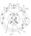
- Figure 2 shows the assembly according to the invention with a view from the pump side.
- the arrangement of the suction connection can be seen in particular in this illustration 18 and the pressure connection 17 on the lid 4c, and the suction opening 20 and the pressure opening 22 of the pump unit 10.
Landscapes
- Engineering & Computer Science (AREA)
- Power Engineering (AREA)
- Chemical & Material Sciences (AREA)
- Combustion & Propulsion (AREA)
- Mechanical Engineering (AREA)
- General Engineering & Computer Science (AREA)
- Connection Of Motors, Electrical Generators, Mechanical Devices, And The Like (AREA)
- Details Of Reciprocating Pumps (AREA)
- Motor Or Generator Cooling System (AREA)
Applications Claiming Priority (2)
| Application Number | Priority Date | Filing Date | Title |
|---|---|---|---|
| DE19721527 | 1997-05-22 | ||
| DE19721527A DE19721527C1 (de) | 1997-05-22 | 1997-05-22 | Baueinheit aus Verbrennungsmotor, Generator und Pumpenaggregat |
Publications (2)
| Publication Number | Publication Date |
|---|---|
| EP0880217A2 true EP0880217A2 (fr) | 1998-11-25 |
| EP0880217A3 EP0880217A3 (fr) | 2000-08-16 |
Family
ID=7830238
Family Applications (1)
| Application Number | Title | Priority Date | Filing Date |
|---|---|---|---|
| EP98109038A Withdrawn EP0880217A3 (fr) | 1997-05-22 | 1998-05-18 | Ensemble moteur à combustion interne, génératrice électrique et unité de pompage |
Country Status (4)
| Country | Link |
|---|---|
| EP (1) | EP0880217A3 (fr) |
| JP (1) | JPH10336967A (fr) |
| KR (1) | KR19980087205A (fr) |
| DE (1) | DE19721527C1 (fr) |
Cited By (1)
| Publication number | Priority date | Publication date | Assignee | Title |
|---|---|---|---|---|
| GB2391398A (en) * | 2002-03-01 | 2004-02-04 | Visteon Global Tech Inc | Flow path for a liquid cooled alternator |
Families Citing this family (4)
| Publication number | Priority date | Publication date | Assignee | Title |
|---|---|---|---|---|
| DE10010248A1 (de) * | 2000-03-02 | 2001-09-13 | Hatz Motoren | Stromerzeuger als Einheit aus Antriebsmotor und Generator |
| JP5206457B2 (ja) * | 2009-02-03 | 2013-06-12 | コベルコ建機株式会社 | ハイブリッド作業機械の軸潤滑装置 |
| KR101504670B1 (ko) * | 2014-12-24 | 2015-03-23 | (주) 대진유압기계 | 알터네이터 및 복동 솔레노이드 밸브를 갖는 2500바 엔진유압펌프 |
| NL2019302B1 (en) * | 2017-07-20 | 2019-02-12 | E Traction Europe Bv | In-wheel electric motor provided with a cooling system |
Family Cites Families (7)
| Publication number | Priority date | Publication date | Assignee | Title |
|---|---|---|---|---|
| US4320431A (en) * | 1980-02-26 | 1982-03-16 | Westinghouse Electric Corp. | Fluid circulating pump |
| US4980588A (en) * | 1986-02-14 | 1990-12-25 | Mitsubishi Denki Kabushiki Kaisha | Water-cooled vehicle generator |
| ATE118635T1 (de) * | 1986-12-20 | 1995-03-15 | Kyodo Printing Co Ltd | Karte für optische aufzeichnung und verfahren zu ihrer herstellung. |
| US5129795A (en) * | 1991-05-31 | 1992-07-14 | Powerdyne Corporation | Motor driven pump |
| DE4404791C1 (de) * | 1994-02-08 | 1995-03-30 | Mannesmann Ag | Baueinheit aus einem Verbrennungsmotor und einem elektrischen Generator |
| JPH0988807A (ja) * | 1995-09-28 | 1997-03-31 | Yuken Kogyo Co Ltd | モータ一体型油圧ポンプ装置 |
| FR2742606B1 (fr) * | 1995-12-18 | 1998-01-16 | Renault | Machine electrodynamique, notamment alternateur de vehicule automobile refroidi par eau |
-
1997
- 1997-05-22 DE DE19721527A patent/DE19721527C1/de not_active Expired - Fee Related
-
1998
- 1998-05-18 EP EP98109038A patent/EP0880217A3/fr not_active Withdrawn
- 1998-05-20 KR KR1019980018088A patent/KR19980087205A/ko not_active Withdrawn
- 1998-05-22 JP JP10140681A patent/JPH10336967A/ja active Pending
Cited By (2)
| Publication number | Priority date | Publication date | Assignee | Title |
|---|---|---|---|---|
| GB2391398A (en) * | 2002-03-01 | 2004-02-04 | Visteon Global Tech Inc | Flow path for a liquid cooled alternator |
| GB2391398B (en) * | 2002-03-01 | 2004-09-01 | Visteon Global Tech Inc | Liquid cooled alternator |
Also Published As
| Publication number | Publication date |
|---|---|
| DE19721527C1 (de) | 1998-11-05 |
| KR19980087205A (ko) | 1998-12-05 |
| EP0880217A3 (fr) | 2000-08-16 |
| JPH10336967A (ja) | 1998-12-18 |
Similar Documents
| Publication | Publication Date | Title |
|---|---|---|
| AT503361B1 (de) | Antrieb | |
| DE4415031C1 (de) | Hydrodynamische Einrichtung als Heizgenerator für ein Kraftfahrzeug | |
| EP2153507B1 (fr) | Groupe électrogène composé d'un moteur à combustion interne et d'un générateur | |
| DE102007033457A1 (de) | Elektrische Maschine mit einem flüssigkeitsgekühlten Rotor | |
| EP0778649A1 (fr) | Ensemble moto-pompe | |
| DE102012202460A1 (de) | Elektromotorische Getriebevorrichtung mit einstückigem Gehäuse | |
| EP0593913A2 (fr) | Pompe hydraulique entraînée par moteur électrique | |
| DE102019217872A1 (de) | Modularer elektrischer Achsantrieb | |
| DE2951961A1 (de) | Getriebeabdeckung | |
| EP1395454A1 (fr) | Systeme d'entrainement hybride a convertisseur de couple | |
| DE19628576A1 (de) | Antrieb für ein Förderrad einer Fördereinrichtung eines Kraftfahrzeugs | |
| DE112022007787T5 (de) | Gehäuseanordnung und Elektroantrieb mit einer solchen Gehäuseanordnung | |
| EP1574714B1 (fr) | Unité de pompage | |
| DE102008034175A1 (de) | Elektrohydraulische Antriebsanordnung | |
| EP0722867B1 (fr) | Unité d'entraínement avec un moteur à combustion interne et un ralentisseur hydrodynamique. | |
| DE112006003223T5 (de) | Elektrische Maschine mit flüssigkeitsgekühltem Rotor | |
| EP0711692A1 (fr) | Unité d'entraînement avec un moteur à combustion interne et un ralentisseur hydrodynamique | |
| EP0913598A1 (fr) | Connexion pour convertisseur de couple hydrodynamique avec amortisseur de vibrations | |
| DE19721527C1 (de) | Baueinheit aus Verbrennungsmotor, Generator und Pumpenaggregat | |
| EP1081003B1 (fr) | Ensemble pour moteur à combustion interne | |
| DE3702028A1 (de) | Verbrennungsmotor mit wasserkuehlung | |
| DE10203259A1 (de) | Antrieb für ein Kraftfahrzeug | |
| EP0711690A2 (fr) | Unité d'entraînement à un moteur à combustion interne et un retardateur hydrodynamique | |
| DE3409605A1 (de) | Mit der schmierstoffpumpe gemeinsam angetriebene kuehlfluessigkeitspumpe | |
| DE19750379A1 (de) | Baueinheit mit einem elektrischen Generator und einem Pumpenaggregat |
Legal Events
| Date | Code | Title | Description |
|---|---|---|---|
| PUAI | Public reference made under article 153(3) epc to a published international application that has entered the european phase |
Free format text: ORIGINAL CODE: 0009012 |
|
| AK | Designated contracting states |
Kind code of ref document: A2 Designated state(s): DE FR GB IT |
|
| AX | Request for extension of the european patent |
Free format text: AL;LT;LV;MK;RO;SI |
|
| PUAL | Search report despatched |
Free format text: ORIGINAL CODE: 0009013 |
|
| AK | Designated contracting states |
Kind code of ref document: A3 Designated state(s): AT BE CH CY DE DK ES FI FR GB GR IE IT LI LU MC NL PT SE |
|
| AX | Request for extension of the european patent |
Free format text: AL;LT;LV;MK;RO;SI |
|
| RIC1 | Information provided on ipc code assigned before grant |
Free format text: 7H 02K 7/18 A, 7H 02K 9/19 B, 7H 02K 7/00 B, 7F 04B 17/05 B |
|
| 17P | Request for examination filed |
Effective date: 20000926 |
|
| AKX | Designation fees paid |
Free format text: DE FR GB IT |
|
| STAA | Information on the status of an ep patent application or granted ep patent |
Free format text: STATUS: THE APPLICATION IS DEEMED TO BE WITHDRAWN |
|
| 18D | Application deemed to be withdrawn |
Effective date: 20011201 |