EP0880294A2 - Appareil de réception et procédé d'étabilissement d'un canal de réception - Google Patents
Appareil de réception et procédé d'étabilissement d'un canal de réception Download PDFInfo
- Publication number
- EP0880294A2 EP0880294A2 EP98109232A EP98109232A EP0880294A2 EP 0880294 A2 EP0880294 A2 EP 0880294A2 EP 98109232 A EP98109232 A EP 98109232A EP 98109232 A EP98109232 A EP 98109232A EP 0880294 A2 EP0880294 A2 EP 0880294A2
- Authority
- EP
- European Patent Office
- Prior art keywords
- channel
- channel information
- detected
- information
- signal
- Prior art date
- Legal status (The legal status is an assumption and is not a legal conclusion. Google has not performed a legal analysis and makes no representation as to the accuracy of the status listed.)
- Withdrawn
Links
Images


Classifications
-
- H—ELECTRICITY
- H04—ELECTRIC COMMUNICATION TECHNIQUE
- H04W—WIRELESS COMMUNICATION NETWORKS
- H04W48/00—Access restriction; Network selection; Access point selection
- H04W48/16—Discovering, processing access restriction or access information
-
- H—ELECTRICITY
- H04—ELECTRIC COMMUNICATION TECHNIQUE
- H04B—TRANSMISSION
- H04B17/00—Monitoring; Testing
- H04B17/30—Monitoring; Testing of propagation channels
- H04B17/309—Measuring or estimating channel quality parameters
- H04B17/318—Received signal strength
-
- H—ELECTRICITY
- H04—ELECTRIC COMMUNICATION TECHNIQUE
- H04W—WIRELESS COMMUNICATION NETWORKS
- H04W88/00—Devices specially adapted for wireless communication networks, e.g. terminals, base stations or access point devices
- H04W88/02—Terminal devices
- H04W88/022—Selective call receivers
Definitions
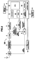
- FIG. 2 shows the circuit arrangement of the above-mentioned paging receiver 100.
- the radio signal for calling this paging receiver 100 conforms to the high-grade radio paging system and is received by an antenna 1 and sent to an RF unit 2.
- the radio frequency signal received by the antenna 1 is suitably amplified in accordance with an AGC signal (to be described later) and sent out to a frequency conversion unit 3.
- the CPU 63 controls the operation of this receiver as a whole.
- the CPU 63 transmits a switching signal to the switch 9, makes the PLL synthesizer 10 output the local oscillation frequency signal, and makes the information received by this receiver, the area information at the time of roaming process (to be described later), etc. be displayed in a display unit 11, and further, receives the signal from a key input unit 12 which sets the received channel frequency when the user moves across service areas.
- the A/D conversion unit 8 digitalizes, in accordance with a predetermined sampling frequency and a predetermined quantization bit number, the RSSI signal sent from the signal intensity detection unit 7 and transmits it to the CPU 63 in the control unit 6.
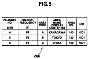
- the channel memory CHM is configured as shown in FIG. 5 and stores the channel No. and the channel frequencies in which the NID to be transmitted in the respective areas which are able to receive a multi-roaming service is set, an area code, an area name (display contents), the area No. which is used when area registration is performed, and the address of the NID in a state associating them with one another.
- FIG. 5 shows the state in which the channel Nos. "4" to "6", the channel frequencies "F4" to "F6", the area codes "A" to "C” , the area names "Kanagawa", “Tokyo” and “Chiba", the area Nos. "140", “130” and “120” and the NID address "NID1".
- the address of the NID has the common contents for the same paging service company.
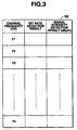
- the first channel frequency F1 set in the receiving state setting area of the RAM 62 shown in FIG. 3 is set (step A1), and, in the ordinary receiving state with the switch 9 turned on, reception of the signal is established at the set frequency.
- a bit rate signal with a fixed pulse width is detected, and the result as to whether the signal has been detected or not is stored in the corresponding channel frequency area of the receiving state setting area of the RAM 62 (step A2).
- step A3 In the state in which the switch 9 is turned off to cut off the supply of the RSSI signal as the AGC signal to the RE unit (step A3), a signal of the channel frequency is received.
- the RSSI signal obtained from the signal intensity detection unit 7 at this time is digitalized by the A/D conversion unit 8 and stored, as information representative of the signal intensity at the channel, in the corresponding channel frequency area portion of the receiving state setting area of the RAM 62 (step A4).
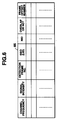
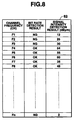
- FIG. 8 shows the contents of the receiving state setting area of the RAM 62 in this state. Thereafter, if, at step A6, it is determined that the scan of all the frequency channels has been completed, then the process of setting the channel frequency of which the bit rate detected is "OK" and the detected signal intensity is high, and at which a stable reception can be expected, is executed with reference to the receiving state setting area (step A8). Then, the processes shown in FIG. 7 are terminated.
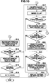
- FIG. 9 and FIG. 10 show a series of operations relating to the process of setting the channel frequency with reference to the receiving state setting area.
- steps B1 and B2 show those channel frequencies of which the bit rate detection results are "OK" are extracted (step B1).
- the channel frequencies of which the signal intensity detection results are 50 [dB ⁇ m] or higher are selected, and the channel frequencies and the signal intensities are transferred to the list memory 65 (step B2).
- the channel frequency in which the desired NID is received earliest can be detected among the searched frequencies based on the current time and the searched frequencies. If the searched frequencies contain a channel frequency having a frame offset, it is necessary to amend the frequency based on a time corresponding to the offset before detecting the channel frequency.
- step B6 After the synchronizing signal portion consisting of the first synchronizing portion S1, the frame information FI, and the second synchronizing portion S2 is searched for again (step B6), it is determined whether or not the synchronizing signal portion has been detected (step B7). If it is determined that the synchronizing signal portion has been detected, then it is determined whether or not "1" is set as the roaming network bit RNB in the frame information FI in the detected synchronizing signal portion (step B8).
- step B9 If it is determined that "1" is set as the roaming network bit RNB, then it is determined that, the multi-area roaming service is executed at this channel frequency, and it is further determined whether or not the transmitted frame is the NID transmitting frame based on the frame No. data (step B9). If it is determined that the transmitted frame is the NID transmitting frame, it is determined whether or not the NID could actually be detected from the address field AF (step B10).
- the area name corresponding to the channel are read out from the channel memory CHM and displayed in the display unit 11 (step B14).
- FIG. 12 shows the state of display in the display unit 11.
- a signal is received in a very good receiving state at the channel frequency F4 (ch4); it is displayed that the channel frequency is that from the exchange at "Kanagawa" of the area No. "140".
- step B15 depending on whether or not a decision instruction is made by a key manipulation in the key input unit 12 in the state in which, in response to the message "Do you want to register?" displayed, "Y (YES)" put therebelow is displayed with an underline in FIG. 12, it is determined whether or not the decision of the channel has been detected (step B15). If it is determined that the decision has been detected, then the receiving channel is set so as to receive the signal at the channel frequency (step B16), with which the processes shown in FIG. 9 and FIG. 10 are terminated. While, on the other hand, the user transmits to the exchange station in this service area the service code of the multi-area roaming service, the password No. previously set through the exchange in the service area, and the area No. are transmitted from the nearest telephone terminal, thus completing the registration.
- step B8 If, at the above-mentioned step B8, it is determined that the roaming network bit RNB "1" is not set in the frame information FI, it is determined that the multi-area roaming service is not being executed at this channel frequency.
- step B17 the data of the corresponding channel frequency is deleted from the list memory 65.
- step B7 If it is determined, at step B7, that no synchronizing signal portion could be detected and if it is determined, at step B9, that the frame is not the NID transmitting frame, the flow returns to step 6, to carry out the processes starting from the process of searching for the synchronizing signal portion at the channel frequency, again.
- step B10 It is determined, at step B10, that the NID could not be detected from the address field AF though the received frame is the NID transmitting frame, it is confirmed that it is less than three times that the phenomenon that "the NID could not be detected though the frame received at the channel frequency is the NID transmitting frame" has occurred (step B11). Thereafter, the flow returns to step B6 for retry, thus carrying out the processes starting from the process of searching for the synchronizing signal portion again.
- step B11 If it is determined, at step B11, that the phenomenon that "the NID could not be detected though the frame received at the channel frequency is the NID transmitting frame" has occurred for the third time, then it is judged that the NID is not transmitted at the channel frequency, and the data of the channel frequency is deleted from the list memory 65 (step B17).
- step B13 If it is determined, at step B13, that the NID is not registered in the channel memory CHM of the ID-ROM 64 or if, in response to the displayed massage "Do you want to register?", "N (NO)" given therebeneath is instructed, and thus, it is determined, at step B15, that the receiving channel has not been determined, the data of the channel frequency is likewise deleted from the list memory 65 at step B17.
- search is made for those channel frequencies of which the NID can be detected in accordance with the list memory 65. If there is one, then the channel frequency is displayed in the display unit 11, and a decision instruction is detected. When the decision is detected, the receiving channel is set under the assumption that a signal is received at the channel frequency.
- the candidates for the channel frequency corresponding are successively deleted from the list memory 65. If it is determined that any other channel frequency does not remain in the list memory 65, the hitherto used condition that "the signal intensity detection result is 30 [dB ⁇ m] or higher” is lowered to the lower-level condition that "the signal intensity detection result is lower than 30 [dB ⁇ m]. Thereafter, from the receiving state setting area of the RAM 62, it is determined whether or not there is a channel frequency of which the bit rate detection result is "OK" and the signal intensity detection result is lower than 30 [dB ⁇ m] (step B23).
- the channel frequency of which the bit rate detection result is "OK" is selected from the channel frequencies, and the channel frequency and the signal intensity thereof are transferred to the list memory 65 (step B24). Then, the flow returns to step B3 again, and thus, signal reception is continued at the respective transferred frequencies until the synchronizing signal portion can be detected.
- the frame No. data stored in each frame information FI are read out, and the frame No. data are stored and set in the corresponding channel frequency area of the list memory 65.
- those channel frequencies of which the NID is detectable are searched for in accordance with the contents of the list memory 65, so that, if there is one, then it is displayed in the display unit 11 and then the decision instruction is detected.
- the receiving channel is set under the assumption that a signal can be received at the channel frequency.
- the candidates for the channel frequency are deleted from the list memory 65; and, if it is determined at step B19 that no other channel frequency exists any more in the list memory 65, then the flow proceeds to step B23 through step B21. In this case, since any channel frequency of which, in the lower-level conditions, the bit rate detection result which is "OK" does not exist in the receiving state setting area of the RAM 62, the user cannot receive the paging service at the channel frequencies of any signal intensity.
- this paging receiver 100 is out of any service area, and a message to the effect that this paging receiver is outside the range of service areas is displayed on the display unit 11 (step B25). Then the processes shown in FIG. 9 and FIG. 10 are terminated.
- the signal intensities at the respective channel frequencies are scanned beforehand, and it is determined step-wise whether or not a signal can be surely received at the channel frequency ranging from the channel frequency having the highest signal intensity to the channel frequencies having lower signal intensities. Therefore, the length of time required for the receiving roaming process which has been one minute or longer in the conventional process can be substantially shortened to about 18 seconds, and in turn, the feeling of uneasiness at the user is eliminated, and the period of time during which the user can receive no paging service can be shortened as much as possible; and even when the user moves from one service area to another, it is possible to quickly shift into a state ready for receiving the paging service.
- bit rate detection and the signal intensity detection are performed with respect to all the 36 channels at the time of the roaming process, but it is possible to alter the embodiment in which the signal intensity detection is performed with respect to only those of the 36 channels of which the bit rate detection is "OK".
- the paging receiver 100 is in the same state as in the case shown in FIG. 1, and, as for the constitution of the paging receiver 100, it is the same as that shown in FIGS. 2 to 6, so that the same component portions are referenced by the same reference numerals, whereby the repetition of the description thereof is omitted.
- FIG. 13 shows the roaming process according to the second embodiment.
- the first channel frequency F1 which is set in the receiving state setting area of the RAM 62 is set (step A11).
- the synchronization at the set channel frequency is executed, a bit rate signal with a fixed pulse width is detected, and the detection result is stored in the part, corresponding to the particular channel frequency, of the receiving state setting area of the RAM 62 (step A12).
- the switch 9 is turned off to cut off the supply of the RSSI signal as AGC signal to the RF unit 2 (step A14).
- a signal is received at the same channel frequency, in which the RSSI signal obtained from the signal intensity detection unit 7 is digitalized by the A/D conversion unit 8 and stored in the part, corresponding to the channel frequency, of the receiving state setting area of the RAM 62 as information representative of the signal intensity of the channel frequency (step A15).
- step A16 the switch 9 is again turned on to supply the RSSI signal as AGC signal to the RF unit 2 (step A16). After it is confirmed that other channel frequencies to be scanned are left (step A17), the next channel frequency is newly set (step A18), and then, the flow returns to the process at step A12.
- step A13 If it is determined at step A13 that the detected bit rate signal is not the value desired by the receiver 100, the flow proceeds to step A18, omitting processes at steps A14 to A17.
- steps A12 to A18 are thus repeatedly executed, and the values of the detected bit rate signals and the detected signal intensities with reference to all the channel frequencies are stored in the receiving state setting area of the RAM 62. Thereafter, if it is determined, at step A17, that the scan of all the channel frequencies has been completed, then the process of setting the channel frequency at which the signal intensity is high and stable reception can be performed at the desired bit rate is executed (step A19). Then, the process shown in FIG. 13 is completed.
- the channel frequency setting process is the same as that described in connection with FIGS. 9 and 10, and therefore, the description thereof is omitted.
- the second embodiment may be modified in which the roaming process is executed in such a manner that, after the detection of the signal intensities at all the 36 channel frequencies is executed, only those channel frequencies of which the signals can be surely received, that is, the signal intensities thereof are higher than a predetermined value are selected to perform the bit rate detection thereof.
- a third embodiment in which the present invention is applied to a paging receiver 100 utilizing the paging service based on a high-grade radio paging system will be described.
- FIG. 14 shows a service area B in which the paging receiver 100 is located at present and the service areas A, C, D and E which are located adjacent to the service area B and in which the same NID which can reach the paging receiver 100, that is, the NID1 is transmitted, wherein the channel frequencies at which the NID and LID are transmitted are also shown.
- the channel frequencies at which the NID and LID are transmitted are also shown.
- the channel frequencies at which the NID1 is transmitted are F4
- the channel frequencies at which the LID1 is transmitted are F1 and F4
- the channel frequencies at which the LID1 is transmitted are F1 and F4
- the channel frequencies at which the LID1 is transmitted are F5 and the channel frequencies at which the LID3 is transmitted are F2 and F5.
- the paging receiver 100 performs the process for setting the channel frequency of a service area, of the areas shown, where signal reception is possible.
- FIG. 15 shows a table stored in the channel memory CHM of the ID-ROM 64, which is used when the user receives the multi-roaming service using the NID and LID.
- the NID the respective service areas are designated, and by the LID, the respective service areas are divided into smaller portions.
- the channel No., the channel frequency, the local channel ID (LID), the network ID (NID), the area code, the area name (the display contents), and area No. used at the time of making an area registration are stored in a manner associating them with one another.
- the user of the paging receiver 100 can receive the services of ten divided service areas by setting channel frequencies F1 - F8 in five service areas "A" - "E".
- FIG. 16 shows the results relating to the absence or presence of the bit rate detection and the signal intensities which are stored in the receiving state setting area of the RAM 62, with reference to all the channels such as, 36 channels.
- the process of setting the channel frequency which can assure a stable reception is executed in accordance with the bit rate detection result and the magnitudes of the signal intensities detected with reference to the receiving state setting area of the RAM 62.
- those channel frequencies of which the bit rate detection results are "OK" are extracted from the receiving state setting area of the RAM 62 (step B1).
- those of which the signal intensity detection results are higher than 50 [dB ⁇ m] are selected, and these channel frequencies and the signal intensities are transferred to the list memory 65 (step B2).
- a signal is continuously received until the synchronizing signal portion consisting of the first synchronizing portion S1, the frame information FI and the second synchronizing portion S2 can be detected; and the frame No. data stored in this frame information FI is read out (step B3).
- the frame No. data thus read out is stored and set in the list memory 65 (step B4).
- FIG. 17 shows the contents set in the list memory 65 in this case.
- the channel frequency - such as, the channel frequency "F6" of the frame No. data 7 - of which the arrival timing of the NID transmitted in every 8 frames such as, frame Nos. "0", “8", “16", “32”, ..., "120" seems to be nearest, is set (step B5).
- the block information BI in this frame is read in (step B31).
- the SSID1 set in the second to the fourth code words is read in (step B32).
- the LID is extracted therefrom (step B33).
- step B36 If it is determined that the NID could be detected, then the thus detected NID is read in (step B36). Thereafter, the information relating to the NID, that is, the absence or presence of the overlap of the NID on the SSID1 and SSID2 including the LID extracted, and the frame offset number are stored, together with the NID thus detected, in the corresponding channel frequency section of the list memory 65 (step B37). Thereafter, it is determined whether or not the NID and the LID are respectively registered in the channel memory CHM of the ID-ROM 64 shown in FIG. 15 (step B38).
- the display contents corresponding to the NID and LID are read out from the channel memory CHM and displayed in the display unit 11 (step B39).
- FIG. 20 shows the state in which, after it is determined, at step B35, that the NID1 could be detected as the NID, the thus detected NID1 is read in at step B36, and further, at step B37, the information relating to the NID1, that is, the information relating to the absence or presence of any overlap of the NID1 on the SSID1 and SSID2 including the LID4 already detected and the frame offset number "0" are stored, together with the detected NID1, in the corresponding channel frequency section of the list memory 65.
- step B38 it is determined, at step B38, that the NID1 and LID4 are both registered in the channel memory CHM of the ID-ROM 64 shown in FIG. 15, and, at step B39, the display contents corresponding to the NID1 and the LID4 are read out from the channel memory CHM and displayed in the display unit 11.
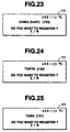
- FIG. 23 shows the displayed state of the display unit 11 in this case, wherein a signal is received at the channel frequency F6 (ch6) in a very good receiving state, and the channel frequency is supplied from the exchange at "Chiba (Eastern Area)" of the area No. "120".
- step B40 it is determined whether or not the decision of the channel was detected. If it is determined that the decision was detected, the receiving channel is set under the assumption that a signal is received at this channel frequency (step B16). The processes shown in FIG. 18 and FIG. 19 are completed, while on the other hand, the user transmits through the nearest telephone set the service code of the multi-area roaming service, the password number previously determined through the exchange in this service area, and the area No. to the exchange in the service area, whereby the registration of the service area is completed.
- step B34 If it is determined, at step B34, that the corresponding frame is not the NID transmitting frame, the flow returns to step B6, performing the process starting from the search for the synchronizing signal portion at the channel frequency again.
- step B35 If it is determined, at step B35, that the NID could not be detected from the address field AF though the received frame is the NID transmitting frame, it is confirmed that the phenomenon that "the NID could not be detected though the frame received at the channel frequency is the NID transmitting frame" has not yet been repeatedly caused three times including the preceding similar process (step B41). Thereafter, the flow returns to step B6 for retry, whereby the operation starting from the search for the synchronizing signal portion at the channel frequency is carried out again.
- the information other than the NID that is, the absence or presence of overlap thereof on the SSID1 and SSID2 including the LID, and the frame offset number are stored in the corresponding channel frequency section of the list memory 65 (step B42). Thereafter, the flow proceeds to step B18 as in the case where it is determined, at step B38, that the corresponding NID and LID are not registered together in the channel memory CHM of the ID-ROM 64.
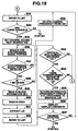
- step B47 it is determined whether or not the synchronizing signal portion could be detected. If it is determined that the synchronizing signal portion could be detected, then it is determined whether or not "1" is set as the roaming network bit RNB in the frame information FI in the detected synchronizing signal portion (step B48).
- the multi-area roaming service is not executed at the channel frequency if "1" is not set as the roaming network bit RNB.
- the data on the channel frequency is deleted from the list memory 65 at step B58. If the synchronizing signal portion is not detected, the signal reception at the channel frequency is continued until the synchronizing signal portion is detected. If the synchronizing signal portion is detected, and if it is determined that "1" is set as the roaming network bit RNB of the frame information FI of the synchronizing signal portion, then the block information BI of the frame is read in (step B49). The SSID1 set in the block information BI thus read in is read in (step B50), and the LID is extracted therefrom (step B51).
- the LID extracted in the reception at the channel frequency "F5" is "LID3", so that, with the thus extracted "LID3", the list memory 65 is referred to (step B52), and it is determined whether or not there is a channel frequency having the LID identical with the extracted LID (step B53).
- the LID stored in the list memory 65 is only the "LID4" of the channel frequency "F6" as shown in FIG. 20 and therefore it is determined that the LID is not identical with the "LID3", and the flow returns to step B34 again.
- step B34 determines whether or not the NID could be detected from the address field AF. If it is determined that the NID could be detected, then the detected NID, that is, the "NID1" is read in at step B36. At step B37, the information relating to the NID, that is, the absence or presence of an overlap thereof on the SSID1 and SSID2 including the LID, and the frame offset number are stored, together with the detected NID, in the corresponding channel frequency "F5" section of the list memory 65.
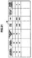
- FIG. 21 shows the state in which the information relating to the NID1 obtained at the channel frequency "F5" at step B37, that is, the respective information on the absence of any overlap thereof on the SSID1 and SSID2 containing the LID3, and the frame offset number "0" are stored, together with the NID1 detected, in the section of the corresponding channel frequency F5 section of the list memory 65.
- step B38 it is determined that the NID1 and LID3 are both registered in the channel memory CHM of the ID-ROM 64 shown in FIG. 15, and, at step B39, the display contents corresponding to the NID1 and LID3 are read out from the channel memory CHM and displayed in the display unit 11.
- FIG. 24 shows the state displayed in the display unit 11 in this case, wherein it is shown that the reception at the channel frequency F5 (ch5) is established in a very good receiving state; and the channel frequency is supplied from the exchange at "Tokyo" of the area No. "130".
- step B40 Depending on whether or not a decision instruction is made by a key manipulation in the key input unit 12 at step B40 in the state in which, as shown, in response to the massage "Do you want to register?", the "Y (YES)" given therebeneath is cursor-indicated as shown by an underline, it is determined whether or not the decision of the channel was detected. If it is determined that the decision was detected, the receiving channel is set under the assumption that a signal can be received at the channel frequency (step B16). The processes shown in FIG. 18 and FIG. 19 are terminated, while on the other hand, the user transmits by the nearest telephone set to the exchange in the service area corresponding the service code of the multi-area roaming service, the password number previously determined through the exchange in the service area, and the area No.
- step 40 If, at step 40, "N (NO)" is instructed in response to the display on the display unit 11, and it is determined that the cancellation of the decision on the receiving channel was detected, it is determined, by referring to the list memory 65, whether or not there are any other channel frequencies which are not received yet (steps B43 and B44). If there are some, the channel frequency of the channel frequencies of which the arrival timing of the NID seems to be nearest, such as, the channel frequency "F2" of the frame No. data "10" is set at step B45. Thereafter, signal reception is started, at step B46, at the channel frequency, and search is made for the synchronizing signal portion consisting of the first synchronizing portion S1, the frame information FI, and the second synchronizing portion S2 again.
- step B47 it is determined whether or not the synchronizing signal portion could be detected; and if it is determined that the synchronizing signal portion could be detected, then it is determined, at step B48, whether or not "1" is set as the roaming network bit RNB in the frame information FI in the synchronizing signal portion detected.
- step B58 the data of the channel frequency is deleted form the list memory 65. If the synchronizing signal portion is not detected, the signal reception at the channel frequency is continued until the synchronizing signal portion is detected. If the synchronizing signal portion is detected, and it is determined that "1" is set in the roaming network bit RNB of the frame information F1 of this synchronizing signal portion, then the flow proceeds to step B49.
- step B48 the block information BI in the frame is read in, and at succeeding step B50, the SSID1 set in the block information BI read in is read in.
- step B51 the LID is extracted therefrom.
- the LID extracted at the reception of the channel frequency "F2" is the "LID3"
- the list memory 65 with the thus extracted "LID3” to decide whether or not there are channel frequencies having the LID identical with this extracted LID (step B53).
- the LID stored in the list memory 65 is the "LID3" of the channel frequency "F5" and the "LID4" of the channel frequency "F6”, so that it is determined that there are identical ones. Then, it is determined whether or not the NID is stored corresponding to the channel frequency "F5" having the same "LID3" (step B54).
- the "NID1" is stored corresponding to the channel frequency "F5", so that decision is made on this.
- the information concerning the "LID3" which has already determined to be identical is stored, together with other information excepting the NID, that is, the absence or presence of an overlap and the frame offset information, in the section of the channel frequency "F2" under reception at present, of the list memory 65 (step B55).
- the display contents corresponding to the "No NID” and "LID3" are read out and displayed in the display unit 11.
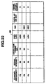
- FIG. 22 shows the information concerning the LID3 obtained at the channel frequency "F2" at step B55, that is, the respective information relating to the absence or presence of an overlap thereof on the SSID1 and SSID2 containing the LID3 and the frame offset number "0" are stored together with the information of "No NID" in the corresponding channel frequency F2 section of the list memory 65.
- step B56 the display contents corresponding to the "No NID" and the "LID3" are read out from the channel memory CHM and displayed in the display unit 11.
- FIG. 25 shows the display contents of the display unit 11 at this case; here, it is shown that the signal can be received in every good receiving state at the channel frequency F2 (ch2), and the channel frequency is supplied from the exchange at "Tama" in the area No. "131".
- step B57 it is determined whether or not the decision on the receiving channel has been detected. It is determined that the decision has been detected, the flow proceeds to step B16 to set the receiving channel under the assumption that the signal is received at the channel frequency.
- the processes shown in FIG. 18 and FIG. 19 are completed, while, on the other hand, the user transmits by the nearest telephone set the service code of the multi-area roaming service, the password number previously determined through the exchange in the service area corresponding, and the area No. to the exchange in the service area, whereby the service area registration is completed.
- step B57 If, at step B57, the "N(NO)" is instructed in response to the display in the display unit 11, and it is determined that the cancellation of the decision on the receiving channel has been detected, the flow returns to step B43, where the list memory 65 is referred to, and then, at step B44, it is determined whether or not there are any other channel frequencies which are not received.
- step B45 the flow proceeds to the process at step B45 again, or if there is none, the operation proceeds to step B21 and the following steps in order to lower the condition level for the candidates to be registered in the list memory 65.
- the channel frequency without the necessity of waiting for the reception of the NID transmitting frame, only by discriminating between the coincidence or non-coincidence of the LID; and therefore, the length of time required for the roaming process which was about 18 seconds for instance in the above-mentioned first embodiment, can be more substantially reduced to about 2 seconds; and, in turn, the feeling of uneasiness of the user is eliminated, and the length of time during which the user can receive no paging service can be reduced to an almost negligible value, whereby, even while the user is moving through service areas, the receiver can quickly shift into a state ready for the reception of the paging service.
- the speed at which the change of the receiving channel and the registration process are performed when the user is moving across service areas can be enhanced to eliminate the feeling of uneasiness of the user and to reduce as much as possible the length of time during which the user can receive no paging service.
Landscapes
- Engineering & Computer Science (AREA)
- Computer Networks & Wireless Communication (AREA)
- Signal Processing (AREA)
- Computer Security & Cryptography (AREA)
- Quality & Reliability (AREA)
- Physics & Mathematics (AREA)
- Electromagnetism (AREA)
- Mobile Radio Communication Systems (AREA)
- Channel Selection Circuits, Automatic Tuning Circuits (AREA)
Applications Claiming Priority (6)
| Application Number | Priority Date | Filing Date | Title |
|---|---|---|---|
| JP13238497 | 1997-05-22 | ||
| JP13238497 | 1997-05-22 | ||
| JP132384/97 | 1997-05-22 | ||
| JP15487097 | 1997-06-12 | ||
| JP15487097 | 1997-06-12 | ||
| JP154870/97 | 1997-06-12 |
Publications (2)
| Publication Number | Publication Date |
|---|---|
| EP0880294A2 true EP0880294A2 (fr) | 1998-11-25 |
| EP0880294A3 EP0880294A3 (fr) | 2000-03-15 |
Family
ID=26466968
Family Applications (1)
| Application Number | Title | Priority Date | Filing Date |
|---|---|---|---|
| EP98109232A Withdrawn EP0880294A3 (fr) | 1997-05-22 | 1998-05-20 | Appareil de réception et procédé d'étabilissement d'un canal de réception |
Country Status (5)
| Country | Link |
|---|---|
| US (1) | US6332078B1 (fr) |
| EP (1) | EP0880294A3 (fr) |
| KR (1) | KR19980087303A (fr) |
| CN (1) | CN1143561C (fr) |
| ID (1) | ID20325A (fr) |
Cited By (3)
| Publication number | Priority date | Publication date | Assignee | Title |
|---|---|---|---|---|
| EP1085776A3 (fr) * | 1999-09-14 | 2003-02-05 | Nec Corporation | Equipement terminal de communication mobile, son procédé de commande et support d'enregistrement pour enregistrer son programme de contrôle |
| KR100621955B1 (ko) | 2003-07-31 | 2006-09-13 | 가부시키가이샤 엔.티.티.도코모 | 무선 제어 장치 및 이동 통신 방법 |
| CN101389141B (zh) * | 2007-09-13 | 2012-02-22 | 三星电子株式会社 | 移动终端及其系统扫描方法 |
Families Citing this family (7)
| Publication number | Priority date | Publication date | Assignee | Title |
|---|---|---|---|---|
| KR20000009183A (ko) * | 1998-07-22 | 2000-02-15 | 이가형 | 중첩지역에서 호출기의 채널 선택방법 및 그호출기 |
| FI111505B (fi) * | 1999-05-31 | 2003-07-31 | Nokia Corp | Menetelmä ohjaustiedon välittämiseksi tiedonsiirtojärjestelmässä, tiedonsiirtojärjestelmä, langaton päätelaite ja tukiasemajärjestelmä |
| CN1159878C (zh) * | 2000-12-07 | 2004-07-28 | 华为技术有限公司 | 码分多址系统中基于宏分集的直接重试方法 |
| JP5141344B2 (ja) * | 2007-05-31 | 2013-02-13 | ソニー株式会社 | 受信装置、プログラム、および受信方法 |
| US9706479B2 (en) * | 2009-08-02 | 2017-07-11 | Intel Deutschland Gmbh | Frequency retention and reuse |
| EP2826306A1 (fr) * | 2012-03-16 | 2015-01-21 | Sony Mobile Communications AB | Recherche de canaux sur la base d'informations de disponibilité de canaux |
| CN112152738B (zh) * | 2020-09-25 | 2022-08-19 | 广州粒子微电子有限公司 | 基于NB-IoT的快速扫频方法及装置 |
Family Cites Families (13)
| Publication number | Priority date | Publication date | Assignee | Title |
|---|---|---|---|---|
| US5065423A (en) | 1985-11-27 | 1991-11-12 | At&E Corporation | Paging system with registration mode |
| KR910008738B1 (ko) | 1987-02-20 | 1991-10-19 | 닛본 덴기 가부시기가이샤 | 밧데리 절약 채널 스캔 기능을 갖고 있는 휴대용 무선 송수신기 |
| US5262769A (en) | 1990-04-23 | 1993-11-16 | Reach Electronics, Inc. | Programmed scanning pager receiver |
| US6006107A (en) * | 1991-10-16 | 1999-12-21 | Kabushiki Kaisha Toshiba | Radio telecommunication apparatus and method having stored system identification numbers |
| US5504803A (en) * | 1991-11-25 | 1996-04-02 | Matsushita Electric Industrial Co., Ltd. | Method for automatic mode selection for a dual-mode telephone handset for use in a cellular mobile telephone system and in a wireless telephone system |
| US5442806A (en) * | 1993-06-08 | 1995-08-15 | Oki Telecom | Preferred carrier selection method for selecting any available cellular carrier frequency when neither home nor preferred cellular carrier frequencies are available |
| US5537100A (en) | 1994-04-06 | 1996-07-16 | Sharp Microelectronics Technology, Inc. | System and method for analyzing coded transmission sent to mobile message receivers |
| US5610919A (en) | 1995-01-24 | 1997-03-11 | Motorola, Inc. | Network identification information placement architecture for messaging system having roaming capability |
| US5983115A (en) * | 1996-08-13 | 1999-11-09 | Lucent Technologies Inc. | Geographic based method for selecting a wireless communications service provider |
| US5995834A (en) * | 1996-12-24 | 1999-11-30 | At&T Wireless Services, Inc. | Method for controlling channel re-selection from a selected control channel to an alternative control channel |
| US5987324A (en) * | 1997-02-24 | 1999-11-16 | Nokia Mobile Phones Limited | Method to prevent cellular phone from receiving control channel of wrong system |
| US6134445A (en) * | 1997-07-24 | 2000-10-17 | Lucent Technologies, Inc. | Wireless terminal adapted for measuring signal propagation characteristics |
| US6185422B1 (en) * | 1998-06-19 | 2001-02-06 | Nokia Mobile Phones Ltd | Method and apparatus for transitioning between control channels in a cellular system |
-
1998
- 1998-05-18 US US09/080,701 patent/US6332078B1/en not_active Expired - Fee Related
- 1998-05-20 ID IDP980751A patent/ID20325A/id unknown
- 1998-05-20 EP EP98109232A patent/EP0880294A3/fr not_active Withdrawn
- 1998-05-22 CN CNB981029477A patent/CN1143561C/zh not_active Expired - Fee Related
- 1998-05-22 KR KR1019980018551A patent/KR19980087303A/ko not_active Ceased
Cited By (4)
| Publication number | Priority date | Publication date | Assignee | Title |
|---|---|---|---|---|
| EP1085776A3 (fr) * | 1999-09-14 | 2003-02-05 | Nec Corporation | Equipement terminal de communication mobile, son procédé de commande et support d'enregistrement pour enregistrer son programme de contrôle |
| US7142526B1 (en) | 1999-09-14 | 2006-11-28 | Nec Corporation | Mobile communication terminal equipment, control method therefor, and recording medium on which control program therefor is recorded |
| KR100621955B1 (ko) | 2003-07-31 | 2006-09-13 | 가부시키가이샤 엔.티.티.도코모 | 무선 제어 장치 및 이동 통신 방법 |
| CN101389141B (zh) * | 2007-09-13 | 2012-02-22 | 三星电子株式会社 | 移动终端及其系统扫描方法 |
Also Published As
| Publication number | Publication date |
|---|---|
| KR19980087303A (ko) | 1998-12-05 |
| CN1143561C (zh) | 2004-03-24 |
| CN1204218A (zh) | 1999-01-06 |
| US6332078B1 (en) | 2001-12-18 |
| EP0880294A3 (fr) | 2000-03-15 |
| ID20325A (id) | 1998-11-26 |
Similar Documents
| Publication | Publication Date | Title |
|---|---|---|
| US6185436B1 (en) | Wireless communication system | |
| US6178335B1 (en) | Wireless communication system | |
| CA2250032C (fr) | Procede et appareil de selection de systeme prefere | |
| KR920005906B1 (ko) | 무선 전화 원격 통신장치 | |
| US5463675A (en) | Extended home indentification being used by the same service provider as a home identification in a service area other than the home service area for cellular radio telephone systems | |
| US5442680A (en) | Dual system cellular cordless radiotelephone apparatus with sub-data channel timing monitor | |
| USH610H (en) | Cellular pager | |
| EP0858237A2 (fr) | Recherche intelligente de réseau pour un appareil radiotéléphonique multimode | |
| US20020193112A1 (en) | Mobile communication apparatus | |
| US5854980A (en) | Radio communication apparatus connected with a base station used in a service area prior to the others | |
| EP0880294A2 (fr) | Appareil de réception et procédé d'étabilissement d'un canal de réception | |
| AU680755B2 (en) | Power saving system for a mobile radio | |
| EP0563898B1 (fr) | Téléphone-radio portable et procédé pour changer les canaux radio a moindre frais | |
| GB2257334A (en) | Extended home system identification for cellular radiotelephone systems | |
| US7532886B2 (en) | Mobile radio communication apparatus for selecting a high priority system at the time of turning power on | |
| US20020052189A1 (en) | Mobile radio communication apparatus | |
| JP3252524B2 (ja) | 携帯電話機及び無線チャネル設定方法 | |
| JP2885648B2 (ja) | 無線端末 | |
| JPH1169415A (ja) | 受信装置及び受信チャネル設定方法 | |
| JP3457627B2 (ja) | 移動通信方法及び移動局 | |
| JPH11187451A (ja) | 複数システム間での切換可能な携帯電話システム | |
| KR100491516B1 (ko) | 우선시스템선택을수행하는방법및장치 | |
| JPH09284852A (ja) | 移動体無線機における通信回線自動選択装置 | |
| JPH0336344B2 (fr) | ||
| JPH0955970A (ja) | 無線選択呼出受信機 |
Legal Events
| Date | Code | Title | Description |
|---|---|---|---|
| PUAI | Public reference made under article 153(3) epc to a published international application that has entered the european phase |
Free format text: ORIGINAL CODE: 0009012 |
|
| 17P | Request for examination filed |
Effective date: 19980520 |
|
| AK | Designated contracting states |
Kind code of ref document: A2 Designated state(s): DE FR GB |
|
| AX | Request for extension of the european patent |
Free format text: AL;LT;LV;MK;RO;SI |
|
| PUAL | Search report despatched |
Free format text: ORIGINAL CODE: 0009013 |
|
| AK | Designated contracting states |
Kind code of ref document: A3 Designated state(s): AT BE CH CY DE DK ES FI FR GB GR IE IT LI LU MC NL PT SE |
|
| AX | Request for extension of the european patent |
Free format text: AL;LT;LV;MK;RO;SI |
|
| AKX | Designation fees paid |
Free format text: DE FR GB |
|
| 17Q | First examination report despatched |
Effective date: 20011120 |
|
| STAA | Information on the status of an ep patent application or granted ep patent |
Free format text: STATUS: THE APPLICATION IS DEEMED TO BE WITHDRAWN |
|
| 18D | Application deemed to be withdrawn |
Effective date: 20020603 |