EP0880450B1 - Systeme pour le chargement de navires en mer - Google Patents
Systeme pour le chargement de navires en mer Download PDFInfo
- Publication number
- EP0880450B1 EP0880450B1 EP96933664A EP96933664A EP0880450B1 EP 0880450 B1 EP0880450 B1 EP 0880450B1 EP 96933664 A EP96933664 A EP 96933664A EP 96933664 A EP96933664 A EP 96933664A EP 0880450 B1 EP0880450 B1 EP 0880450B1
- Authority
- EP
- European Patent Office
- Prior art keywords
- anchor
- hose
- swivel
- swivel device
- seabed
- Prior art date
- Legal status (The legal status is an assumption and is not a legal conclusion. Google has not performed a legal analysis and makes no representation as to the accuracy of the status listed.)
- Expired - Lifetime
Links
Images




Classifications
-
- B—PERFORMING OPERATIONS; TRANSPORTING
- B63—SHIPS OR OTHER WATERBORNE VESSELS; RELATED EQUIPMENT
- B63B—SHIPS OR OTHER WATERBORNE VESSELS; EQUIPMENT FOR SHIPPING
- B63B21/00—Tying-up; Shifting, towing, or pushing equipment; Anchoring
- B63B21/50—Anchoring arrangements or methods for special vessels, e.g. for floating drilling platforms or dredgers
-
- B—PERFORMING OPERATIONS; TRANSPORTING
- B63—SHIPS OR OTHER WATERBORNE VESSELS; RELATED EQUIPMENT
- B63B—SHIPS OR OTHER WATERBORNE VESSELS; EQUIPMENT FOR SHIPPING
- B63B25/00—Load-accommodating arrangements, e.g. stowing, trimming; Vessels characterised thereby
- B63B25/02—Load-accommodating arrangements, e.g. stowing, trimming; Vessels characterised thereby for bulk goods
- B63B25/08—Load-accommodating arrangements, e.g. stowing, trimming; Vessels characterised thereby for bulk goods fluid
-
- B—PERFORMING OPERATIONS; TRANSPORTING
- B63—SHIPS OR OTHER WATERBORNE VESSELS; RELATED EQUIPMENT
- B63B—SHIPS OR OTHER WATERBORNE VESSELS; EQUIPMENT FOR SHIPPING
- B63B27/00—Arrangement of ship-based loading or unloading equipment for cargo or passengers
- B63B27/24—Arrangement of ship-based loading or unloading equipment for cargo or passengers of pipe-lines
-
- E—FIXED CONSTRUCTIONS
- E21—EARTH OR ROCK DRILLING; MINING
- E21B—EARTH OR ROCK DRILLING; OBTAINING OIL, GAS, WATER, SOLUBLE OR MELTABLE MATERIALS OR A SLURRY OF MINERALS FROM WELLS
- E21B17/00—Drilling rods or pipes; Flexible drill strings; Kellies; Drill collars; Sucker rods; Cables; Casings; Tubings
- E21B17/01—Risers
- E21B17/015—Non-vertical risers, e.g. articulated or catenary-type
Definitions
- This invention relates to a system for loading or unloading ships at sea, in particular for operations in connection with oil and gas activity, whereby the ships concerned are equipped with mooring means at their bow part, and where there is included anchor means located at the seabed, as well as at least one achoring line adapted to connect the anchor means to the mooring means on the ship.
- a system for loading and unloading fluids from a ship as described in the first part of claim 1 and an anchor for that purpose as in the first part of claim 10 are known from US-A-3 455 270.
- the challenging operations mentioned can be carried out under difficult conditions with higher security and reliability in most situations, compared to previously known methods and systems.
- the system according to the invention makes possible a type of elasticity or flexibility in the mooring and the fluid transfer, that involves adaption of the whole system according to the stresses and forces occuring during the operations to be performed.
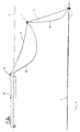
- the seabed is indicated at 1 and the sea surface at 2.
- Figs. 1, 4 and 5 substantially corresponding or similar parts of the whole system according to the invention and the total arrangement involved in a mooring situation with associated operations.
- a ship 10 usually a tanker (40 in Fig. 5), an anchor 3 at the seabed 1 and an anchoring line with two parts 6 and 8 being at a middle portion provided with a buoyant body 7, also denoted line buoy.
- the ship 10 is equipped with mooring means 11 at the bow, without any details being shown more closely at this point.
- the system according to the invention as described so far, is sufficient for the desired mooring of the ship 10, and in this connection involves advantages as already mentioned in the introduction above.
- An important feature of the mooring system is the line buoy 7, which is preferably located at or connected to a middle portion of the total anchoring line 6, 8. It is obvious that buoy 7 does not need to be exactly at the middle of the total line length, but in order that the desired effect be obtained, it is and advantage that the buoy is positioned at a good distance both from the lower end of anchoring line 6 at anchor means 3, and from the upper end of anchoring line 8 at mooring means 11.
- buoy 7 The dimensions of buoy 7 are chosen so that under most conditions or stresses a quite significant angle difference between the adjacent portions of line parts 6 and 8 is established. Thus line part 6 will normally extend upwards from anchor 3 at a clearly smaller angle in relation to the vertical, than the angle at which line part 8 runs out from buoy 7.
- the whole anchoring line 6, 8 may be tightened more than shown e.g. in Fig. 1, so that buoy 7 is pulled deeper into the water and the angle between line parts 6 and 8 can approach more or less 180°.
- buoy 7 may float to the sea surface 2, if the length of line part 6 is larger than the water depth.
- buoy 7 as a rule will be located well immerged under the sea surface. This is per se a very favourable situation for the buoy and the whole system, since the buoy when located deep in the water is less subjected to influence from wind and waves occuring at the sea surface. It is also an important effect of buoy 7 that under substantially all conditions this will maintain anchoring line part 6 tensioned upwards from anchor 3, so that no part of the anchoring line will be lying on the seabed 1.
- this buoy device comprises more than one individual buoy, but still so arranged that there is provided a relatively limited deflection portion more or less at the middle of the total anchoring line.
- the main purpose of such a buoy or buoy device is to provide for a relatively concentrated buoyancy in the anchoring line, which results in a soft or flexible behaviour of the whole mooring system, with reduced dynamic load effects.
- this invention also comprises fluid transfer between the anchor means 3 and the ship 10.
- a relatively flexible hose 9 being extended up to the bow portion of the ship 10, which is there provided with suitable connection means, that may very well be combined with the mooring means 11.
- suitable connection means that may very well be combined with the mooring means 11.
- buoyant elements 9A At a lower portion of hose 9 there are shown buoyant elements 9A, which in this case are provided in a number of three, but can of course vary in number and dimensions depending on the desired shape of hose 9.
- a primary purpose of buoyant elements 9A is to secure that the lower portion of hose 9 is generally always elevated from seabed 1. It is a great advantage that hose 9 runs through the water well underneath anchoring line 6, 8, as illustrated in Fig. 1. Thereby any contact between the two main parts of the system is avoided, in particular so that hose 9 will not be damaged by any part of anchoring line 6, 8.
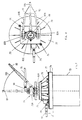
- Figs. 2 and 3 in more detail show a possible and preferred design of the anchor 3 with associated equipment, in particular a swivel device 5 at the top of anchor 3.
- this preferably has the form of a suction anchor, which can be of a design as known per se, and adapted to penetrate into loose masses underneath the actual seabed 1 in order to obtain a strong anchoring effect.
- the suction anchor 2 thus has a downwardly open cylindrical shape.
- a fixed carrier member 13 which supports the actual swivel device 5.
- This has an upper connection member 19 with a pipe bend to which the lower end of hose 9 is connected, e.g. by a flange connection.
- the lower swivel part 18 serves for the attachment of two line parts 6A and 6B as shown more in detail in Fig. 3.
- Line parts or portions 6A and 6B constitute the lower end of a so-called crowfoot having an apex at 6C (Fig. 1) so that the crowfoot as a whole has the shape of a preferably isosceles triangle the base line of which is formed by an arm structure 15A, 15B.
- Arms 15A and 15B have a common horisontal axis 15C and line portions 6A and 6B respectively, are connected to the outer ends of arms 15A and 15B so as to be pivotable about the axis 15C.
- An important purpose of arms 15A and 15B is to provide for a sufficient torque for the swivel movement about the central, vertical axis, depending upon the direction of the mooring force from the ship 10 through the anchoring line 6, 8. Swivel members 18 and 19 are united with respect to rotation.
- hose 9 has a direction outwards and upwards from swivel means 5 at a smaller angle in relation to the horisontal than anchoring line portion 6A.
- hose 9 runs out centrally between line portions 6A and 6B, there is minimal risk of damage to hose 9 by contact with any portion of the anchoring line.
- connection member 19 for hose 9 when this is all installed at the seabed 1.
- Another important feature of the structure consists therein that the more vital parts of the anchor means can be retrieved to the surface for maintenance, repair or replacement.
- Fig. 2 there is indicated a separation or plane showing how the actual suction anchor 3 can be separated from the remaining parts, i.e. the carrier member and the swivel means, whereby the carrier member e.g. by detachable bolt connections can be attached to the top of suction anchor 3.
- the connection of pipeline 14 must be loosened and possibly plugged.
- hose directly upwards centrally from swivel means 5, which implies that such a hose somewhere higher up in the water will have to cross or pass by the anchoring line 6, 8.
- Fig. 2 shows a pipeline 14 connected for supplying e.g. produced fluid, such as hydrocarbons, to the anchor installation 3, namely the stationary carrier member 13 thereof for the swivel means 5.
- Fig. 4 shows a modification of the arrangement in Fig. 1, where the transfer hose 28, 19 i Fig. 4 has not been provided with its own buoyant element, but is suspended from line buoy 7.
- the hose will generally run through the water at a good distance underneath the anchoring line.
- buoy 7 apparently must be dimensioned to have somewhat more buoyancy than in the embodiment of Fig. 1.
- the system of Fig. 4 chould be considered to act as a more integral, unitary system, which may be better maintained under control when the ship 10 moves around the anchoring point during varying weather conditions. This can be advantageous e.g. in view of varying currents at smaller or larger water depth.
- Fig. 5 is based on a system according to the invention being in the principle like the embodiment of Fig. 1, but in Fig. 5 the hose 39 with associated buoyancy elements 38A at the lower portion, is connected to equipment 41 mid-ship of ship 40 with the upper end of the hose.
- Equipment 41 can be connection devices being per se of conventional type, such as a socalled manifold.
- tanker 40 which can have a large capacity, is adapted to cooperate with e.g. a tanker or a barge 50, whereby a fluid load can be transferred through a hose connection 49 from the aft end of ship 40 to the bow of ship 50, at the same time as a mooring 44 is extended between both ships.
- Equpiment units as shown at 45 and 55, respectively, on the ships, can be of conventional design as known per se, for the hose connection 49 and the mooring 44, respectively.
- a suction anchor 63 as in Figs. 2 and 3, but here again there can be a possibility of letting the actual anchor part be based on other types of anchoring principles, e.g. gravitation or piling as mentioned before.
- a frame or plate 64 for supporting swivel means 60.
- This has a rotation axis 60X being preferably also a center line of suction anchor 63.
- the actual fluid swivel 65 in this case is located just above plate 64 and serves to provide fluid connection through a connector 62A for a pipeline extending at the seabed 1 from an underwater installation not being shown.
- connection flange or the like for a flexible hose adapted to be extended to the surface as e.g. hose 9 in Fig. 1.
- a projection 61A from anchoring member 61 is provided with one or more attachment elements 66A for an anchoring line 66 or a yoke or the like to which the anchoring line is attached.
- attachment elements 66A for equalizing the forces in both legs comprised by the yoke or the crowfoot.
- supporting rollers 67 at the lower portion of member 61 corresponding angularly to projection 61A. These supporting rollers are adapted to roll at the upper side of plate 64.
- a guide ring 68 which can have an angle profile, is mounted radially outwards of and axially above the supporting roller 67 for protecting and securing this.
- Figs. 7 and 8 show a preferred embodiment of anchor means according to the invention.
- an anchor member 73 in the form of a suction anchor which on top is provided with a strong frame or plate 74.
- a base part 77 which can be plate shaped and supports a carrier member or structure 78 on which the actual swivel device 70 is mounted.
- base part 77 supports at least one connector 79 for the connection of a pipeline 99 from an installation (not shown) at the seabed 1.
- one or more guide posts 75 are provided on top plate 74 for cooperation with elements on base part 77, during retrieval and returning of the structures and components being carried by base part 77, by means of a surface vessel.
- a central component in swivel device 70 is a swivel housing 70A in which the rotatable fluid connection is arranged, e.g. in a manner known per se.
- fluid communication can be established between pipeline 99, which is stationary, and a flexible hose 76 adapted to be connected to a vessel at the surface, for loading or unloading of hydrocarbons.
- a connector member 88 for hose 76 At the top of swivel device 70 there is shown a connector member 88 for hose 76.
- attachment elements 81A and 81B at either side of the swivel device, with a pivotable mounting of two legs 80A and 80B being incorporating in a yoke 80. As shown in Fig. 8 this has a common apex 80C with means for cooperating with the lower end of an anchoring line (not shown).
- hose 76 When by means of the anchoring line the surface vessel mentioned, is moored with the anchor device as shown in Figs. 7 and 8, with a simultaneous hose connection 76 for fluid transfer, the weathering movements of the ship under the influence of wind, waves and current, will involve angular movement or rotation of the whole swivel device about the vertical axis shown, whereby hose 76 preferably all the way through the water up to the surface runs lower than the anchoring line and more or less in the same vertical plane as this. Adjacent to swivel device 70 it is obvious that hose 76 with connector 88 is located centrally underneath yoke 80, so that this will not contact the hose or its connection at the top of swivel device 70.
- journalling of the whole structure including the swivel housing 70A, and this journal arrangement is adapted to take up the forces and bending moments being due to a connected fluid hose 76 and the anchoring line as the case may be.
- the yoke 80 can also be swung up and down about a horisontal axis 81C (Fig. 8) between attachment elements 82A and 81B, which can comprise horisontal axle studs coinciding with axis 81C.
- a horisontal axis 81C FIG. 7
- attachment elements 82A and 81B FIG. 8
- horisontal axle studs coinciding with axis 81C.
- 100 in Fig. 7 there is shown a possible angular range within which yoke 80 can move, with one angular position 80' directed vertically upwards. This position of yoke 80 is of interest, inter alia, when retrieving and lowering the above mentioned vital parts of the anchor device, as will be explained below with reference to Fig. 9.
- the system described here can e.g. be intended for operation at water depths from 150-300 meters. At a depth of e.g. 200 meters the two parts 6 and 8 of the total anchoring line can typically be 160 meters and 200 meters respectively, in a favourable practical embodiment.
- anchor 3 is permanent, this does not mean e.g. that a suction anchor or a gravitation anchor must remain forever at the seabed 1, upon being installed. As known even such relatively fixed installations at the seabed can be removed by suitable means and equipment.
- a permanent anchor device in this context means a more permanent anchor than what is typically carried by a ship and can be thrown from this or hauled into the ship by means of its normal anchor capstan.
- a method of installation of an anchor device in the system as explained above, according to the invention with advantage can consist in that the anchor is suspended at the end of an anchor chain or wire belonging to a generally regular anchor capstan or winch of the ship concerned, being employed for lowering the anchor to a predetermined point at the seabed.
- Figs. 7 and 8 For illustrating the separation of the main parts of the anchor device as mentioned above, the preferred embodiment according to Figs. 7 and 8 is taken as a background for Fig. 9. In the latter the suction anchor 73 with top plate 74, base part 77 with carrier member 78 are found, and the actual swivel device 70 has only been indicated schematically. Besides the connector 79 is shown after disconnection of pipeline 99 with associated connector part 99A. From guide posts 75, guide lines 95 are extended up to the surface vessel concerned, for guiding base part 77 with all components carried thereby, up to the surface, and conversely for lowering these parts of the structure upon a possible repair or the like, for renewed installation on anchor member 73 with top plate 74. The operations involved in this connection can be more or less conventional, but a specific method is explained above, namely by employing the regular anchor capstan of the ship concerned as well as an anchor chain or wire.
- the hose or riser 9 can be paid out from an assisting auxiliary vessel.
- Fig. 1 there is illustrated an apex 6C of the crowfoot as also explained with reference to Figs. 2 and 3, but it is obvious that the position of apex 6C can vary considerably, and possibly the apex can be adjacent to or on the buoyant body or buoy 7.
- apex 6C can vary considerably, and possibly the apex can be adjacent to or on the buoyant body or buoy 7.
Landscapes
- Engineering & Computer Science (AREA)
- Mechanical Engineering (AREA)
- Chemical & Material Sciences (AREA)
- Ocean & Marine Engineering (AREA)
- Combustion & Propulsion (AREA)
- Life Sciences & Earth Sciences (AREA)
- Geology (AREA)
- Mining & Mineral Resources (AREA)
- Environmental & Geological Engineering (AREA)
- Geochemistry & Mineralogy (AREA)
- General Life Sciences & Earth Sciences (AREA)
- Fluid Mechanics (AREA)
- Physics & Mathematics (AREA)
- Laying Of Electric Cables Or Lines Outside (AREA)
- Earth Drilling (AREA)
- Revetment (AREA)
- Ship Loading And Unloading (AREA)
- Joints Allowing Movement (AREA)
- Other Liquid Machine Or Engine Such As Wave Power Use (AREA)
Claims (15)
- Système pour le chargement ou le déchargement de navires impliqués dans des opérations relatives à des activités de pétrole et de gaz, le système comprenant: des moyens d'amarrage (11) à un bateau (10, 40); une ancre permanente (3) située au fond de la mer (1) et étant en communication fluidique avec une installation sous-marine; et au moins une ligne d'ancrage (6, 8) raccordant l'ancre (3) aux moyens d'amarrage (11) sur le bateau (10), et dans lequel: l'ancré (3) comporte un (des) dispositif(s) de pivotement (5, 18, 70); la portion inférieure (6) de la ligne d'ancrage (6, 8) est raccordée au dispositif de pivotement (5, 19); et de préférence un corps flottant (7) est attaché à la portion médiane de la ligne d'ancrage (6, 8); le système comprenant également un tuyau (9, 28, 29, 39) dont l'extrémité inférieure est raccordée au dispositif de pivotement (5, 19), et une unité de communication fluidique (11, 41) sur le bateau (10, 40), l'unité de communication fluidique (11, 41) étant raccordée à l'extrémité supérieure du tuyau (9, 28, 29, 39); caractérisé en ce que: la portion inférieure (6) de la ligne d'ancrage (6, 8) présente une barre de levier (6A, 6B, 6C) et le dispositif de pivotement (5, 18) a deux bras en porte à faux (15A, 15B) ayant des extrémités extérieures auxquelles les lignes (6A, 6B) de la barre de levier (6A, 6B, 6C) sont attachées; l'ancre comprend un élément de base de type plaque ou cadre (77) reposant au sommet (74) d'une portion d'ancre inférieure (73) et pouvant être séparé de celle-ci; l'élément de base (77) étant pourvu d'un élément de support (78) pour le dispositif de pivotement (70); et dans lequel l'élément de base (77) porte un connecteur (79) pour un pipeline (99) à partir d'une installation située au fond de la mer; et un boítier de pivotement extérieur (70A) est arrangé de manière à pouvoir tourner par rapport à l'élément d'ancre (73) et porte l'élément de connexion (88), et un moyen de tourillon pour le boítier de pivotement (70A) est apte à transférer des forces de flexion dues à un tuyau de fluide raccordé (76) et éventuellement à une ligne d'ancrage à l'élément d'ancrage (73), par l'intermédiaire de l'élément de support (78) et de l'élément de base (77).
- Système suivant la revendication 1, caractérisé en ce que l'ancré (3) est une ancre par aspiration (3), une ancre par gravité ou une ancre d'empilement.
- Système suivant la revendication 1 ou la revendication 2, caractérisé en ce que la barre de levier (6A, 6B, 6C) peut pivoter autour d'un axe (15C) entre les bras en porte à faux (15A, 15B).
- Système suivant l'une quelconque des revendications précédentes, caractérisé en ce que le tuyau (9, 39) est pourvu d'éléments flottants (9A, 39A), de préférence à une portion inférieure de celui-ci.
- Système suivant l'une quelconque des revendications 1 à 3, caractérisé en ce que le tuyau (28, 29) est suspendu au corps flottant (7) sur la ligne d'ancrage (6, 8), de préférence à une portion médiane de celle-ci.
- Système suivant l'une quelconque des revendications précédentes, caractérisé en ce que l'extrémité inférieure du tuyau (9) est raccordée d'une façon centrale au dispositif de pivotement (5, 19).
- Système suivant la revendication 6, caractérisé en ce que le tuyau s'étend à partir du dispositif de pivotement d'une façon centrale entre les lignes de la barre de levier (6A, 6B).
- Système suivant la revendication 6 ou la revendication 7, caractérisé en ce que le tuyau (9), durant substantiellement toutes les conditions d'ancrage, s'étend à partir des moyens de pivotement (5) à une position angulaire plus horizontale que la position angulaire de la portion inférieure (6, 6A, 6B) de la ligne d'ancrage.
- Système suivant l'une quelconque des revendications précédentes, caractérisé en ce que le tuyau (9, 28, 29, 39) s'étend à travers l'eau en dessous de la ligne d'ancrage (6, 8), du fait de sa longueur et de la flottabilité exercée (7, 9A, 39A).
- Ancre pour une installation au fond de l'eau pour l'amarrage et le chargement ou le déchargement de navires ou autres bateaux impliqués dans des opérations relatives à des activités maritimes de pétrole ou de gaz, comprenant un dispositif de pivotement (5) pourvu d'éléments de fixation (15A, 15B) pour au moins une ligne d'ancrage (6A, 6B) à partir du bateau, l'axe de rotation du dispositif de pivotement étant approximativement vertical au fond de la mer (1), permettant ainsi au dispositif de pivotement de tourner dans un plan approximativement parallèle au fond de la mer, et dans laquelle le dispositif de pivotement (5) comprend un élément de pivotement (19) pour un tuyau de fluide (9) et un passage traversant de fluide arrangé de manière à être raccordé à une installation au fond de la mer, caractérisée en ce que les éléments de fixation (15A, 15B) comprennent deux bras en porte à faux ayant des extrémités extérieures aptes à être attachées aux lignes d'ancrage (6, 8); une portion d'ancre inférieure (3, 63, 73) d'une part et substantiellement toutes les autres portions d'autre part, y compris le dispositif de pivotement (5, 18, 19), peuvent être séparées au moyen d'éléments de jonction détachables, de telle sorte que les autres portions puissent être récupérées à la surface pour leur entretien, leur réparation ou leur remplacement; l'ancré comprend un élément de base de type plaque ou cadre (77) reposant au sommet (74) de la portion d'ancré inférieure (73) et pouvant être séparé de celle-ci; l'élément de base (77) étant pourvu d'un élément de support (78) pour le dispositif de pivotement (70); et dans laquelle l'élément de base (77) porte un connecteur (79) pour un pipeline (99) à partir d'une installation située au fond de la mer; et un boítier de pivotement extérieur (70A) est arrangé de manière à pouvoir tourner par rapport à l'élément d'ancre (73) et porte l'élément de connexion (88), et un moyen de tourillon pour le boítier de pivotement (70A) est apte à transférer des forces de flexion dues à un tuyau de fluide raccordé (76) et éventuellement à une ligne d'ancrage à l'élément d'ancrage (73), par l'intermédiaire de l'élément de support (78) et de l'élément de base (77).
- Ancre suivant la revendication 10, caractérisée en ce que les éléments de fixation (15A, 15B) sont aptes à être situés à un niveau plus bas que l'élément de connexion (19) dans la position opérationnelle au fond de la mer.
- Système d'ancrage suivant la revendication 10 ou la revendication 11, caractérisé en ce que l'ancre est basée sur un effet d'aspiration, un effet de gravité ou un effet d'empilement au fond de la mer.
- Ancre suivant la revendication 10, caractérisée en ce qu'elle comprend un élément principal de transfert de force (61) présentant une saillie radiale (61A) qui porte les éléments de fixation (61A), et au moins un galet de support (67) relié à l'élément principal et situé essentiellement en dessous de la saillie (61A), et étant apte à rouler dans un guide (68) au sommet (64) de l'élément d'ancre inférieur (63).
- Ancre suivant l'une quelconque des revendications 10 à 13, caractérisée en ce que le connecteur (79) permet la connexion et la déconnexion du pipeline (99).
- Ancre suivant l'une quelconque des revendications 10 à 14, caractérisée par la présence d'un manche (80) ayant deux bras (80A, 80B), dont les extrémités extérieures sont raccordées de façon pivotante aux éléments de fixation (81A, 81B) qui sont situés de part et d'autre du dispositif de pivotement (70), et les extrémités opposées des bras (80A, 80B) sont raccordées (80C) à une ligne d'ancrage.
Applications Claiming Priority (3)
| Application Number | Priority Date | Filing Date | Title |
|---|---|---|---|
| NO960698A NO960698D0 (no) | 1996-02-21 | 1996-02-21 | System til forankring av skip |
| NO960698 | 1996-02-21 | ||
| PCT/NO1996/000202 WO1997030888A1 (fr) | 1996-02-21 | 1996-08-07 | Systeme pour le chargement de navires en mer |
Publications (2)
| Publication Number | Publication Date |
|---|---|
| EP0880450A1 EP0880450A1 (fr) | 1998-12-02 |
| EP0880450B1 true EP0880450B1 (fr) | 2003-02-26 |
Family
ID=19899069
Family Applications (3)
| Application Number | Title | Priority Date | Filing Date |
|---|---|---|---|
| EP96933665A Expired - Lifetime EP0877702B1 (fr) | 1996-02-21 | 1996-08-07 | Systeme d'ancrage pour navires |
| EP96931304A Expired - Lifetime EP0877701B1 (fr) | 1996-02-21 | 1996-08-07 | Systeme pour la production d'hydrocarbures |
| EP96933664A Expired - Lifetime EP0880450B1 (fr) | 1996-02-21 | 1996-08-07 | Systeme pour le chargement de navires en mer |
Family Applications Before (2)
| Application Number | Title | Priority Date | Filing Date |
|---|---|---|---|
| EP96933665A Expired - Lifetime EP0877702B1 (fr) | 1996-02-21 | 1996-08-07 | Systeme d'ancrage pour navires |
| EP96931304A Expired - Lifetime EP0877701B1 (fr) | 1996-02-21 | 1996-08-07 | Systeme pour la production d'hydrocarbures |
Country Status (12)
| Country | Link |
|---|---|
| US (3) | US6332500B1 (fr) |
| EP (3) | EP0877702B1 (fr) |
| JP (3) | JP3910640B2 (fr) |
| KR (3) | KR100450541B1 (fr) |
| CN (3) | CN1100698C (fr) |
| AU (3) | AU721382B2 (fr) |
| BR (3) | BR9612528A (fr) |
| CA (3) | CA2246670C (fr) |
| DK (3) | DK0877701T3 (fr) |
| NO (1) | NO960698D0 (fr) |
| RU (3) | RU2185994C2 (fr) |
| WO (3) | WO1997030887A1 (fr) |
Cited By (1)
| Publication number | Priority date | Publication date | Assignee | Title |
|---|---|---|---|---|
| CN105889754A (zh) * | 2016-06-02 | 2016-08-24 | 连云港远洋流体装卸设备有限公司 | 可伸缩式岸基lng加注臂 |
Families Citing this family (49)
| Publication number | Priority date | Publication date | Assignee | Title |
|---|---|---|---|---|
| NO960698D0 (no) * | 1996-02-21 | 1996-02-21 | Statoil As | System til forankring av skip |
| NO305217B1 (no) | 1996-08-27 | 1999-04-19 | Norske Stats Oljeselskap | Svivelanordning |
| GB9621031D0 (en) * | 1996-10-09 | 1996-11-27 | Coflexip Stena Offshore Ltd | Marine mooring system |
| US6457908B1 (en) * | 1997-05-06 | 2002-10-01 | Delmar Systems, Inc. | Method and apparatus for suction anchor and mooring deployment and connection |
| FR2768457B1 (fr) * | 1997-09-12 | 2000-05-05 | Stolt Comex Seaway | Dispositif de transport sous-marin de produits petroliers a colonne montante |
| NO314133B1 (no) | 1998-12-07 | 2003-02-03 | Master Marine As | Fremgangsmåte ved lastoverföringsoperasjoner til havs og flyter for transport, installasjon og fjerning av konstruksjonselementer til havs |
| NO311417B1 (no) * | 1999-03-04 | 2001-11-26 | Advanced Prod & Loading As | System for forankring av et fartöy |
| GB2347724B (en) * | 1999-03-11 | 2001-01-17 | Bluewater Terminal Systems Nv | Apparatus for transferring fluid between the seabed and a floating vessel |
| NO312358B1 (no) * | 2000-07-20 | 2002-04-29 | Navion Asa | Offshore laste- eller produksjonssystem for et dynamisk posisjonert skip |
| US6685396B1 (en) * | 2000-11-16 | 2004-02-03 | Billy J. Bergeron | Method and apparatus for suction anchor and mooring deployment and connection |
| US6997643B2 (en) * | 2003-10-30 | 2006-02-14 | Sbm-Imodco Inc. | LNG tanker offloading in shallow water |
| US20060156744A1 (en) * | 2004-11-08 | 2006-07-20 | Cusiter James M | Liquefied natural gas floating storage regasification unit |
| CN1967618B (zh) * | 2005-11-14 | 2011-06-29 | 中国船舶重工集团公司第七一○研究所 | 实时传输潜标装置 |
| KR100747373B1 (ko) * | 2006-07-28 | 2007-08-07 | 대우조선해양 주식회사 | Lng 운송선의 설비 정비를 위한 설비 운반 시스템 및방법과 lng 운송선 |
| NO333841B1 (no) | 2006-10-06 | 2013-09-30 | Framo Eng As | Lastesystem |
| US7383785B1 (en) | 2006-11-22 | 2008-06-10 | Brian Schmidt | Mooring system for watercraft |
| NO20072021L (no) * | 2007-04-20 | 2008-10-21 | Seabed Rig As | Fremgangsmate og anordning for intervensjon i en undervanns produksjonsbronn |
| US7690135B2 (en) * | 2007-09-23 | 2010-04-06 | Technip France | Deep sea mining riser and lift system |
| US20090123235A1 (en) * | 2007-11-08 | 2009-05-14 | Technip France | Outer pipe sleeve for a sea floor mooring pile |
| US8847421B2 (en) | 2008-07-16 | 2014-09-30 | Anadarko Petroleum Corporation | Subsystems for a water current power generation system |
| US8622137B2 (en) * | 2008-08-21 | 2014-01-07 | Shell Oil Company | Subsea structure installation or removal |
| EP2424776A4 (fr) * | 2009-04-30 | 2017-03-29 | Exxonmobil Upstream Research Company | Système d'amarrage pour navire arctique flottant |
| BR112012006458A2 (pt) * | 2009-09-25 | 2016-04-26 | Aker Subsea As | manifolde de válvulas de produção e estação de bomba multifásica integrados |
| CN102821673B (zh) | 2009-11-10 | 2016-06-08 | 纽瓦西弗公司 | 牵开器系统 |
| KR101681707B1 (ko) * | 2010-06-29 | 2016-12-02 | 대우조선해양 주식회사 | 냉각용 해수를 사용하는 부유식 해상 구조물 |
| KR101681708B1 (ko) * | 2010-06-29 | 2016-12-01 | 대우조선해양 주식회사 | 냉각용 해수를 사용하는 부유식 해상 구조물 |
| NO332121B1 (no) * | 2010-11-09 | 2012-07-02 | Aker Subsea As | Havbunnsanker |
| US9211939B2 (en) | 2011-02-05 | 2015-12-15 | Carlos Torres | Anchor for boats |
| EP2899361B1 (fr) * | 2011-04-18 | 2018-08-08 | Magma Global Limited | Système de tuyau sous-marin |
| US9307972B2 (en) | 2011-05-10 | 2016-04-12 | Nuvasive, Inc. | Method and apparatus for performing spinal fusion surgery |
| SG11201502537VA (en) * | 2012-10-30 | 2015-05-28 | Exxonmobil Upstream Res Co | System and method for obstacle avoidance during hydrocarbon operations |
| SI3013676T1 (en) * | 2013-06-28 | 2018-04-30 | Stolt-Nielsen Tm B.V. | Procedure for constructing a tanker |
| WO2015044667A1 (fr) * | 2013-09-26 | 2015-04-02 | Edmunds, James | Ancre à succion |
| GB2543468B (en) | 2014-08-13 | 2021-11-03 | Nuvasive Inc | Minimally disruptive retractor and associated methods for spinal surgery |
| US9939421B2 (en) * | 2014-09-10 | 2018-04-10 | Saudi Arabian Oil Company | Evaluating effectiveness of ceramic materials for hydrocarbons recovery |
| KR101690983B1 (ko) * | 2014-11-05 | 2016-12-29 | 삼성중공업 주식회사 | 무어링장치 |
| US9671231B2 (en) * | 2015-07-20 | 2017-06-06 | Technip France | Monitoring system and method for vessel mooring |
| CN105019471A (zh) * | 2015-08-13 | 2015-11-04 | 山东科技大学 | 一种倾斜式桶形基础锚泊系统及其施工方法 |
| KR101747312B1 (ko) * | 2015-11-12 | 2017-06-15 | 오토렉스 주식회사 | 부유구조물의 계류장치 |
| CN105857520A (zh) * | 2016-03-22 | 2016-08-17 | 浙江海洋学院 | 一种船舶的锚泊定位结构 |
| WO2018134252A1 (fr) * | 2017-01-19 | 2018-07-26 | Single Buoy Moorings Inc. | Plaque d'entraînement d'une tourelle d'un navire |
| CN108382530A (zh) * | 2018-03-16 | 2018-08-10 | 广州船舶及海洋工程设计研究院 | 一种单点系泊船体偏荡运动控制装置 |
| CN109728474B (zh) * | 2018-12-29 | 2020-08-04 | 中国船舶重工集团公司第七一九研究所 | 基于rov引导的插接装置及其插接方法 |
| US11597478B2 (en) * | 2019-05-29 | 2023-03-07 | Sofec, Inc. | Systems for handling one or more elongated members and methods for using same |
| US11619097B2 (en) | 2021-05-24 | 2023-04-04 | Saudi Arabian Oil Company | System and method for laser downhole extended sensing |
| US11725504B2 (en) | 2021-05-24 | 2023-08-15 | Saudi Arabian Oil Company | Contactless real-time 3D mapping of surface equipment |
| FR3140064A1 (fr) * | 2022-09-22 | 2024-03-29 | Eti Group | Installation d’exploitation de fluides, notamment sur une plateforme offshore, à dispositif joint tournant immergé |
| CN115535196B (zh) * | 2022-09-29 | 2025-05-30 | 江苏亚星锚链股份有限公司 | 一种用于系泊附件的水下拆装模块 |
| CN115535156B (zh) * | 2022-10-18 | 2025-04-25 | 中船黄埔文冲船舶有限公司 | 一种海补管偏向浮力装置及其使用方法 |
Family Cites Families (30)
| Publication number | Priority date | Publication date | Assignee | Title |
|---|---|---|---|---|
| US3067716A (en) * | 1961-03-18 | 1962-12-11 | Internat Marine And Oil Dev Co | Mooring devices |
| GB1177926A (en) | 1966-05-06 | 1970-01-14 | Shell Int Research | One Point Mooring System for Loading Fluids into or Unloading Fluids from a Ship |
| US3411473A (en) * | 1966-12-19 | 1968-11-19 | Texaco Inc | Deepwater anchor |
| US3455270A (en) * | 1968-05-08 | 1969-07-15 | Exxon Research Engineering Co | Protective dome for underwater mooring swivel |
| US3608652A (en) * | 1968-11-13 | 1971-09-28 | A Z Int Tool Co | Underwater drilling apparatus |
| CA936374A (en) * | 1969-05-06 | 1973-11-06 | Lecomte Claude | Floating systems, especially mooring buoys, for anchoring to the sea-bed |
| US3670686A (en) * | 1970-09-22 | 1972-06-20 | David G Reynolds | Submerged mooring system |
| US3750723A (en) * | 1971-01-04 | 1973-08-07 | Air Logistics Corp | Single point mooring system |
| US3840927A (en) * | 1973-04-27 | 1974-10-15 | Imodco | Swivel unit for mooring and cargo transfer system |
| US4065822A (en) * | 1976-02-27 | 1978-01-03 | Texaco Inc. | Single point mooring with strain relief anchoring |
| US4081872A (en) * | 1976-08-30 | 1978-04-04 | Sofec, Inc. | Submerged self-stabilized cargo hose arm for a single point mooring system |
| US4130076A (en) * | 1977-03-17 | 1978-12-19 | Vetco, Inc. | Single point mooring apparatus |
| IT1122786B (it) * | 1979-08-17 | 1986-04-23 | Magnanini Umberto | Struttura di ormeggio rotante temporaneo o permanente per navi o natanti |
| USRE33434E (en) * | 1979-09-04 | 1990-11-13 | Amtel, Inc. | Rapidly installable mooring and cargo system |
| US4509448A (en) * | 1983-10-13 | 1985-04-09 | Sonat Offshore Drilling Inc. | Quick disconnect/connect mooring method and apparatus for a turret moored drillship |
| US4727819A (en) * | 1984-04-24 | 1988-03-01 | Amtel, Inc. | Single line mooring system |
| US4602586A (en) * | 1984-12-24 | 1986-07-29 | Exxon Production Research Co. | Motion decoupling mechanism for fluid swivel stack |
| FR2592456B1 (fr) * | 1985-12-30 | 1988-08-26 | Inst Francais Du Petrole | Dispositif pour eviter la torsion d'une ligne flexible |
| EP0251488B1 (fr) * | 1986-06-05 | 1991-11-06 | Bechtel Limited | Dispositif de colonnes montantes souples et son procédé d'utilisation |
| GB2200938B (en) * | 1987-02-12 | 1992-01-22 | Heerema Engineering | Control system |
| SU1556999A1 (ru) * | 1987-02-24 | 1990-04-15 | Московский Геологоразведочный Институт Им.Серго Орджоникидзе | Гидростатический корь |
| SU1623914A1 (ru) * | 1987-11-03 | 1991-01-30 | Архангельский лесотехнический институт им.В.В.Куйбышева | Устройство дл заглублени корей |
| SU1539128A1 (ru) * | 1988-05-23 | 1990-01-30 | Предприятие П/Я В-8195 | Якорь плавучего средства |
| NO176129C (no) * | 1992-05-25 | 1997-07-08 | Norske Stats Oljeselskap | System for anvendelse ved offshore petroleumsproduksjon |
| US5505560A (en) * | 1993-10-26 | 1996-04-09 | Offshore Energie Development Corporation (Oecd) | Fluid transfer system for an offshore moored floating unit |
| WO1996011134A1 (fr) * | 1994-10-07 | 1996-04-18 | Single Buoy Moorings Inc. | Bouee immergee d'amarrage a chaine catenaire |
| NO960698D0 (no) * | 1996-02-21 | 1996-02-21 | Statoil As | System til forankring av skip |
| US5704307A (en) * | 1996-03-13 | 1998-01-06 | Aker Marine, Inc. | Taut leg mooring system |
| IT1283548B1 (it) * | 1996-03-21 | 1998-04-22 | Tecnomare Spa | Metodo e sistema di monormeggio per attracco di navi in mare aperto |
| US5875395A (en) * | 1996-10-09 | 1999-02-23 | At&T Wireless Services Inc. | Secure equipment automation using a personal base station |
-
1996
- 1996-02-21 NO NO960698A patent/NO960698D0/no unknown
- 1996-08-07 RU RU98117239/28A patent/RU2185994C2/ru active
- 1996-08-07 KR KR10-1998-0706482A patent/KR100450541B1/ko not_active Expired - Lifetime
- 1996-08-07 KR KR1019980706481A patent/KR19990087093A/ko not_active Withdrawn
- 1996-08-07 RU RU98117234/28A patent/RU2196701C2/ru active
- 1996-08-07 BR BR9612528A patent/BR9612528A/pt not_active IP Right Cessation
- 1996-08-07 CA CA002246670A patent/CA2246670C/fr not_active Expired - Lifetime
- 1996-08-07 JP JP53003097A patent/JP3910640B2/ja not_active Expired - Lifetime
- 1996-08-07 WO PCT/NO1996/000201 patent/WO1997030887A1/fr not_active Ceased
- 1996-08-07 AU AU72299/96A patent/AU721382B2/en not_active Expired
- 1996-08-07 DK DK96931304T patent/DK0877701T3/da active
- 1996-08-07 US US09/125,361 patent/US6332500B1/en not_active Expired - Lifetime
- 1996-08-07 EP EP96933665A patent/EP0877702B1/fr not_active Expired - Lifetime
- 1996-08-07 AU AU72300/96A patent/AU711621B2/en not_active Expired
- 1996-08-07 AU AU70025/96A patent/AU714682B2/en not_active Expired
- 1996-08-07 EP EP96931304A patent/EP0877701B1/fr not_active Expired - Lifetime
- 1996-08-07 CA CA002246685A patent/CA2246685C/fr not_active Expired - Lifetime
- 1996-08-07 WO PCT/NO1996/000202 patent/WO1997030888A1/fr not_active Ceased
- 1996-08-07 CN CN96180055A patent/CN1100698C/zh not_active Expired - Lifetime
- 1996-08-07 RU RU98117237/28A patent/RU2198815C2/ru active
- 1996-08-07 WO PCT/NO1996/000203 patent/WO1997030889A1/fr not_active Ceased
- 1996-08-07 US US09/125,360 patent/US6109197A/en not_active Expired - Lifetime
- 1996-08-07 CN CN96180056A patent/CN1095783C/zh not_active Expired - Lifetime
- 1996-08-07 CA CA002246686A patent/CA2246686C/fr not_active Expired - Lifetime
- 1996-08-07 BR BR9612527A patent/BR9612527A/pt not_active IP Right Cessation
- 1996-08-07 JP JP53003197A patent/JP3886537B2/ja not_active Expired - Lifetime
- 1996-08-07 JP JP53003297A patent/JP3803383B2/ja not_active Expired - Lifetime
- 1996-08-07 EP EP96933664A patent/EP0880450B1/fr not_active Expired - Lifetime
- 1996-08-07 CN CN96180057A patent/CN1095784C/zh not_active Expired - Lifetime
- 1996-08-07 BR BR9612516A patent/BR9612516A/pt not_active IP Right Cessation
- 1996-08-07 KR KR1019980706480A patent/KR19990087092A/ko not_active Withdrawn
- 1996-08-07 DK DK96933665T patent/DK0877702T3/da active
- 1996-08-07 DK DK96933664T patent/DK0880450T3/da active
- 1996-08-09 US US09/125,459 patent/US6227138B1/en not_active Expired - Lifetime
Cited By (2)
| Publication number | Priority date | Publication date | Assignee | Title |
|---|---|---|---|---|
| CN105889754A (zh) * | 2016-06-02 | 2016-08-24 | 连云港远洋流体装卸设备有限公司 | 可伸缩式岸基lng加注臂 |
| CN105889754B (zh) * | 2016-06-02 | 2018-05-25 | 连云港远洋流体装卸设备有限公司 | 可伸缩式岸基lng加注臂 |
Also Published As
Similar Documents
| Publication | Publication Date | Title |
|---|---|---|
| EP0880450B1 (fr) | Systeme pour le chargement de navires en mer | |
| US5044297A (en) | Disconnectable mooring system for deep water | |
| EP2256025B1 (fr) | Système de recouvrement | |
| US5794700A (en) | CAM fluid transfer system | |
| AU624056B2 (en) | Offshore loading system | |
| JPS619387A (ja) | 船係留装置 | |
| US5893334A (en) | Method and apparatus for mooring floating storage vessels | |
| US5816183A (en) | Submerged CALM buoy | |
| US6932015B2 (en) | Mooring arrangement | |
| KR100423268B1 (ko) | 얕은 물에서 사용하는 선적/하적 부체의 장치 | |
| US6685519B1 (en) | System for transferring fluids and methods for installing, modifying and operating system | |
| De Boom | The development of turret mooring systems for floating production units | |
| NO147669B (no) | Anordning til fortoeyning av et sjoegaaende fartoey |
Legal Events
| Date | Code | Title | Description |
|---|---|---|---|
| PUAI | Public reference made under article 153(3) epc to a published international application that has entered the european phase |
Free format text: ORIGINAL CODE: 0009012 |
|
| 17P | Request for examination filed |
Effective date: 19980813 |
|
| AK | Designated contracting states |
Kind code of ref document: A1 Designated state(s): DK FR GB IE NL |
|
| 17Q | First examination report despatched |
Effective date: 20000203 |
|
| GRAG | Despatch of communication of intention to grant |
Free format text: ORIGINAL CODE: EPIDOS AGRA |
|
| GRAG | Despatch of communication of intention to grant |
Free format text: ORIGINAL CODE: EPIDOS AGRA |
|
| GRAH | Despatch of communication of intention to grant a patent |
Free format text: ORIGINAL CODE: EPIDOS IGRA |
|
| GRAH | Despatch of communication of intention to grant a patent |
Free format text: ORIGINAL CODE: EPIDOS IGRA |
|
| GRAA | (expected) grant |
Free format text: ORIGINAL CODE: 0009210 |
|
| RIN1 | Information on inventor provided before grant (corrected) |
Inventor name: SYVERTSEN, KARE Inventor name: SMEDAL, ARNE Inventor name: BREIVIK, KARE |
|
| AK | Designated contracting states |
Designated state(s): DK FR GB IE NL |
|
| REG | Reference to a national code |
Ref country code: GB Ref legal event code: FG4D |
|
| REG | Reference to a national code |
Ref country code: IE Ref legal event code: FG4D |
|
| REG | Reference to a national code |
Ref country code: DK Ref legal event code: T3 |
|
| ET | Fr: translation filed | ||
| PLBE | No opposition filed within time limit |
Free format text: ORIGINAL CODE: 0009261 |
|
| STAA | Information on the status of an ep patent application or granted ep patent |
Free format text: STATUS: NO OPPOSITION FILED WITHIN TIME LIMIT |
|
| 26N | No opposition filed |
Effective date: 20031127 |
|
| REG | Reference to a national code |
Ref country code: FR Ref legal event code: TP Owner name: STATOIL PETROLEUM AS, NO Effective date: 20130704 Ref country code: FR Ref legal event code: CJ Effective date: 20130704 Ref country code: FR Ref legal event code: CD Owner name: STATOIL PETROLEUM AS, NO Effective date: 20130704 |
|
| REG | Reference to a national code |
Ref country code: GB Ref legal event code: 732E Free format text: REGISTERED BETWEEN 20131107 AND 20131113 |
|
| REG | Reference to a national code |
Ref country code: NL Ref legal event code: TD Effective date: 20131220 Ref country code: NL Ref legal event code: SD Effective date: 20131220 |
|
| REG | Reference to a national code |
Ref country code: FR Ref legal event code: PLFP Year of fee payment: 20 |
|
| PGFP | Annual fee paid to national office [announced via postgrant information from national office to epo] |
Ref country code: NL Payment date: 20150809 Year of fee payment: 20 |
|
| PGFP | Annual fee paid to national office [announced via postgrant information from national office to epo] |
Ref country code: DK Payment date: 20150811 Year of fee payment: 20 Ref country code: IE Payment date: 20150810 Year of fee payment: 20 Ref country code: GB Payment date: 20150805 Year of fee payment: 20 |
|
| PGFP | Annual fee paid to national office [announced via postgrant information from national office to epo] |
Ref country code: FR Payment date: 20150629 Year of fee payment: 20 |
|
| REG | Reference to a national code |
Ref country code: NL Ref legal event code: MK Effective date: 20160806 |
|
| REG | Reference to a national code |
Ref country code: DK Ref legal event code: EUP Effective date: 20160807 |
|
| REG | Reference to a national code |
Ref country code: GB Ref legal event code: PE20 Expiry date: 20160806 |
|
| REG | Reference to a national code |
Ref country code: IE Ref legal event code: MK9A |
|
| PG25 | Lapsed in a contracting state [announced via postgrant information from national office to epo] |
Ref country code: GB Free format text: LAPSE BECAUSE OF EXPIRATION OF PROTECTION Effective date: 20160806 Ref country code: IE Free format text: LAPSE BECAUSE OF EXPIRATION OF PROTECTION Effective date: 20160807 |