EP0880796B1 - Lampenfassung und beleuchtungseinheit mit einer lampenfassung - Google Patents
Lampenfassung und beleuchtungseinheit mit einer lampenfassung Download PDFInfo
- Publication number
- EP0880796B1 EP0880796B1 EP97943101A EP97943101A EP0880796B1 EP 0880796 B1 EP0880796 B1 EP 0880796B1 EP 97943101 A EP97943101 A EP 97943101A EP 97943101 A EP97943101 A EP 97943101A EP 0880796 B1 EP0880796 B1 EP 0880796B1
- Authority
- EP
- European Patent Office
- Prior art keywords
- lampholder
- contacts
- terminal
- lamp
- power supply
- Prior art date
- Legal status (The legal status is an assumption and is not a legal conclusion. Google has not performed a legal analysis and makes no representation as to the accuracy of the status listed.)
- Expired - Lifetime
Links
- 239000004020 conductor Substances 0.000 claims description 21
- 238000004804 winding Methods 0.000 claims description 10
- 229910052751 metal Inorganic materials 0.000 claims description 7
- 239000002184 metal Substances 0.000 claims description 7
- 230000003071 parasitic effect Effects 0.000 description 9
- 101100397044 Xenopus laevis invs-a gene Proteins 0.000 description 5
- 101100397045 Xenopus laevis invs-b gene Proteins 0.000 description 3
- 230000002349 favourable effect Effects 0.000 description 2
- 238000005259 measurement Methods 0.000 description 2
- RYGMFSIKBFXOCR-UHFFFAOYSA-N Copper Chemical compound [Cu] RYGMFSIKBFXOCR-UHFFFAOYSA-N 0.000 description 1
- 238000005452 bending Methods 0.000 description 1
- 239000000470 constituent Substances 0.000 description 1
- 238000010276 construction Methods 0.000 description 1
- 229910052802 copper Inorganic materials 0.000 description 1
- 239000010949 copper Substances 0.000 description 1
- QSHDDOUJBYECFT-UHFFFAOYSA-N mercury Chemical compound [Hg] QSHDDOUJBYECFT-UHFFFAOYSA-N 0.000 description 1
- 229910052753 mercury Inorganic materials 0.000 description 1
- 230000005012 migration Effects 0.000 description 1
- 238000013508 migration Methods 0.000 description 1
- 238000005192 partition Methods 0.000 description 1
Images

Classifications
-
- H—ELECTRICITY
- H01—ELECTRIC ELEMENTS
- H01R—ELECTRICALLY-CONDUCTIVE CONNECTIONS; STRUCTURAL ASSOCIATIONS OF A PLURALITY OF MUTUALLY-INSULATED ELECTRICAL CONNECTING ELEMENTS; COUPLING DEVICES; CURRENT COLLECTORS
- H01R33/00—Coupling devices specially adapted for supporting apparatus and having one part acting as a holder providing support and electrical connection via a counterpart which is structurally associated with the apparatus, e.g. lamp holders; Separate parts thereof
- H01R33/945—Holders with built-in electrical component
-
- H—ELECTRICITY
- H01—ELECTRIC ELEMENTS
- H01J—ELECTRIC DISCHARGE TUBES OR DISCHARGE LAMPS
- H01J61/00—Gas-discharge or vapour-discharge lamps
- H01J61/70—Lamps with low-pressure unconstricted discharge having a cold pressure < 400 Torr
-
- H—ELECTRICITY
- H01—ELECTRIC ELEMENTS
- H01R—ELECTRICALLY-CONDUCTIVE CONNECTIONS; STRUCTURAL ASSOCIATIONS OF A PLURALITY OF MUTUALLY-INSULATED ELECTRICAL CONNECTING ELEMENTS; COUPLING DEVICES; CURRENT COLLECTORS
- H01R33/00—Coupling devices specially adapted for supporting apparatus and having one part acting as a holder providing support and electrical connection via a counterpart which is structurally associated with the apparatus, e.g. lamp holders; Separate parts thereof
- H01R33/05—Two-pole devices
- H01R33/06—Two-pole devices with two current-carrying pins, blades or analogous contacts, having their axes parallel to each other
- H01R33/08—Two-pole devices with two current-carrying pins, blades or analogous contacts, having their axes parallel to each other for supporting tubular fluorescent lamp
- H01R33/0809—Two-pole devices with two current-carrying pins, blades or analogous contacts, having their axes parallel to each other for supporting tubular fluorescent lamp having contacts on one side only
Definitions
- the invention relates to a lampholder which can suitably be used for a low-pressure discharge lamp which operates at a high frequency and which comprises an elongated, tubular discharge vessel, said lamp being provided with a pair of electrodes for maintaining an electric discharge in the discharge vessel, said lampholder having contacts for connecting a high-frequency power supply, said contacts being electrically connected to a first and a second terminal for connecting the lamp, said second terminal being further removed from the contacts than the first terminal.
- the invention further relates to a lighting unit comprising such a lampholder.
- a lamp for use in such a lampholder is known from GB 2066559.
- This Patent document provides a solution for counteracting interference caused by high-frequency magnetic fields.
- Another type of interference is caused by conduction via the mains.
- high-frequency voltage variations of the discharge arc with respect to ground cause a high-frequency current to flow from the lamp vessel, via parasitic capacitances between the lamp and ground, via ground, via parasitic capacitances between ground and the mains, and via the power supply back to the lamp vessel.
- this type of interference plays an important role as the relatively large surface of the discharge vessel results in a large capacitance between the discharge vessel and ground.
- This type of interference does not only cause interference at the frequency at which the lamp operates but also at higher harmonics thereof since the voltage across the interference sources, in particular the discharge arc and electrodes, deviates substantially from the sine shape.
- the lampholder is characterized, in accordance with the invention, in that a compensation conductor extending between the first and the second terminal is connected to said first terminal.
- a parasitic current which is in phase opposition to the parasitic current flowing via the parasitic capacitance between ground and the conductor to the second terminal, can flow via the parasitic capacitance between ground and the compensation conductor.
- the compensation conductor preferably extends as far as or beyond the second terminal, favorable results are also achieved with a compensation conductor extending over a part of the length between the first and the second terminal.
- Said compensation conductor may be integral with the conductor connecting the first terminal to its contact, for example by bending the latter conductor so as to be U-shaped, with a first part extending from said contact to a location beyond the first terminal and a second part extending from said location to the first terminal. The second part and the region of the first part situated between the terminal and said location then form the compensation conductor.
- a high-pressure discharge lamp comprising a first terminal which is connected to a conductor extending towards the second terminal is disclosed in GB 1531280.
- the conductor must counteract migration of filling constituents from the discharge vessel. In low-pressure discharge lamps, whose discharge vessel is at a relatively low temperature, this phenomenon occurs hardly, or perhaps not at all.
- an attractive embodiment of the lampholder in accordance with the invention is characterized in that a metal plate is connected to each of the terminals.
- the voltage drop across the electrodes causes a current which flows, via the parasitic capacitance between ground and the lamp vessel, via parasitic capacitances of the mains and ground, and via the power supply, to the electrodes.
- an additional capacitance is created between the electrodes and ground. This causes a substantial part of the current which otherwise would flow via the mains to flow via said additional capacitance.
- the metal plates also serve as a reflector.
- a low-pressure discharge lamp may be in one piece with the lampholder or may be detachably provided therein.
- An attractive embodiment of the lampholder in accordance with the invention is characterized in that the lampholder is provided with further contacts, which are accessible from without, and which are connected to the contacts for connecting the high-frequency power supply, said further contacts and the contacts being provided at opposing ends and being constructed so that they cooperate with each other.
- the lampholders can be connected to each other, with the further contacts of the lampholder forming the high-frequency power supply for the contacts of a neighboring lampholder.
- the lampholder in accordance with the invention forms part of a lighting unit in accordance with the invention which further comprises a high-frequency power supply which is provided with a transformer having a primary and a secondary winding, with the contacts of the lampholder being connected to the secondary winding of the transformer.
- the transformer electrically separates the DC/AC-converter and the lampholder, which results in a further reduction of the electromagnetic interference.
- Fig. 1 shows a first embodiment of a lampholder 0 which is suitable for a low-pressure discharge lamp a, which operates at a high frequency and which comprises an elongated, tubular discharge vessel b, said lamp being provided with a pair of electrodes c, c' which are accommodated in the discharge vessel.
- a low-pressure mercury discharge lamp a having a discharge vessel b with a length of 77 cm and an outside diameter of 3.2 mm is accommodated in the lampholder 0.
- the lampholder 0 has contacts 1, 1' for connecting a high-frequency power supply 4, and a first terminal 2 and a second terminal 2' to which lamp contacts d, d' are connected.
- the second terminal 2' is further removed from the contacts 1, 1' than the first terminal 2.
- Copper conductors 3, 3' having a diameter of 0.8 mm extend from the contacts 1, 1' to the terminals 2, 2'.
- the lampholder 0 forms part of a lighting unit in accordance with the invention, which further comprises a high-frequency power supply 4 which is provided with a transformer 5 having a primary winding 5a and a secondary winding 5b.
- the high-frequency power supply 4 comprises an AC/DC-converter (not shown) for converting a mains voltage supplied to mains-connection terminals K1, K2 to a direct current, and a DC/AC-converter (not shown) for converting said direct current to a high-frequency alternating current of, in this case, 28 kHz, at an output (not shown) to which the primary winding 5a of the transformer 5 is connected.
- the contacts 1, 1' of the lampholder are connected to the secondary winding 5b.
- the primary winding 5a has 179 turns.
- the secondary winding 5b has 1998 turns which are distributed among 6 sections, which are separated from each other by insulating partitions and which each comprise 333 turns.
- the lampholder is characterized in that a compensation conductor 6 is connected to the first terminal 2 and extends between said first terminal 2 and the second terminal 2'.
- the compensation conductor 6 does not form part of the conductor 3 extending from the first terminal 2 to its contact 1.
- the compensation conductor 6 extends throughout the length of the discharge vessel (77 cm) and, just like the other conductors 3, 3', has a diameter of 0.8 mm.
- FIG. 2 A second embodiment of a lampholder is shown in Fig. 2. Parts corresponding to parts shown in Fig. 1 are indicated by a reference numeral which is increased by 10.
- each one of the terminals 12, 12' is connected to a metal plate 17, 17'.
- the metal plates 17, 17' form a parabolic reflector having a depth of 10 mm and a maximum width of 8 mm.
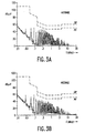
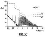
- the level (in dB ⁇ V) of the conducted interference, measured in the lighting units "inv1", “inv2” and “ref”, as a function of the frequency (in MHz) is successively shown in Figs. 3A, 3B and 3C. These measurements show that the lighting unit comprising the lampholder which is not in accordance with the invention exceeds the CISPR-15 standard for the average value in the range from 0.23 MHz to 0.72 MHz.
- the lighting unit "inv1" meets the standard throughout the range from 10 kHz to 30 MHz. An even stronger reduction of the interference is achieved by means of the lighting unit "inv2".
- Fig. 4 shows a further embodiment of the lampholder in accordance with the invention. Parts shown in said Figure which correspond to parts shown in Fig. 1 bear a reference numeral which is increased by 20.
- the discharge vessel b is accommodated in a transparent housing 28 which is provided at a first end 28a with contacts 21, 21' which are constructed as contact pins which are accessible from without.
- the lampholder 20 is provided with further contacts 29, 29', which are constructed as contact sockets which are accessible from without.
- the further contacts 29, 29' are connected to the contacts 21, 21' for connecting a high-frequency power supply, via the conductor 23' which extends to the second terminal 22' and via the compensation conductor 26.
- the contact pins 21, 21' and the contact sockets 29, 29' of the lampholder are constructed so that they cooperate with each other.
- lampholders of this construction can readily be used to form a chain by connecting contact pins of lampholders in said chain to contact sockets of the neighboring lampholder.
Landscapes
- Arrangement Of Elements, Cooling, Sealing, Or The Like Of Lighting Devices (AREA)
- Circuit Arrangements For Discharge Lamps (AREA)
- Vessels And Coating Films For Discharge Lamps (AREA)
- Fastening Of Light Sources Or Lamp Holders (AREA)
Claims (5)
- Lampenfassung (0; 10, 20), die für eine Niederdruck-Entladungslampe (a) geeignet ist, die bei hoher Frequenz arbeitet und die ein längliches, röhrenförmiges Entladungsgefäß (b) umfasst, wobei diese Lampe mit einem Elektrodenpaar (c, c') zum Aufrechterhalten einer elektrischen Entladung in dem Entladungsgefäß versehen ist, welche Lampenfassung (0; 10; 20) Kontakte (1, 1'; 11, 11'; 21, 21') zum Anschließen einer hochfrequenten Stromversorgung (4; 14) aufweist, wobei die genannten Kontakte mit einer ersten (2; 12; 22) und einer zweiten Klemme (2'; 12'; 22') zum Anschließen der Lampe elektrisch verbunden sind, wobei die genannte zweite Klemme weiter von den Kontakten entfernt ist als die erste Klemme, dadurch gekennzeichnet, dass ein zwischen der ersten (2; 12; 22) und der zweiten Klemme (2'; 12'; 22') verlaufender Kompensationsleiter (6; 16; 26) mit der genannten ersten Klemme (2; 12; 22) verbunden ist.
- Lampenfassung nach Anspruch 1, dadurch gekennzeichnet, dass mit jeder der Klemmen (12, 12') eine Metallplatte (17, 17') verbunden ist.
- Lampenfassung nach Anspruch 2, dadurch gekennzeichnet, dass die Metallplatten (17, 17') einen Reflektor bilden.
- Lampenfassung nach einem der vorhergehenden Ansprüche, dadurch gekennzeichnet, dass die Lampenfassung (20) mit weiteren, von außen zugänglichen Kontakten (29, 29') versehen ist, die mit den Kontakten (21, 21') zum Anschließen der hochfrequenten Stromversorgung verbunden sind, wobei diese weiteren Kontakte (29, 29') und die Kontakte (21, 21') an entgegengesetzten Enden (28a bzw. 28b) vorgesehen sind und so ausgeführt sind, dass sie miteinander zusammenarbeiten.
- Beleuchtungseinheit mit einer Lampenfassung (0; 10) nach einem der vorhergehenden Ansprüche und einer hochfrequenten Stromversorgung (4; 14), die mit einem Transformator (5; 15) mit einer Primär- und einer Sekundärwicklung (5a, 5b; 15a, 15b) versehen ist, wobei die Kontakte (1, 1'; 11, 11') der Lampenfassung (0; 10) mit der Sekundärwicklung (5b; 15b) des Transformators (5; 15) verbunden sind.
Priority Applications (1)
| Application Number | Priority Date | Filing Date | Title |
|---|---|---|---|
| EP97943101A EP0880796B1 (de) | 1996-11-20 | 1997-10-20 | Lampenfassung und beleuchtungseinheit mit einer lampenfassung |
Applications Claiming Priority (4)
| Application Number | Priority Date | Filing Date | Title |
|---|---|---|---|
| EP96203258 | 1996-11-20 | ||
| EP96203258 | 1996-11-20 | ||
| EP97943101A EP0880796B1 (de) | 1996-11-20 | 1997-10-20 | Lampenfassung und beleuchtungseinheit mit einer lampenfassung |
| PCT/IB1997/001296 WO1998022973A2 (en) | 1996-11-20 | 1997-10-20 | Lampholder and lighting unit comprising a lampholder |
Publications (2)
| Publication Number | Publication Date |
|---|---|
| EP0880796A2 EP0880796A2 (de) | 1998-12-02 |
| EP0880796B1 true EP0880796B1 (de) | 2004-03-17 |
Family
ID=8224603
Family Applications (1)
| Application Number | Title | Priority Date | Filing Date |
|---|---|---|---|
| EP97943101A Expired - Lifetime EP0880796B1 (de) | 1996-11-20 | 1997-10-20 | Lampenfassung und beleuchtungseinheit mit einer lampenfassung |
Country Status (7)
| Country | Link |
|---|---|
| US (1) | US6127778A (de) |
| EP (1) | EP0880796B1 (de) |
| JP (1) | JP2000504475A (de) |
| CN (1) | CN1144260C (de) |
| DE (1) | DE69728133T2 (de) |
| TW (1) | TW362233B (de) |
| WO (1) | WO1998022973A2 (de) |
Families Citing this family (2)
| Publication number | Priority date | Publication date | Assignee | Title |
|---|---|---|---|---|
| DE20301956U1 (de) * | 2003-02-07 | 2004-06-17 | Ab Skf | Vorrichtung zum Schutz eines Lagers einer Elektromaschine vor einem schädigenden Stromdurchgang |
| WO2004084256A1 (en) * | 2003-03-20 | 2004-09-30 | Koninklijke Philips Electronics N.V. | Low-pressure mercury vapor discharge lamp, and system of connected such lamps |
Family Cites Families (6)
| Publication number | Priority date | Publication date | Assignee | Title |
|---|---|---|---|---|
| US2142047A (en) * | 1935-10-29 | 1938-12-27 | Hygrade Sylvania Corp | Electric discharge lamp |
| US3995928A (en) * | 1975-01-13 | 1976-12-07 | General Electric Company | High pressure metal halide lamp with electron collector |
| KR840002365B1 (ko) * | 1979-12-17 | 1984-12-21 | 제네럴 일렉트릭 컴페니 | 전자방해가 감소된 형광등 |
| GB2074781B (en) * | 1980-03-13 | 1984-03-14 | Tokyo Shibaura Electric Co | Fluorescent lamp assemblies |
| EP0115653B1 (de) * | 1982-12-22 | 1988-11-09 | Koninklijke Philips Electronics N.V. | Entladungslampe |
| GB9405371D0 (en) * | 1994-03-18 | 1994-05-04 | Ge Lighting Ltd | Electrodeless fluorescent lamp |
-
1997
- 1997-10-20 EP EP97943101A patent/EP0880796B1/de not_active Expired - Lifetime
- 1997-10-20 CN CNB971917361A patent/CN1144260C/zh not_active Expired - Lifetime
- 1997-10-20 WO PCT/IB1997/001296 patent/WO1998022973A2/en not_active Ceased
- 1997-10-20 JP JP10523377A patent/JP2000504475A/ja not_active Withdrawn
- 1997-10-20 DE DE69728133T patent/DE69728133T2/de not_active Expired - Lifetime
- 1997-11-06 TW TW086116561A patent/TW362233B/zh not_active IP Right Cessation
- 1997-11-18 US US08/972,509 patent/US6127778A/en not_active Expired - Lifetime
Also Published As
| Publication number | Publication date |
|---|---|
| EP0880796A2 (de) | 1998-12-02 |
| CN1144260C (zh) | 2004-03-31 |
| TW362233B (en) | 1999-06-21 |
| CN1208500A (zh) | 1999-02-17 |
| US6127778A (en) | 2000-10-03 |
| WO1998022973A3 (en) | 1998-07-09 |
| DE69728133D1 (de) | 2004-04-22 |
| JP2000504475A (ja) | 2000-04-11 |
| WO1998022973A2 (en) | 1998-05-28 |
| DE69728133T2 (de) | 2005-02-10 |
Similar Documents
| Publication | Publication Date | Title |
|---|---|---|
| US4414489A (en) | Compact electric discharge lamp-and-ballast unit, and plug-in ballast module therefor | |
| CA1132185A (en) | Energy saving fluorescent lamp | |
| EP0029896B1 (de) | Kompakte fluoreszierende Lichtquelle mit metallisierten Elektroden | |
| KR20010042208A (ko) | 금속 할로겐화물 램프 | |
| US6094015A (en) | Illumination unit and liquid crystal display device | |
| US4185233A (en) | High efficiency ballast system for gaseous discharge lamps | |
| US3954316A (en) | Electrical apparatus and method for reducing power consumption of a fluorescent lamp system | |
| US4348612A (en) | Compact fluorescent lamp unit for three-way fluorescent lamp fixture | |
| EP0880796B1 (de) | Lampenfassung und beleuchtungseinheit mit einer lampenfassung | |
| CN1106681C (zh) | 无电极低压放电灯 | |
| JPH09510050A (ja) | システムワット数低減装置付き照明システム | |
| US4409521A (en) | Fluorescent lamp with reduced electromagnetic interference | |
| EP0834241B1 (de) | Schaltungsanordnung | |
| GB2066559A (en) | Fluorescent lamp with reduced electromagnetic interference | |
| TW580722B (en) | Low-pressure gas discharge lamp | |
| US5003232A (en) | Luminaire having detachable reversible holders for supporting different numbers of tubular lamps | |
| WO2008065383A1 (en) | Inverters | |
| EP0569208B1 (de) | Entladungslampenanordnung | |
| JPH0268894A (ja) | 交流電圧源から白熱電球を動作する回路装置と白熱電球 | |
| NL8304164A (nl) | Wijze van bedrijven van een hogedrukontladingslamp. | |
| EP0113855A1 (de) | Leistungsbegrenztes Deckenbeleuchtungssystem für Leuchtstofflampen | |
| US3898517A (en) | Ballast circuit | |
| JP2548595Y2 (ja) | 放電灯器具 | |
| JP3834927B2 (ja) | 放電灯点灯装置 | |
| USRE31970E (en) | High efficiency ballast system for gaseous discharge lamps |
Legal Events
| Date | Code | Title | Description |
|---|---|---|---|
| PUAI | Public reference made under article 153(3) epc to a published international application that has entered the european phase |
Free format text: ORIGINAL CODE: 0009012 |
|
| AK | Designated contracting states |
Kind code of ref document: A2 Designated state(s): DE FR GB |
|
| 17P | Request for examination filed |
Effective date: 19980820 |
|
| GRAP | Despatch of communication of intention to grant a patent |
Free format text: ORIGINAL CODE: EPIDOSNIGR1 |
|
| GRAS | Grant fee paid |
Free format text: ORIGINAL CODE: EPIDOSNIGR3 |
|
| GRAA | (expected) grant |
Free format text: ORIGINAL CODE: 0009210 |
|
| AK | Designated contracting states |
Kind code of ref document: B1 Designated state(s): DE FR GB |
|
| REG | Reference to a national code |
Ref country code: GB Ref legal event code: FG4D |
|
| REG | Reference to a national code |
Ref country code: GB Ref legal event code: 746 Effective date: 20040322 |
|
| REF | Corresponds to: |
Ref document number: 69728133 Country of ref document: DE Date of ref document: 20040422 Kind code of ref document: P |
|
| ET | Fr: translation filed | ||
| PLBE | No opposition filed within time limit |
Free format text: ORIGINAL CODE: 0009261 |
|
| STAA | Information on the status of an ep patent application or granted ep patent |
Free format text: STATUS: NO OPPOSITION FILED WITHIN TIME LIMIT |
|
| REG | Reference to a national code |
Ref country code: FR Ref legal event code: D6 |
|
| 26N | No opposition filed |
Effective date: 20041220 |
|
| PGFP | Annual fee paid to national office [announced via postgrant information from national office to epo] |
Ref country code: GB Payment date: 20051026 Year of fee payment: 9 |
|
| PGFP | Annual fee paid to national office [announced via postgrant information from national office to epo] |
Ref country code: FR Payment date: 20051027 Year of fee payment: 9 |
|
| GBPC | Gb: european patent ceased through non-payment of renewal fee |
Effective date: 20061020 |
|
| REG | Reference to a national code |
Ref country code: FR Ref legal event code: ST Effective date: 20070629 |
|
| PG25 | Lapsed in a contracting state [announced via postgrant information from national office to epo] |
Ref country code: GB Free format text: LAPSE BECAUSE OF NON-PAYMENT OF DUE FEES Effective date: 20061020 |
|
| PG25 | Lapsed in a contracting state [announced via postgrant information from national office to epo] |
Ref country code: FR Free format text: LAPSE BECAUSE OF NON-PAYMENT OF DUE FEES Effective date: 20061031 |
|
| REG | Reference to a national code |
Ref country code: DE Ref legal event code: R082 Ref document number: 69728133 Country of ref document: DE Representative=s name: MEYER, MICHAEL, DIPL.-ING., DE |
|
| REG | Reference to a national code |
Ref country code: DE Ref legal event code: R082 Ref document number: 69728133 Country of ref document: DE Representative=s name: MEISSNER BOLTE PATENTANWAELTE RECHTSANWAELTE P, DE Effective date: 20140331 Ref country code: DE Ref legal event code: R082 Ref document number: 69728133 Country of ref document: DE Representative=s name: MEYER, MICHAEL, DIPL.-ING., DE Effective date: 20140331 Ref country code: DE Ref legal event code: R081 Ref document number: 69728133 Country of ref document: DE Owner name: PHILIPS LIGHTING HOLDING B.V., NL Free format text: FORMER OWNER: KONINKLIJKE PHILIPS ELECTRONICS N.V., EINDHOVEN, NL Effective date: 20140331 Ref country code: DE Ref legal event code: R081 Ref document number: 69728133 Country of ref document: DE Owner name: KONINKLIJKE PHILIPS N.V., NL Free format text: FORMER OWNER: KONINKLIJKE PHILIPS ELECTRONICS N.V., EINDHOVEN, NL Effective date: 20140331 |
|
| REG | Reference to a national code |
Ref country code: DE Ref legal event code: R082 Ref document number: 69728133 Country of ref document: DE Representative=s name: MEISSNER BOLTE PATENTANWAELTE RECHTSANWAELTE P, DE Ref country code: DE Ref legal event code: R081 Ref document number: 69728133 Country of ref document: DE Owner name: PHILIPS LIGHTING HOLDING B.V., NL Free format text: FORMER OWNER: KONINKLIJKE PHILIPS N.V., EINDHOVEN, NL |
|
| PGFP | Annual fee paid to national office [announced via postgrant information from national office to epo] |
Ref country code: DE Payment date: 20170102 Year of fee payment: 20 |
|
| REG | Reference to a national code |
Ref country code: DE Ref legal event code: R071 Ref document number: 69728133 Country of ref document: DE |