EP0880880A2 - Selbstfahrender Rasenmäher mit Grasfangbehälter - Google Patents
Selbstfahrender Rasenmäher mit Grasfangbehälter Download PDFInfo
- Publication number
- EP0880880A2 EP0880880A2 EP98440112A EP98440112A EP0880880A2 EP 0880880 A2 EP0880880 A2 EP 0880880A2 EP 98440112 A EP98440112 A EP 98440112A EP 98440112 A EP98440112 A EP 98440112A EP 0880880 A2 EP0880880 A2 EP 0880880A2
- Authority
- EP
- European Patent Office
- Prior art keywords
- driver
- collector
- mower
- mower according
- flap
- Prior art date
- Legal status (The legal status is an assumption and is not a legal conclusion. Google has not performed a legal analysis and makes no representation as to the accuracy of the status listed.)
- Granted
Links
- 244000025254 Cannabis sativa Species 0.000 title abstract description 6
- 238000005520 cutting process Methods 0.000 claims abstract description 34
- 241001494496 Leersia Species 0.000 claims description 30
- 241001417527 Pempheridae Species 0.000 claims description 9
- 239000002699 waste material Substances 0.000 claims description 8
- 239000000463 material Substances 0.000 claims description 2
- 230000032258 transport Effects 0.000 abstract description 2
- 238000010276 construction Methods 0.000 description 8
- 239000004020 conductor Substances 0.000 description 4
- 239000000428 dust Substances 0.000 description 4
- 230000008901 benefit Effects 0.000 description 2
- 230000000903 blocking effect Effects 0.000 description 2
- 238000001914 filtration Methods 0.000 description 2
- 238000012423 maintenance Methods 0.000 description 2
- 238000010408 sweeping Methods 0.000 description 2
- 241000135309 Processus Species 0.000 description 1
- 230000004913 activation Effects 0.000 description 1
- 230000006978 adaptation Effects 0.000 description 1
- 239000000470 constituent Substances 0.000 description 1
- 230000008878 coupling Effects 0.000 description 1
- 238000010168 coupling process Methods 0.000 description 1
- 238000005859 coupling reaction Methods 0.000 description 1
- 230000009849 deactivation Effects 0.000 description 1
- 230000000694 effects Effects 0.000 description 1
- 238000000034 method Methods 0.000 description 1
- 230000004048 modification Effects 0.000 description 1
- 238000012986 modification Methods 0.000 description 1
- 230000001376 precipitating effect Effects 0.000 description 1
- 238000001556 precipitation Methods 0.000 description 1
- 230000008569 process Effects 0.000 description 1
- 230000009467 reduction Effects 0.000 description 1
- 238000006467 substitution reaction Methods 0.000 description 1
Images


Classifications
-
- A—HUMAN NECESSITIES
- A01—AGRICULTURE; FORESTRY; ANIMAL HUSBANDRY; HUNTING; TRAPPING; FISHING
- A01D—HARVESTING; MOWING
- A01D43/00—Mowers combined with apparatus performing additional operations while mowing
- A01D43/06—Mowers combined with apparatus performing additional operations while mowing with means for collecting, gathering or loading mown material
- A01D43/063—Mowers combined with apparatus performing additional operations while mowing with means for collecting, gathering or loading mown material in or into a container carried by the mower; Containers therefor
- A01D43/0635—Mowers combined with apparatus performing additional operations while mowing with means for collecting, gathering or loading mown material in or into a container carried by the mower; Containers therefor with emptying means
-
- A—HUMAN NECESSITIES
- A01—AGRICULTURE; FORESTRY; ANIMAL HUSBANDRY; HUNTING; TRAPPING; FISHING
- A01D—HARVESTING; MOWING
- A01D42/00—Mowers convertible to apparatus for purposes other than mowing; Mowers capable of performing operations other than mowing
- A01D42/06—Sweeping or cleaning lawns or other surfaces
- A01D42/08—Sweeping snow
-
- A—HUMAN NECESSITIES
- A01—AGRICULTURE; FORESTRY; ANIMAL HUSBANDRY; HUNTING; TRAPPING; FISHING
- A01D—HARVESTING; MOWING
- A01D2101/00—Lawn-mowers
-
- A—HUMAN NECESSITIES
- A01—AGRICULTURE; FORESTRY; ANIMAL HUSBANDRY; HUNTING; TRAPPING; FISHING
- A01D—HARVESTING; MOWING
- A01D34/00—Mowers; Mowing apparatus of harvesters
- A01D34/01—Mowers; Mowing apparatus of harvesters characterised by features relating to the type of cutting apparatus
- A01D34/412—Mowers; Mowing apparatus of harvesters characterised by features relating to the type of cutting apparatus having rotating cutters
- A01D34/63—Mowers; Mowing apparatus of harvesters characterised by features relating to the type of cutting apparatus having rotating cutters having cutters rotating about a vertical axis
Definitions
- the invention relates to a ride-on mower comprising a cutting device that routes the cut grass through a connecting pipe extending backwards into a cut grass collector, knowing that for its emptying.
- the manifold is pivotally mounted so that it can be clear of the connecting pipe, and a movable flap is placed in the area of the connecting duct.
- the cutting device and the collector are mostly connected by a conduit which, when the collector is placed directly at the height of the cutting device, can also be removed or integrated into the collector.
- a shutter is provided on the connecting pipe, which, when the collector is in place, is open, if although the cut grass can go from the cutting device to the collector.
- this flap closes to prevent involuntary ejection of grass cut while the cutting device is still rotating.
- the object of the invention is to improve the mower to carried conductor and in particular its collector so that the collector is easier to handle, in particular by preventing the cut grass from falling of the collector when the latter is detached from the mower with the driver carried, and making sure the collector even collects leftover cut grass remained in the connecting pipe.
- the driver mower must be worn and its collector are distinguished by reliable operation over time, while maintaining a simple, low-breakdown and advantageous construction from the point of view of cost, and in particular that they are suitable for emptying in height.
- this object is achieved by the fact that the shutter is mounted on the manifold and, to be able to disengage the latter from the link by rotating it, can be moved to a closed position ensuring closure of the collector.
- the arrangement of the flap on the collector itself can be carried out so that the flap which is mounted in the case of known constructions on the cutting device or integral with the connecting duct attached to the latter, either in revenge fixed on the collector.
- Another solution is to leave the old shutter where it is mounted and provide a second on the collector.
- the collector can then rotate or be moved at will, which is especially advantageous in the case of constructions with high drainage.
- the flap it is particularly advantageous to arrange the flap so that what, when closing, it displaces cut grass in the connecting duct to the collector.
- the connecting conduit is thus automatically cleaned and, on the other hand, its interior volume is at least in part, preferably entirely used to collect the cut grass.
- the shutter conveys cut grass particularly efficiently remained in the connecting duct to the manifold when the flap outline almost corresponds to the internal section of the connecting duct. Volume grass in the duct is then pushed into the collector over the entire width of the duct and on this occasion, possibly compacted.
- the shutter is applied in a mobile way with its free end against the connecting pipe or against the housing of the cutting device, it is possible to adjust the cutting height of the cutting device by moving relative to the collector possibly filled and therefore heavy, collector whose position it is then unnecessary to modify when adjusting the height.
- the shutter is conveniently connected to a device which, when the collector is released from the ride-on mower. automatically switches from the open position to the closed position.
- This command for moving the flap is preferably arranged on the collector and produced as a system hydraulic.
- the flap in the open position acts as a side wall, in particular back wall, connecting duct and the flap is pivotally mounted on the lower edge of the opening where the collector opens. This allows to optimally clear the duct.
- the flap acts as the bottom of the connecting duct
- it should go up towards the rear of the cutting device towards the collector. This routes the cut grass up into the conduit, so that it penetrates as high as possible in the collector and thus allows optimal filling of it.
- the implementation of the construction according to the invention is particularly recommended for ride-on mowers with a emptying device at height. Closing the collector by means of the flap allows great variability in the sequence of movements of the collector during emptying. This is particularly true also when on this occasion pivotal movements occur, which are due to lever arms in parallelogram fitted with cylinders.
- the framework part presents opportunely an assembly part for the end of the connecting duct which is associated therewith.
- the rear part is mainly made of a breathable material to guarantee the evacuation of the air transported with the cut grass.
- An alternative to the arrangement on the collector consists, in the part of the invention, to mount the flap naturally on the connecting pipe or on a part of it when the connecting pipe or said part of it follows the movement of the collector during emptying.
- the connecting duct forms then strictly speaking part of the collector.
- the mower can be furthermore provided with a front coupling for mounting auxiliary tools, such as a sweeper, snow blower or front blade, whose movements operation and / or activation and deactivation are controlled by the driver by through centralized control and are provided by means mechanical, hydraulic or pneumatic connected to the central device pneumatic or hydraulic distribution or mechanical control. So, he is possible to realize a versatile machine also finding its application in other areas of maintenance of large spaces. so that its hourly operating cost can be significantly reduced.
- auxiliary tools such as a sweeper, snow blower or front blade
- the latter When using a rotary brush sweeper driven by a hydraulic or pneumatic motor, the latter can advantageously be equipped with a means of suctioning swept waste consisting of a turbine, also hydraulically driven or pneumatically. sucking said waste directly into the sweeping enclosure and propelling them through a connecting conduit in the manifold.
- a filtering means and dust precipitation in the form of a plate filter or centrifugal.
- the column the mower's steering system may be provided with tilt adjustment means and in height of the steering column.
- tilt adjustment means and in height of the steering column.
- the means of adjusting the tilt of the steering column is advantageously in the form of a circular sector provided with a fixed post inside of the covering of said steering column, on a chassis element of the mower, and cooperating with a clamping device integral with the covering and actuated by a lever or the like mounted on the outside of the covering, the latter and the steering column being mounted on the chassis with the possibility of pivoting in a vertical plane of longitudinal axis.
- the height adjustment means of the steering column is preferably constituted by a pinching blocking device provided on a guide sleeve for a sliding upper element of the column steering, said device being actuated by means of a lever maneuver provided on the trim of the steering column.
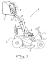
- FIG. 1 we see a mower with a carried driver 1 which is driven by a motor 2 and which passes with its wheels 3 on the ground to be mowed. She has a seat 4 on which the driver sits during mowing for operate the ride-on mower. Under driver's seat 4 is located the cutting device 5 which has two blades rotating in opposite directions and arranged side by side in the direction of travel. The direction of rotation of the blades rotatable is such that they rotate forward on the sides of the cutting device, while they turn backwards in the middle. This routes the cut grass gripped by the cutting device towards the rear, in a connecting duct 6, then this in a collector 7 which is mounted on the rear of the driver mower worn 1.
- the connecting duct 6 extends between the cutting device 5 and the manifold 7, approximately in the space between the rear wheels 3. knowing that in width, it does not exceed these and that its longitudinal extent roughly corresponds to their diameter. It is located under the engine 2 placed behind the driver's seat 4.
- the rear wheel axle can pass through the connecting duct 6. Instead, the rear wheels can be mounted in overhang on a gantry which extends outside the connecting duct, or be mounted on the frame of the mower, knowing that the wheel drive can be provided by independent hydraulic motors.
- the bottom of the connecting duct 6 is formed during mowing by a flap 8 whose rear end is fixed to the manifold 7 so as to be able to pivot about a horizontal axis 8a.
- the shutter extends in the direction of advance between the frame of the cutting device 5 and the collector 7 and in the transverse direction, over the entire width of the connecting duct 6. Sound front end is applied movably against the cutting device 5 or against its frame, so that its position on it can be changed in case of adjusting the cutting height of the cutting device 5.
- the flap 8 forming the bottom of the connecting duct 6 extends, while like its top, from the cutting device 5 upwards, towards the collector 7. This ensures that the cut grass penetrates as high as possible into the collector 7, so that there is no reason to fear a jam.
- the flap 8 according to the invention may however have a fold down in its rear part and thus, on the one hand, enlarge the capacity of the entire collecting device and, on the other hand, prevent the cut grass from slide behind the collector 7 towards the cutting device 5, even when the cutting device is not working.
- the curve bent down in the part rear of flap 8 is possible because, to release the manifold 7 from the duct link 6, the flap is folded in the direction of the latter. Indeed, it allows ensure that cut grass collected in the back of the connecting pipe 6 is pushed into the collector 7.
- Figure 2 shows the pivoting of the flap 8 around its axis horizontal which is located on the lower edge of the manifold 7 which faces the connecting duct 6.
- the connecting conduit 6 is open downwards when the flap 8 is in the closed position.
- FIG. 2 shows that the flap 8 has a hook 8b. and this, conveniently opposite its pivot axis 8a.
- This hook keeps the collector 7 in closed position during operation of the mower, while that, when the flap pivots upwards, it does not release this locking preferably that at the end of the pivoting, so that the collector can open and be emptied, which will be described later in relation to FIG. 4.
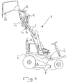
- the manifold 7 has pivoted upwards by means of a emptying device in height formed by parallelogram lever arms 9 and cylinders 10.
- the shutter 8 effectively prevents the cut grass from falling from the collector 7, even when this is released from the connecting duct 6.
- the flap 8 is closely applied against the edges of the opening of the collector 7 which connected the latter to the conduit 6. Now, when it is lifted, the collector 7 is always behind the rest of mower with operator carried 1, however no longer slightly above off the ground, but at a level above the driver's seat 4.
- the collector 7 is shown in the open state. For open it, rotate its rear part 7b 90 ° relative to the fixed frame 7a. about a horizontal axis extending transversely to the direction of advance of the mower with driver 1 and located on top of the collector, the occasion of which the collector opens on the whole section. This is done using a jack 7c which is also located on top of the manifold. However the flap 8 remains in the closed position. Of course, it would also be possible to empty the collector by opening this flap and rotating it the entire manifold 7.
- the shutter according to the invention can very advantageously serve as a means for opening the connecting duct.
- FIG. 5 of the accompanying drawings shows the adaptation, in part front of the mower, a front hitch 11 for mounting auxiliary tools 12, such as than a sweeper, snow blower or front blade.
- the annex tool 12 is in the form of a sweeper, of which maneuvering and / or switching on and off movements are controlled by the driver via a centralized control and are insured by mechanical, hydraulic, pneumatic or mechanical means 13 connected, if necessary, to the central pneumatic distribution device or mower hydraulics or mechanical control.
- a sweeper 12 can be provided, as shown in Figure 5, a bin 14 for receiving waste projected by its rotating brush 15.
- the front hitch 11 allows the mower to be transformed into a versatile machine that can be used for other maintenance tasks large areas, even outside mowing periods, i.e. for sweeping or still to clear snow in alleys, even on small roads. It results in the profitability of the mower, in terms of annual operating time. is significantly improved.
- Figure 5 of the accompanying drawings shows another characteristic of the invention, according to which the steering column 18 of the mower can be provided with means 19 and 20 for adjusting inclination and height of the steering column.
- Figure 5 shows the column of steering 18 in its two extreme pivoting positions and the steering wheel in its two extreme height adjustment positions.
- the means 19 for adjusting the inclination of the steering column 18 may be in the form of a circular sector, not shown, provided at a fixed post at the interior of the covering 21 of said steering column 18, on an element of frame of the mower, and cooperating with a clamping device integral with the covering 21 and actuated by a lever 22 or the like mounted on the outside of the covering 21.
- the latter and the steering column 18 being mounted on the chassis with possibility of pivoting in a vertical plane of longitudinal axis. So. the steering column 18, with its covering 21, can be pivoted between the extreme positions shown in Figure 5 and be stuck in that best match the driver.
- the means 20 for adjusting the height of the steering column 18 is preferably constituted by a pinching blocking device (not shown) provided on a guide sleeve of a sliding upper element of the steering column, said device being actuated by means of a operating lever 23 provided on the covering 21 of the steering column 18.
- the means 19 and 20 for adjusting the inclination and the height of the steering column 18 and their constituent parts are not shown in detail in FIG. 5 and are not the subject of a detailed description, their principles of operation and realization being perfectly and easily accessible to those skilled in the art.
- the invention it is possible to make a lawn mower with carried conductor making it possible to satisfy emptying conditions of the collector difficult, namely directly in receptacles with a high loading threshold, and whose field of use can be extended beyond simple mowing, by setting using additional tools.
Landscapes
- Life Sciences & Earth Sciences (AREA)
- Environmental Sciences (AREA)
- Harvester Elements (AREA)
- Accessories And Tools For Shearing Machines (AREA)
Applications Claiming Priority (4)
| Application Number | Priority Date | Filing Date | Title |
|---|---|---|---|
| FR9706722A FR2763783B1 (fr) | 1997-05-28 | 1997-05-28 | Tondeuse a conducteur porte comprenant notamment un collecteur pour l'herbe coupee |
| FR9706722 | 1997-05-28 | ||
| FR9710920 | 1997-08-29 | ||
| FR9710920A FR2763784B1 (fr) | 1997-05-28 | 1997-08-29 | Tondeuse a gazon a conducteur porte comprenant notamment un collecteur pour l'herbe coupee |
Publications (3)
| Publication Number | Publication Date |
|---|---|
| EP0880880A2 true EP0880880A2 (de) | 1998-12-02 |
| EP0880880A3 EP0880880A3 (de) | 1999-06-09 |
| EP0880880B1 EP0880880B1 (de) | 2002-07-31 |
Family
ID=26233574
Family Applications (1)
| Application Number | Title | Priority Date | Filing Date |
|---|---|---|---|
| EP98440112A Expired - Lifetime EP0880880B1 (de) | 1997-05-28 | 1998-05-27 | Selbstfahrender Rasenmäher mit Grasfangbehälter |
Country Status (9)
| Country | Link |
|---|---|
| US (1) | US6050072A (de) |
| EP (1) | EP0880880B1 (de) |
| AT (1) | ATE221306T1 (de) |
| CA (1) | CA2238801C (de) |
| DE (2) | DE69806851T2 (de) |
| DK (1) | DK0880880T3 (de) |
| ES (1) | ES2127176T3 (de) |
| FR (1) | FR2763784B1 (de) |
| PT (1) | PT880880E (de) |
Cited By (1)
| Publication number | Priority date | Publication date | Assignee | Title |
|---|---|---|---|---|
| CN102518060A (zh) * | 2011-12-09 | 2012-06-27 | 淮安市先锋环保设备有限公司 | 滚扫式电动清扫机械液压自卸机构 |
Families Citing this family (27)
| Publication number | Priority date | Publication date | Assignee | Title |
|---|---|---|---|---|
| JP3628231B2 (ja) * | 2000-03-30 | 2005-03-09 | 株式会社クボタ | 草刈り機 |
| JP3534687B2 (ja) * | 2000-09-19 | 2004-06-07 | 株式会社クボタ | 草刈り機 |
| JP3827959B2 (ja) * | 2001-02-13 | 2006-09-27 | 株式会社クボタ | 草刈り機 |
| US6595737B1 (en) | 2001-10-31 | 2003-07-22 | Frank Parish | Dischargeable hopper system for vehicular apparatus |
| JP3741643B2 (ja) | 2001-12-04 | 2006-02-01 | 株式会社クボタ | 草刈機の集草容器取り付け構造 |
| JP3683226B2 (ja) | 2002-03-27 | 2005-08-17 | 株式会社クボタ | 草刈機の集草案内構造 |
| US6694716B1 (en) | 2002-07-30 | 2004-02-24 | Honda Motor Co., Ltd. | Mowing machine chute cleaner apparatus and method |
| JP3776071B2 (ja) * | 2002-09-26 | 2006-05-17 | 株式会社クボタ | 集草装置及びこの集草装置を備えた草刈機 |
| JP4101159B2 (ja) * | 2003-11-21 | 2008-06-18 | 株式会社クボタ | 集草装置 |
| DE102004023994A1 (de) * | 2004-05-14 | 2005-12-01 | John Deere Enschede B.V. | Sammelbehälter eines Fahrzeugs und Fahrzeug |
| US7617663B1 (en) * | 2005-08-12 | 2009-11-17 | Humboldt Specialty Manufacturing Co. | Grass box discharge rear panel |
| US7565790B2 (en) * | 2005-09-13 | 2009-07-28 | Kubota Corporation | Grass collector for a mower |
| JP2008029233A (ja) * | 2006-07-27 | 2008-02-14 | Yanmar Co Ltd | 芝刈機 |
| US7765782B2 (en) | 2008-04-17 | 2010-08-03 | Deere & Company | Cleanout mechanism for grass discharge and collection chute |
| JP5054611B2 (ja) * | 2008-05-14 | 2012-10-24 | 株式会社クボタ | 草刈機 |
| JP5445443B2 (ja) * | 2010-12-24 | 2014-03-19 | 井関農機株式会社 | 草刈機、及び草刈機のコレクタ取り外し方法 |
| JP2013048614A (ja) * | 2011-08-31 | 2013-03-14 | Mamiya Op Co Ltd | 刈かすの収集排出装置 |
| DE102012013983A1 (de) * | 2012-07-13 | 2014-04-30 | Matev Gmbh | Mähfahrzeug |
| US9027317B2 (en) * | 2012-08-31 | 2015-05-12 | Deere & Company | Reel mower grass catcher carrier |
| JP6162577B2 (ja) * | 2013-11-11 | 2017-07-12 | 株式会社クボタ | 乗用草刈機 |
| US9433148B2 (en) * | 2014-02-20 | 2016-09-06 | Schiller Grounds Care, Inc. | Device for collecting and releasing debris |
| US9622410B2 (en) * | 2014-03-06 | 2017-04-18 | Deere & Company | Material collection parking system |
| DE102015105587A1 (de) * | 2015-04-13 | 2016-10-13 | Alfred Kärcher Gmbh & Co. Kg | Bodenreinigungsmaschine |
| JP7038638B2 (ja) * | 2018-10-10 | 2022-03-18 | 株式会社クボタ | 乗用型草刈機 |
| CN111213485A (zh) * | 2020-02-17 | 2020-06-02 | 上海海洋大学 | 用于小面积浅水区域的遥控型小型水草收割机 |
| CN112930841B (zh) * | 2021-01-14 | 2023-01-10 | 中咨数据有限公司 | 一种高速公路养护方法 |
| CN116369036A (zh) * | 2021-12-23 | 2023-07-04 | 南京泉峰科技有限公司 | 骑乘式割草设备 |
Family Cites Families (18)
| Publication number | Priority date | Publication date | Assignee | Title |
|---|---|---|---|---|
| US3038288A (en) * | 1958-07-14 | 1962-06-12 | Yard Man Inc | Riding lawn mower |
| US3247990A (en) * | 1963-10-11 | 1966-04-26 | Elgin Sweeper Co | Hopper lock for a street sweeper |
| AU282007B2 (en) * | 1964-09-11 | 1966-03-17 | Rover Mowers Pty. Ltd | Improvements in and connected with grass catchers for rotary mowers |
| US3561282A (en) * | 1970-02-05 | 1971-02-09 | Int Harvester Co | Adjustable angle steering wheel mechanism for riding mower |
| DE2950709A1 (de) * | 1979-12-21 | 1981-06-25 | MTD Products Inc., Cleveland, Ohio | Rasenmaeher |
| FR2510860A1 (fr) * | 1981-08-05 | 1983-02-11 | Wolf Outils | Perfectionnements aux tondeuses a gazon a lames de coupe tournantes |
| US4800712A (en) * | 1982-08-04 | 1989-01-31 | Outboard Marine Corporation | Grass catcher mounting system |
| IT8323912U1 (it) * | 1983-12-20 | 1985-06-20 | Fedeli Luisa | Struttura perfezionata di macchina rasaerba rotativa a conduttore seduto |
| US4637203A (en) * | 1984-07-06 | 1987-01-20 | Luisa Fedeli | Grass shaving machine |
| GB2165735B (en) * | 1984-10-19 | 1988-04-20 | Kubota Ltd | Mounting implements on tractors |
| US4726177A (en) * | 1986-09-05 | 1988-02-23 | Outboard Marine Corporation | Safety apparatus for connecting grass collector to lawn mower discharge chute |
| FR2637450B1 (fr) * | 1988-10-06 | 1990-12-21 | Etesia Scs | Dispositif de retenue de l'herbe coupee dans le receptacle de ramassage d'une tondeuse a gazon |
| JPH034714A (ja) * | 1989-05-30 | 1991-01-10 | Iseki & Co Ltd | 収納箱の移動吊持具付き簡易開閉装置 |
| US5064458A (en) | 1990-03-07 | 1991-11-12 | Allied-Signal Inc. | Heavy duty air filter with multipurpose end seal |
| FR2672464B1 (fr) * | 1991-02-12 | 1994-06-17 | Delery Creations | Dispositif permettant d'assurer le prelevement et le stockage d'herbes ou produits similaires et vehicules equipes d'un tel dispositif. |
| DE4403353A1 (de) * | 1994-02-03 | 1995-08-10 | Wiedenmann Gmbh | Mehrzweck-Arbeitsgerät mit aufsattelbarem Transportaufbau |
| US5826416A (en) * | 1995-06-02 | 1998-10-27 | Scag Power Equipment, Inc. | Lawn mower having a dual discharge system |
| US5921073A (en) * | 1998-06-26 | 1999-07-13 | Cash; Tony R. | Grass catcher |
-
1997
- 1997-08-29 FR FR9710920A patent/FR2763784B1/fr not_active Expired - Lifetime
-
1998
- 1998-05-26 CA CA002238801A patent/CA2238801C/fr not_active Expired - Fee Related
- 1998-05-27 AT AT98440112T patent/ATE221306T1/de not_active IP Right Cessation
- 1998-05-27 EP EP98440112A patent/EP0880880B1/de not_active Expired - Lifetime
- 1998-05-27 ES ES98440112T patent/ES2127176T3/es not_active Expired - Lifetime
- 1998-05-27 DK DK98440112T patent/DK0880880T3/da active
- 1998-05-27 DE DE69806851T patent/DE69806851T2/de not_active Expired - Lifetime
- 1998-05-27 DE DE0880880T patent/DE880880T1/de active Pending
- 1998-05-27 PT PT98440112T patent/PT880880E/pt unknown
- 1998-05-28 US US09/085,002 patent/US6050072A/en not_active Expired - Fee Related
Cited By (1)
| Publication number | Priority date | Publication date | Assignee | Title |
|---|---|---|---|---|
| CN102518060A (zh) * | 2011-12-09 | 2012-06-27 | 淮安市先锋环保设备有限公司 | 滚扫式电动清扫机械液压自卸机构 |
Also Published As
| Publication number | Publication date |
|---|---|
| US6050072A (en) | 2000-04-18 |
| ES2127176T1 (es) | 1999-04-16 |
| EP0880880A3 (de) | 1999-06-09 |
| DK0880880T3 (da) | 2002-11-04 |
| DE69806851D1 (de) | 2002-09-05 |
| CA2238801C (fr) | 2007-09-11 |
| CA2238801A1 (fr) | 1998-11-28 |
| ES2127176T3 (es) | 2003-02-16 |
| DE880880T1 (de) | 1999-06-10 |
| FR2763784A1 (fr) | 1998-12-04 |
| FR2763784B1 (fr) | 2000-03-17 |
| ATE221306T1 (de) | 2002-08-15 |
| PT880880E (pt) | 2002-12-31 |
| DE69806851T2 (de) | 2003-03-20 |
| EP0880880B1 (de) | 2002-07-31 |
Similar Documents
| Publication | Publication Date | Title |
|---|---|---|
| EP0880880B1 (de) | Selbstfahrender Rasenmäher mit Grasfangbehälter | |
| FR2860386A1 (fr) | Appareil collecteur d'herbe et tondeuse le comportant | |
| FR2998129A1 (fr) | Tondeuse a gazon avec unite de collecte d'herbe | |
| FR2907310A1 (fr) | Unite de tondeuse pourvue d'un element de guidage et d'un element d'ouverture/fermeture. | |
| FR2790908A1 (fr) | Machine de tonte de gazon | |
| FR3019966A1 (fr) | Tondeuse a gazon | |
| FR2891108A1 (fr) | Machine a tondre a dechargement par l'arriere | |
| CA2370486C (fr) | Vehicule routier motorise pour la realisation de tranchees dans le sol | |
| FR2862480A1 (fr) | Systeme collecteur d'herbe ayant un conduit | |
| FR2993904A1 (fr) | Chargeur frontal | |
| FR2875676A1 (fr) | Tondeuse auto-portee | |
| FR2940004A1 (fr) | Dispositif de collecte d'herbe pour une tondeuse a gazon | |
| FR2927765A1 (fr) | Dispositif de ramassage d'herbe pour une tondeuse a gazon. | |
| FR2578380A1 (fr) | Tondeuse a gazon comprenant un recepteur d'herbe commande a basculement pour son evacuation | |
| FR2534446A1 (fr) | Tondeuse a gazon a lame tournant dans un plan parallele au terrain | |
| EP0843046B1 (de) | Vorrichtung zum Kehren und Aufnehmen von Material | |
| FR2932947A1 (fr) | Dispositif de detection de quantite d'herbe coupee pour conteneur de collecte d'herbe d'une tondeuse a gazon | |
| FR2522471A1 (fr) | Vehicule de transport de recolte a dechargement automatique | |
| FR2746253A1 (fr) | Appareil de deversement pour tondeuse a gazon | |
| FR2728136A1 (fr) | Bac de ramassage a coque de vidange pour tondeuse autoportee a support de bacs amovibles, et tondeuse comportant un tel bac | |
| FR2763783A1 (fr) | Tondeuse a conducteur porte comprenant notamment un collecteur pour l'herbe coupee | |
| FR2462090A2 (fr) | Dispositif de reception de l'herbe coupee pour tondeuse a gazon | |
| FR2623534A1 (fr) | Appareil pour le ramassage des detritus sur les sols souilles, notamment pour le nettoyage des plages | |
| EP0981942A1 (de) | Grasbehälter für Aufsitz-Rasenmäher | |
| FR2860949A1 (fr) | Tondeuse a gazon a recipient collecteur d'herbe |
Legal Events
| Date | Code | Title | Description |
|---|---|---|---|
| PUAI | Public reference made under article 153(3) epc to a published international application that has entered the european phase |
Free format text: ORIGINAL CODE: 0009012 |
|
| AK | Designated contracting states |
Kind code of ref document: A2 Designated state(s): AT BE CH DE DK ES FI FR GB GR IE IT LI LU NL PT SE |
|
| AX | Request for extension of the european patent |
Free format text: AL;LT;LV;MK;RO;SI |
|
| ITCL | It: translation for ep claims filed |
Representative=s name: STUDIO TORTA SOCIETA' SEMPLICE |
|
| GBC | Gb: translation of claims filed (gb section 78(7)/1977) | ||
| TCNL | Nl: translation of patent claims filed | ||
| REG | Reference to a national code |
Ref country code: ES Ref legal event code: BA2A Ref document number: 2127176 Country of ref document: ES Kind code of ref document: T1 |
|
| PUAL | Search report despatched |
Free format text: ORIGINAL CODE: 0009013 |
|
| AK | Designated contracting states |
Kind code of ref document: A3 Designated state(s): AT BE CH CY DE DK ES FI FR GB GR IE IT LI LU MC NL PT SE |
|
| AX | Request for extension of the european patent |
Free format text: AL;LT;LV;MK;RO;SI |
|
| DET | De: translation of patent claims | ||
| 17P | Request for examination filed |
Effective date: 19990602 |
|
| AKX | Designation fees paid |
Free format text: AT BE CH DE DK ES FI FR GB GR IE IT LI LU NL PT SE |
|
| 17Q | First examination report despatched |
Effective date: 20011122 |
|
| GRAG | Despatch of communication of intention to grant |
Free format text: ORIGINAL CODE: EPIDOS AGRA |
|
| GRAG | Despatch of communication of intention to grant |
Free format text: ORIGINAL CODE: EPIDOS AGRA |
|
| GRAH | Despatch of communication of intention to grant a patent |
Free format text: ORIGINAL CODE: EPIDOS IGRA |
|
| GRAH | Despatch of communication of intention to grant a patent |
Free format text: ORIGINAL CODE: EPIDOS IGRA |
|
| GRAA | (expected) grant |
Free format text: ORIGINAL CODE: 0009210 |
|
| AK | Designated contracting states |
Kind code of ref document: B1 Designated state(s): AT BE CH DE DK ES FI FR GB GR IE IT LI LU NL PT SE |
|
| PG25 | Lapsed in a contracting state [announced via postgrant information from national office to epo] |
Ref country code: GR Free format text: LAPSE BECAUSE OF FAILURE TO SUBMIT A TRANSLATION OF THE DESCRIPTION OR TO PAY THE FEE WITHIN THE PRESCRIBED TIME-LIMIT Effective date: 20020731 Ref country code: FI Free format text: LAPSE BECAUSE OF FAILURE TO SUBMIT A TRANSLATION OF THE DESCRIPTION OR TO PAY THE FEE WITHIN THE PRESCRIBED TIME-LIMIT Effective date: 20020731 |
|
| REF | Corresponds to: |
Ref document number: 221306 Country of ref document: AT Date of ref document: 20020815 Kind code of ref document: T |
|
| REG | Reference to a national code |
Ref country code: GB Ref legal event code: FG4D Free format text: NOT ENGLISH Ref country code: CH Ref legal event code: EP |
|
| RIC1 | Information provided on ipc code assigned before grant |
Free format text: 7A 01D 34/71 A, 7A 01D 34/64 B, 7A 01D 43/06 B |
|
| REG | Reference to a national code |
Ref country code: IE Ref legal event code: FG4D Free format text: FRENCH |
|
| REF | Corresponds to: |
Ref document number: 69806851 Country of ref document: DE Date of ref document: 20020905 |
|
| REG | Reference to a national code |
Ref country code: CH Ref legal event code: NV Representative=s name: WERNER FENNER PATENTANWALT |
|
| GBT | Gb: translation of ep patent filed (gb section 77(6)(a)/1977) |
Effective date: 20021030 |
|
| REG | Reference to a national code |
Ref country code: PT Ref legal event code: SC4A Free format text: AVAILABILITY OF NATIONAL TRANSLATION Effective date: 20021028 |
|
| REG | Reference to a national code |
Ref country code: ES Ref legal event code: FG2A Ref document number: 2127176 Country of ref document: ES Kind code of ref document: T3 |
|
| PLBE | No opposition filed within time limit |
Free format text: ORIGINAL CODE: 0009261 |
|
| STAA | Information on the status of an ep patent application or granted ep patent |
Free format text: STATUS: NO OPPOSITION FILED WITHIN TIME LIMIT |
|
| 26N | No opposition filed |
Effective date: 20030506 |
|
| PGFP | Annual fee paid to national office [announced via postgrant information from national office to epo] |
Ref country code: PT Payment date: 20050505 Year of fee payment: 8 |
|
| PGFP | Annual fee paid to national office [announced via postgrant information from national office to epo] |
Ref country code: NL Payment date: 20050513 Year of fee payment: 8 Ref country code: IE Payment date: 20050513 Year of fee payment: 8 |
|
| PGFP | Annual fee paid to national office [announced via postgrant information from national office to epo] |
Ref country code: AT Payment date: 20050518 Year of fee payment: 8 |
|
| PGFP | Annual fee paid to national office [announced via postgrant information from national office to epo] |
Ref country code: ES Payment date: 20050519 Year of fee payment: 8 |
|
| PGFP | Annual fee paid to national office [announced via postgrant information from national office to epo] |
Ref country code: DK Payment date: 20050520 Year of fee payment: 8 |
|
| PGFP | Annual fee paid to national office [announced via postgrant information from national office to epo] |
Ref country code: BE Payment date: 20050530 Year of fee payment: 8 |
|
| PGFP | Annual fee paid to national office [announced via postgrant information from national office to epo] |
Ref country code: LU Payment date: 20050610 Year of fee payment: 8 |
|
| PGFP | Annual fee paid to national office [announced via postgrant information from national office to epo] |
Ref country code: CH Payment date: 20050826 Year of fee payment: 8 |
|
| PG25 | Lapsed in a contracting state [announced via postgrant information from national office to epo] |
Ref country code: AT Free format text: LAPSE BECAUSE OF NON-PAYMENT OF DUE FEES Effective date: 20060527 |
|
| PG25 | Lapsed in a contracting state [announced via postgrant information from national office to epo] |
Ref country code: IE Free format text: LAPSE BECAUSE OF NON-PAYMENT OF DUE FEES Effective date: 20060529 Ref country code: ES Free format text: LAPSE BECAUSE OF NON-PAYMENT OF DUE FEES Effective date: 20060529 |
|
| PG25 | Lapsed in a contracting state [announced via postgrant information from national office to epo] |
Ref country code: LI Free format text: LAPSE BECAUSE OF NON-PAYMENT OF DUE FEES Effective date: 20060531 Ref country code: DK Free format text: LAPSE BECAUSE OF NON-PAYMENT OF DUE FEES Effective date: 20060531 Ref country code: CH Free format text: LAPSE BECAUSE OF NON-PAYMENT OF DUE FEES Effective date: 20060531 Ref country code: BE Free format text: LAPSE BECAUSE OF NON-PAYMENT OF DUE FEES Effective date: 20060531 |
|
| PG25 | Lapsed in a contracting state [announced via postgrant information from national office to epo] |
Ref country code: PT Free format text: LAPSE BECAUSE OF NON-PAYMENT OF DUE FEES Effective date: 20061127 |
|
| PG25 | Lapsed in a contracting state [announced via postgrant information from national office to epo] |
Ref country code: NL Free format text: LAPSE BECAUSE OF NON-PAYMENT OF DUE FEES Effective date: 20061201 |
|
| REG | Reference to a national code |
Ref country code: CH Ref legal event code: PL Ref country code: DK Ref legal event code: EBP |
|
| REG | Reference to a national code |
Ref country code: PT Ref legal event code: MM4A Free format text: LAPSE DUE TO NON-PAYMENT OF FEES Effective date: 20061127 |
|
| NLV4 | Nl: lapsed or anulled due to non-payment of the annual fee |
Effective date: 20061201 |
|
| REG | Reference to a national code |
Ref country code: IE Ref legal event code: MM4A |
|
| REG | Reference to a national code |
Ref country code: ES Ref legal event code: FD2A Effective date: 20060529 |
|
| BERE | Be: lapsed |
Owner name: *ETESIA S.A.R.L. Effective date: 20060531 |
|
| PG25 | Lapsed in a contracting state [announced via postgrant information from national office to epo] |
Ref country code: LU Free format text: LAPSE BECAUSE OF NON-PAYMENT OF DUE FEES Effective date: 20060527 |
|
| PGFP | Annual fee paid to national office [announced via postgrant information from national office to epo] |
Ref country code: SE Payment date: 20130527 Year of fee payment: 16 |
|
| PGFP | Annual fee paid to national office [announced via postgrant information from national office to epo] |
Ref country code: IT Payment date: 20130522 Year of fee payment: 16 |
|
| PGFP | Annual fee paid to national office [announced via postgrant information from national office to epo] |
Ref country code: GB Payment date: 20140516 Year of fee payment: 17 |
|
| PGFP | Annual fee paid to national office [announced via postgrant information from national office to epo] |
Ref country code: DE Payment date: 20140519 Year of fee payment: 17 |
|
| PG25 | Lapsed in a contracting state [announced via postgrant information from national office to epo] |
Ref country code: SE Free format text: LAPSE BECAUSE OF NON-PAYMENT OF DUE FEES Effective date: 20140528 |
|
| REG | Reference to a national code |
Ref country code: SE Ref legal event code: EUG |
|
| PG25 | Lapsed in a contracting state [announced via postgrant information from national office to epo] |
Ref country code: IT Free format text: LAPSE BECAUSE OF NON-PAYMENT OF DUE FEES Effective date: 20140527 |
|
| REG | Reference to a national code |
Ref country code: DE Ref legal event code: R119 Ref document number: 69806851 Country of ref document: DE |
|
| GBPC | Gb: european patent ceased through non-payment of renewal fee |
Effective date: 20150527 |
|
| PG25 | Lapsed in a contracting state [announced via postgrant information from national office to epo] |
Ref country code: GB Free format text: LAPSE BECAUSE OF NON-PAYMENT OF DUE FEES Effective date: 20150527 Ref country code: DE Free format text: LAPSE BECAUSE OF NON-PAYMENT OF DUE FEES Effective date: 20151201 |
|
| REG | Reference to a national code |
Ref country code: FR Ref legal event code: PLFP Year of fee payment: 19 |
|
| REG | Reference to a national code |
Ref country code: FR Ref legal event code: PLFP Year of fee payment: 20 |
|
| PGFP | Annual fee paid to national office [announced via postgrant information from national office to epo] |
Ref country code: FR Payment date: 20170512 Year of fee payment: 20 |