EP0880914B1 - Cantine ou similaire, notamment à articulation perfectionnée - Google Patents
Cantine ou similaire, notamment à articulation perfectionnée Download PDFInfo
- Publication number
- EP0880914B1 EP0880914B1 EP98401062A EP98401062A EP0880914B1 EP 0880914 B1 EP0880914 B1 EP 0880914B1 EP 98401062 A EP98401062 A EP 98401062A EP 98401062 A EP98401062 A EP 98401062A EP 0880914 B1 EP0880914 B1 EP 0880914B1
- Authority
- EP
- European Patent Office
- Prior art keywords
- faces
- box
- folded
- cradle
- hinge
- Prior art date
- Legal status (The legal status is an assumption and is not a legal conclusion. Google has not performed a legal analysis and makes no representation as to the accuracy of the status listed.)
- Expired - Lifetime
Links
- 239000002184 metal Substances 0.000 claims abstract description 16
- 230000002093 peripheral effect Effects 0.000 claims abstract description 12
- 238000005452 bending Methods 0.000 claims abstract 5
- 238000003780 insertion Methods 0.000 claims description 11
- 230000037431 insertion Effects 0.000 claims description 11
- 230000002441 reversible effect Effects 0.000 claims description 9
- 230000000717 retained effect Effects 0.000 claims description 7
- 238000000034 method Methods 0.000 claims description 4
- 239000000470 constituent Substances 0.000 claims description 2
- 229910000831 Steel Inorganic materials 0.000 abstract 2
- 239000010959 steel Substances 0.000 abstract 2
- 239000011324 bead Substances 0.000 description 44
- 238000002788 crimping Methods 0.000 description 6
- 230000015572 biosynthetic process Effects 0.000 description 4
- 230000002787 reinforcement Effects 0.000 description 4
- 240000008042 Zea mays Species 0.000 description 3
- 238000003466 welding Methods 0.000 description 3
- 238000007789 sealing Methods 0.000 description 2
- 210000004027 cell Anatomy 0.000 description 1
- 230000003247 decreasing effect Effects 0.000 description 1
- 238000007373 indentation Methods 0.000 description 1
- 238000009434 installation Methods 0.000 description 1
- 230000000670 limiting effect Effects 0.000 description 1
- 230000036961 partial effect Effects 0.000 description 1
Images




Classifications
-
- A—HUMAN NECESSITIES
- A45—HAND OR TRAVELLING ARTICLES
- A45C—PURSES; LUGGAGE; HAND CARRIED BAGS
- A45C5/00—Rigid or semi-rigid luggage
- A45C5/04—Trunks; Travelling baskets
-
- B—PERFORMING OPERATIONS; TRANSPORTING
- B65—CONVEYING; PACKING; STORING; HANDLING THIN OR FILAMENTARY MATERIAL
- B65D—CONTAINERS FOR STORAGE OR TRANSPORT OF ARTICLES OR MATERIALS, e.g. BAGS, BARRELS, BOTTLES, BOXES, CANS, CARTONS, CRATES, DRUMS, JARS, TANKS, HOPPERS, FORWARDING CONTAINERS; ACCESSORIES, CLOSURES, OR FITTINGS THEREFOR; PACKAGING ELEMENTS; PACKAGES
- B65D43/00—Lids or covers for rigid or semi-rigid containers
- B65D43/14—Non-removable lids or covers
- B65D43/16—Non-removable lids or covers hinged for upward or downward movement
- B65D43/163—Non-removable lids or covers hinged for upward or downward movement the container and the lid being made separately
- B65D43/164—Non-removable lids or covers hinged for upward or downward movement the container and the lid being made separately and connected by interfitting hinge elements integrally with the container and the lid formed respectively
- B65D43/165—Non-removable lids or covers hinged for upward or downward movement the container and the lid being made separately and connected by interfitting hinge elements integrally with the container and the lid formed respectively these elements being assembled by a separate pin-like member
Definitions
- the subject of the present invention is a canteen or the like, especially with improved articulation.
- Robust small metallic parallelepiped trunks whose most frequent "overall" dimensions are around 75cm in width, 40cm in depth, and 35 cm in height, canteens, commonly performed in sheets of 0.5 mm (5 tenths of a mm) thick, are formed a parallelepipedic tank, or canteen proper, of which the upper side is open, with a rectangular cover obturation of this upper face, and of a joint, extending along the outside of the rear edge of the tank, around of which is articulated, foldable and liftable, this cover, thus retained in said bac.
- omegas are advantageously held at their support by means of a spot weld of their fixing strips to said support.
- Their two ends carry a folded tab, in lateral obturation of the rib, welded on the adjacent, perpendicular flank of said support.
- additional ribs are sometimes provided between the two omegas of the cover to reinforce the rigidity of the latter.
- the bin itself consists of a first plate of rectangular sheet folded into a "U" shape, forming a cradle, and two rectangular sheet metal plates, attached, sealing the two ends of this cradle and forming the two side faces of the tank, each carrying one of the two on the outside canteen handles, foldable and horizontal.
- the upper part of the tank is provided, for portion on each of its four front, rear and side faces, an outer peripheral bead of rectangular cross section, about 25 to 30 millimeters high, flush about 20 mm below the level of the edge of the opening of the tray, serving as a seat stop at the edge of the cover at the closing of the canteen, and constituting an armature of reinforcement under the vertical edge of the tank.
- the edge of the cover is provided, for portion on each of its four faces: front, rear and side, of a cylindrical border formed the gauge of approximately 5 mm in diameter in the base of said rim, and by which the cover rests on said bead. Continuous, this border is interrupted at each of the four corners of the edge of the cover, as well as, at the front, on the two insertion widths of the sleeves of the two legs canteen closure, each shaped to the profile of the bead, under which it is retained, the canteen being closed, and that, at the rear, opposite these insertion widths front, on two corresponding insertion widths sleeves of the hinge legs of the cover on Baccalaureat.
- each of the two tabs of canteen closure held vertically by the bead, is kept applied to said bead and against the wall from the front of the tank by a rod or through a padlock that of the two jumpers attached to this wall, which crosses the notch made for this purpose in said tab closing.
- the hinge tabs of the cover in the sleeves from which rotate, the maneuvered cover, the two rear hinges held in place rear of said border, are attached and fixed to the rear side of the tank, either by screwing on the bead portion of this rear face, either by welding on the rim of this face, located above the bead. At closing of the canteen, these legs are thus compressed between these two edges and deform the edge of the cover.
- the document GB 374050 shows and describes the mutual articulation of two articulated parts, no longer by attaching attached hinge legs thereto, but by forming such legs, bent into sleeves, directly and alternately in the edges of the two pieces, folded down then folded (fig.1 to fig.5 of said document), so as to constitute, in contrast to the sleeves through which the hinge of the joint, two ramps coming into abutment, one against the other, limit the angular travel of the two parts by alignment of these while increasing resistance when this joint is torn off (fig. 6 of said document).
- the document GB 365 757 shows and describes a whole series of joints for metal shoemakers light thin, including one (fig.3 of said document) whose parts carried by the rear border of the box housing are reported against the outer face of this border in the form of two legs thereof folded outwardly and the end edge of each of which is curved sleeve into which the hinge of the joint engages.
- these two legs are found, when the housing is closed, compressed between the edges of the container and the housing cover, in deformation of the edge of the cover, they offer resistance sufficient removal as long as it is only said light bootmakers, such as small metal cases, but totally insufficient in the case of canteens, said legs being only folded back by folding against said external face of the rear border of the tank.
- the document US 1676621 shows and describes (fig.1 and fig.2 of said document) a housing with cover lightweight easily interchangeable: by lateral sliding of the hinge of the joint, in clearance from one of its ends of the part of the joint, corresponding, scope by the rear edge of the box tray, then, after spacing rear side of the cover (fig. 2 of said document), in release of the other end of the hinge from the other part of the articulation carried by this rear edge of said tank. The a new cover is put in place by the operation reverse.
- each of the two parts of the joint carried by the rear edge of the tank is formed: a semi-cylindrical hollow, in relief inside the tank and in which the sleeve of a of the two curved legs carried by the cover, followed by a semi-cylindrical end boss made in the opposite direction, in relief on the outside of the tank and deflecting the end of the hinge towards the inside of the tank during its lateral sliding.
- a semi-cylindrical hollow in relief inside the tank and in which the sleeve of a of the two curved legs carried by the cover, followed by a semi-cylindrical end boss made in the opposite direction, in relief on the outside of the tank and deflecting the end of the hinge towards the inside of the tank during its lateral sliding.
- the object of the invention is in particular to obtain, for a canteen or similar, an improved articulation which frees itself of the aforementioned drawbacks inherent in the attached legs or improprieties of the other articulations of the prior art above.
- the invention further aims, without reducing or even increasing the robustness of the canteen which is the object, improve interior comfort, to bring it as close as possible possible and in the simplest way, that of the suitcases : first by eliminating any crevices and internal sharp edge, and, secondly, by bringing the as much as possible the interior volume of the canteen of that of a geometric parallelepiped, the most roomy.
- the bead is good, as in the first case cited, formed, in portions in the four sides of the tray, directly in the sheet by folding to the template, but the upper part of this sheet is then folded down internally, folded flat against the wall of the face considered, covering and closing the groove formed by the back of the bead, then spot welded to this wall, only by its edge, below the level of the bead.
- each two rectangular plates also formed in this way and closing off the two ends of the cradle and constituting the two side faces of the tank, is bordered by three bands folded inside at right angles, through which the plate is spot welded to the considered end of the cradle on all three sides.
- the document FR 1346341 shows and describes an automatic crimping process for the two lateral sides of a canteen on the ends of the cradle of his baccalaureate.
- This automatic crimping being carried out simultaneously along the lower edge of the lateral flank considered and over all the height of each of its two vertical edges, it cannot be implemented, as is, only if these two vertical edges, like those, corresponding, of the front and rear faces of said cradle are rectilinear, which is not the case for those of front, rear and side panels mentioned in the previous paragraph and in which, before the assembly of the side faces on the ends of the cradle, are previously formed in the template the portions of said bead, subsequently connected by stamped corners to the profile of this bead.
- this method provides, by pressure exerted by a sole on the crimping bead against the horizontal table which supports the crimped sidewall, total planning of said flank on its inside face to the tank, which rejects entirely said crimping bead outside the canteen, decreasing the interior volume which would be hers if this bead crimping partly overflowed inside the tank.
- the practice of unique notches with fold lines of the cradle does not favor enough obtaining a minimum rounding of the crimping bead level of its right angles.
- the canteen or the like according to the invention overcomes the disadvantages mentioned above.
- This canteen or the like in particular with improved articulation, comprises a parallelepipedic tank, or canteen proper, open on its upper face, consisting of a cradle obtained by folding in "U" shape from a rectangular sheet metal plate and from two lateral faces.
- the upper part of the sheet is not folded down internally, itself folded flat against the wall of this rear face and covering and closing the groove formed by the reverse of the bead portion which has been formed there, and then spot welded to this wall, only by its edge, below the level of this bead portion, only after the re-entrant right angle formed by the upper edge of this portion of bead carried by this rear face and the vertical rim thereof has previously been locally pushed back in the form of a rabbet with sheared edges, in which one of the hinges of the cover is retained, kept applied, by hand and on the other side of this rebate, in said re-entrant angle, the assembly carrying out, in whole or in part, said improved articulation of the cover on the tank.
- said improved articulation is provided with two rebates, symmetrical to each other with respect to the equidistant plane of the two lateral sides of the tank, each of these two rebates coming to be embedded in one of the two notches inserting the rear cylindrical edge of the cover, split into three portions forming, with them two and the two bent cylindrical hinges, the joint of the cover on this tray.
- said improved articulation has a large single rebate whose ends are symmetrical to each other with respect to the equidistant plane of the two lateral sides of the tank, this single rebate coming to fit into the unique insertion notch of the cylindrical rear edge of the lid, split into two portions forming, with them and the two bent cylindrical hinges, the articulation of the cover on this tank.
- said improved articulation is provided with a multitude of rebates coming to be embedded in as many insertion notches of the cylindrical border back of lid, split into as many more portions one, forming, with them and the two bent cylindrical hinges, of joined ends, the articulation of the cover on this tank.
- the canteen according to the invention 1, 1 ', 1 “comprises, in known manner, a parallelepipedic tank, or canteen proper 2, 2 ', 2 ", open on its upper face, consisting of a cradle obtained by "U” folding of a 0.5 mm rectangular sheet metal plate (5 tenths of a mm) thick, along the front face 11, the base 12 (fig.12) and the rear 13, 13 ', 13 “(fig.2, 4 to 9, 12 to 15) of said tank 2, 2 ', 2 ", and of two rectangular side faces 14, 15, of the same sheet, attached to the ends of the cradle they close, as well as a rectangular cover of the same sheet 3, 3 ', 3 "articulated at the rear of the tank 2, 2', 2", foldable to seal it.
- a parallelepipedic tank, or canteen proper 2, 2 ', 2 " open on its upper face, consisting of a cradle obtained by "U” folding of a 0.5 mm rectangular sheet metal plate (5 tenths
- Two “omega” 5 and 6 are fixed to base 12, closer together than those, 7 and 8, fixed to cover 3, 3 ', 3 ", as already explained in the preamble.
- the lateral faces 14, 15 each carry one of the two canteen handles 9, foldable and horizontal 10.
- the rim 27, 28, 29 (fig.10,11), 30,30 ', 30 ", of the cover 3, 3 ', 3 ", with a height of about 35mm is provided, for portion on each of its four front, side and rear faces, a discontinuous cylindrical border 31, 33, 35, 36, etc., which stops at each of the four corners of this edge of the cover 3, 3 ', 3 ", as well as two widths at the front insertion of the sleeves 32 and 34 of the two legs 25 and 26 of the canteen which, when it is closed, are locked on two jumpers 18, 19 fixed on the face front 11 of the tank 2, 2 ', 2 ".
- These sleeves 32 and 34 are mounted, rotary, on the front hinges 49 and 50 which connect the lateral parts 36 to the front portions
- the upper part of the tank 2, 2 ', 2 " is provided, under its upper edge, of rear portion 43 (fig. 6,10,11,12), an outer peripheral bead, of rectangular cross section, serving as reinforcement to the tray, seat stop at the edge of the lid rim 3, 3 ', 3 ", and holding two legs 25 and 26, conforming to its profile, when closing from the canteen.
- This bead is formed, by folding to the template, in portions 20, 21, 22 and 23, on all four sides front, rear and side of the tank 2, 2 ', 2 ", connected portions, along with the upper parts of these faces, by stamped corners 24 conforming to the profile of said bead.
- said improved articulation 4 is provided with two rebates 38, 40, symmetrical one on the other with respect to the plane equidistant from the two faces side 14, 15 of tray 2, each of these two rebates 38, 40 coming to be embedded in one of the two insertion notches of the rear cylindrical edge of the cover 3, split in three portions 37, 39, 41 forming, with them two 38, 40, and the two bent cylindrical hinges 51, 52, the joint 4 of the cover 3 on this tank 2.
- said improved articulation 4 ' is provided with a large single rebate 55 of which the ends are symmetrical to each other with respect to equidistant from the two lateral faces 14, 15 of the tank 2 ′, this unique rebate 55 coming to be embedded in the notch single rear cylindrical edge insertion of the cover 3 ′, split into two portions 37, 41 forming, with it 55 and the two bent cylindrical hinges 51, 52, the hinge 4 'of the cover 3' on this tank 2 '.
- said improved articulation 4 " is provided with a multitude of rebates 57 coming fit into as many notches to insert the border cylindrical rear cover 3 ", divided into as many portions 37, 56, 56, ..., 56, 56, 41 plus one, forming, with they 57 and the two bent cylindrical hinges 53, 54, of ends contiguous, the joint 4 "of the cover 3" on this 2 "tray.
- each of the two lateral faces 14, 15 of the tank 2, 2 ', 2 " being, like the front faces 11 and rear 13, 13 ', 13 “thereof, previously completed by internal folding of the upper part of its sheet, folded flat against its wall, overlapping and closing the groove formed by the reverse of its portion of bead and spot welding 46 to this wall, only by its edge below the level of the bead, and the edge of the lateral face 14, 15 projecting, below the level of the folded upper part of said lateral face 14, 15, this is fixed, according to 16 or 17 , to the cradle of the tank 2, 2 ′, 2 ", by double folding, together, of the end edge of the cradle and that of this lateral face 14, 15, under a minimum rounding of the right angle that each of the front 11 and rear 13, 13 ', 1 forms 3 "with the base 12 of the tray 2, 2 ', 2", the upper parts folded down from the four vertical faces of the tray 2, 2'
Landscapes
- Engineering & Computer Science (AREA)
- Mechanical Engineering (AREA)
- Rigid Containers With Two Or More Constituent Elements (AREA)
- Packages (AREA)
- Purses, Travelling Bags, Baskets, Or Suitcases (AREA)
- Packaging Of Annular Or Rod-Shaped Articles, Wearing Apparel, Cassettes, Or The Like (AREA)
- Road Signs Or Road Markings (AREA)
- Paints Or Removers (AREA)
Description

- d'une part, le berceau du bac, constitué par sa base et les faces avant et arrière, se prolonge, à chacune de ses deux extrémités, par une bordure d'extrémité dudit berceau, bordant chacun de ces trois éléments constitutifs mais limitée au niveau du bord des parties supérieures rabattues desdites faces avant et arrière, cette bordure d'extrémité étant entaillée de plusieurs échancrures au niveau de chacune des deux lignes de pliage du berceau ;
- d'autre part, chacune des deux faces latérales est elle-même pourvue d'une bordure périphérique, faisant latéralement saillie en dessous du niveau du bord de sa partie supérieure rabattue, et est étampée en creux, en formation d'une rampe périphérique inclinée ;
- enfin, la fixation de chacune des deux faces latérales sur l'extrémité correspondante du berceau est, préalablement à la pose des coins emboutis de raccordement des parties supérieures rabattues et des portions de bourrelet des faces avant et arrière, à celles portées par la face latérale considérée, pose qui complète cette fixation, obtenue, seulement le long desdites bordures, en dessous du niveau du bord desdites parties supérieures rabattues, par double repliement, ensemble, de la bordure d'extrémité du berceau et de la bordure périphérique de la face latérale considérée, cette dernière étant repliée extérieurement, perpendiculairement au plan de cette face latérale, et venant s'engager dans la bordure d'extrémité du berceau, repliée intérieurement (1er repliement), puis par repliement de l'ensemble des deux bordures, en engagement de la bordure d'extrémité du berceau, repliée, sous la rampe inclinée de cette face latérale (2ème repliement) ; les multiples échancrures, dont est entaillée la bordure d'extrémité du berceau au niveau de chacune des deux lignes de pliage du berceau à angle droit, permettant d'obtenir une fixation par double repliement d'arrondi minimum.
- la figure 1 montre, vue de trois-quarts face en perspective cavalière, une cantine selon l'une des trois formes de réalisation ci-dessus,
- la figure 2 représente, vue de trois-quarts arrière en perspective cavalière, une cantine selon la forme préférée de réalisation de l'invention,
- la figure 3 montre, isolé mais selon l'orientation qui est la sienne à la figure 2, le gond arrière gauche de l'articulation du couvercle sur le bac de la cantine représentée à la figure 2,
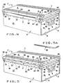
- la figure 4 représente, vue de trois-quarts arrière en perspective cavalière, une cantine selon la première variante de réalisation de l'invention,
- la figure 5 montre, vue de trois-quarts arrière en perspective cavalière, une cantine selon la deuxième variante de réalisation de l'invention,
- la figure 5A représente, isolé mais selon l'orientation qui est la sienne à la figure 5, le gond arrière gauche de l'articulation du couvercle sur le bac de la cantine montrée à la figure 5,
- la figure 6 montre, en perspective cavalière agrandie, couvercle enlevé, le coin arrière gauche du bac de la cantine, selon la forme préférée de réalisation de l'invention, représentée à la figure 2, de trois-quarts arrière,
- les figures 7, 8 et 9 montrent en section verticale les trois phases successives de formation de la face arrière de la cantine, selon la forme préférée de réalisation de l'invention représentée aux figures 1 et 2,
- les figures 10 et 11 représentent, aussi en section verticale partielle, la cantine selon la forme préférée de réalisation de l'invention, selon les lignes X - X, respectivement XI - XI de la figure 2.
- la figure 12 montre, en perspective cavalière agrandie, couvercle enlevé, le coin arrière droit, vu de l'intérieur, de la cantine, selon la forme préférée de réalisation de l'invention montrée aux figures 1 et 2,
- la figure 13 est une coupe selon la ligne XIII - XIII de la figure 12,
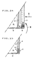
- les figures 14 et 15 montrent en sections verticales, les deux phases successives de la fixation de la face latérale droite de la cantine, par double repliement, sur l'extrémité droite du berceau de cette cantine.
Claims (5)
- Cantine, notamment à articulation perfectionnée, comprenant un bac parallèlépipédique (2,2',2"), ouvert sur sa face supérieure, constitué d'un berceau obtenu par pliage en "U" d'une plaque de tôle rectangulaire et de deux faces latérales rectangulaires (14,15) en tôle, rapportées et obturant les deux extrémités du berceau, ainsi qu'un couvercle rectangulaire (3,3',3") rabattable en obturation du bac (2,2',2") autour de son articulation audit bac, s'étendant le long extérieur du rebord arrière de celui-ci; la partie supérieure dudit bac (2,2',2") étant pourvue, situé sous son rebord supérieur vertical, d'un bourrelet périphérique extérieur de section droite rectangulaire, servant de butée d'assise au rebord (27,28,29,30,30',30") du couvercle (3,3',3") à la fermeture de la cantine, bourrelet formé, par portions (20,21,21',21",22) dans les quatre faces avant (11), arrière (13,13',13") et latérales (14,15) du bac (2,2',2"), directement dans la tôle par pliage au gabarit, et la partie supérieure de cette tôle étant ensuite, sur la face avant (11) et les deux faces latérales (14,15) du bac (2,2',2"), directement rabattue intérieurement, repliée à plat contre la paroi de cette face avant (11), respectivement de ces faces latérales (14,15) et recouvrant et obturant la rainure formée par l'envers du bourrelet, puis soudée par points (46) à cette paroi, seulement par son bord, au dessous du niveau du bourrelet, caractérisée en ce que, sur la face arrière (13,13',13") du bac (2,2',2"), d'une part, la partie supérieure (Q) de la tôle est rabattue intérieurement, elle-même repliée à plat (45) contre la paroi de cette face arrière (13,13',13") et recouvrant et obturant la rainure formée par l'envers de la portion (21,21',21") de bourrelet qui y a été formée, puis soudée par points (46) à cette paroi, seulement par son bord, au dessous du niveau de cette portion (21,21',21") de bourrelet; et, d'autre part, l'angle droit rentrant formé par le bord supérieur (58) de cette portion (21,21',21") de bourrelet portée par cette face arrière (13,13',13") et le rebord vertical (43) de celle-ci est, préalablement au rabattement susvisé de la partie supérieure (Q) de la tôle, localement repoussé en saillie et forme une feuillure (38,40,55,57) à bords cisaillés, dans laquelle l'un des gonds (51,52,53,54) du couvercle (3,3',3") est retenu, maintenu appliqué, de part et d'autre de cette feuillure (38,40,55,57), dans ledit angle rentrant, l'ensemble réalisant, en totalité ou en partie, ladite articulation perfectionnée (4,4',4") du couvercle (3,3',3") sur le bac (2,2',2").
- Cantine selon la revendication 1, caractérisée en ce que ladite articulation perfectionnée est pourvue de deux feuillures (38, 40), symétriques l'une de l'autre par rapport au plan équidistant des deux faces latérales (14, 15) du bac, chacune de ces deux feuillures (38, 40) venant s'encastrer dans l'une des deux échancrures d'insertion de la bordure cylindrique arrière du couvercle (3), scindée en trois portions (37, 39, 41) formant , avec elles deux et les deux gonds cylindriques coudés (51, 52), l'articulation (4) du couvercle (3) sur ce bac (2).
- Cantine selon la revendication 1, caractérisée en ce que ladite articulation perfectionnée est pourvue d'une large feuillure unique (55) dont les extrémités sont symétriques l'une de l'autre par rapport au plan équidistant des deux faces latérales (14, 15) du bac, cette unique feuillure (55) venant s'encastrer dans l'échancrure unique d'insertion de la bordure cylindrique arrière du couvercle (3'), scindée en deux portions (37, 41) formant , avec elle et les deux gonds cylindriques coudés (51, 52), l'articulation (4') du couvercle (3') sur ce bac (2').
- Cantine selon la revendication 1, caractérisée en ce que ladite articulation perfectionnée est pourvue d'une multitude de feuillures (57) venant s'encastrer dans autant d'échancrures d'insertion de la bordure cylindrique arrière du couvercle (3"), scindée en autant de portions (37, 56, 56, ..., 56, 56, 41) plus une, formant, avec elles et les deux gonds cylindriques coudés (53, 54), d'extrémités jointives, l'articulation (4") du couvercle (3") sur ce bac (2").
- Cantine selon l'une, quelconque, des revendications précédentes, dans laquelle chacune des quatre faces verticales avant (11), arrière (13, 13', 13") et latérales (14, 15) du bac (2, 2', 2") étant préalablement terminée par rabattement intérieur de la partie supérieure de sa tôle, repliée à plat contre sa paroi, en recouvrement et obturation de la rainure formée par l'envers de sa portion de bourrelet et le soudage par points à cette paroi, seulement par son bord, au dessous du niveau du bourrelet, les parties supérieures rabattues de ces quatre faces verticales, ainsi que les quatre portions de bourrelets correspondantes, se raccordant par quatre coins emboutis (24) au profil du bourrelet et dont les deux pattes supérieures (61, 62) sont repliées sur les deux parties supérieures rabattues (45, 48) des deux faces adjacentes, caractérisée en ce que, d'une part, le berceau du bac (2, 2', 2"), constitué par sa base (12) et les faces avant (11) et arrière (13, 13', 13"), se prolonge, à chacune de ses deux extrémités, par une bordure d'extrémité dudit berceau, bordant chacun de ces trois éléments constitutifs mais limitée au niveau du bord des parties supérieures rabattues desdites faces avant (11) et arrière (13, 13', 13"), cette bordure d'extrémité étant entaillée de plusieurs échancrures (60) au niveau de chacune des deux lignes de pliage du berceau ; en ce que, d'autre part, chacune des deux faces latérales (14, 15) est elle-même pourvue d'une bordure périphérique, faisant latéralement saillie en dessous du niveau du bord de sa partie supérieure rabattue, et est étampée en creux, en formation d'une rampe périphérique inclinée (59) ; et en ce que, enfin, la fixation de chacune des deux faces latérales (14, 15) sur l'extrémité correspondante du berceau est, préalablement à la pose des coins emboutis (24) de raccordement des parties supérieures rabattues et des portions de bourrelet des faces avant (11) et arrière (13, 13', 13") à celles portées par la face latérale considérée (14 ou 15), pose qui complète cette fixation (16, 17), obtenue, seulement le long desdites bordures, en dessous du niveau du bord desdites parties supérieures rabattues, par double repliement, ensemble, de la bordure d'extrémité du berceau et de la bordure périphérique de la face latérale considérée (14 ou 15), cette dernière étant repliée extérieurement, perpendiculairement au plan de cette face latérale, et venant s'engager dans la bordure d'extrémité du berceau, repliée intérieurement (1er repliement), puis par repliement de l'ensemble des deux bordures, en engagement de la bordure d'extrémité du berceau, repliée, sous la rampe inclinée (59) de cette face latérale (2ème repliement); les multiples échancrures (60), dont est entaillée la bordure d'extrémité du berceau au niveau de chacune des deux lignes de pliage du berceau à angle droit, permettant d'obtenir une fixation (16, 17) par double repliement d'arrondi minimum.
Applications Claiming Priority (2)
| Application Number | Priority Date | Filing Date | Title |
|---|---|---|---|
| FR9705534A FR2762760B1 (fr) | 1997-05-02 | 1997-05-02 | Cantine ou similaire, notamment a articulation perfectionnee |
| FR9705534 | 1997-05-02 |
Publications (2)
| Publication Number | Publication Date |
|---|---|
| EP0880914A1 EP0880914A1 (fr) | 1998-12-02 |
| EP0880914B1 true EP0880914B1 (fr) | 2003-07-02 |
Family
ID=9506604
Family Applications (1)
| Application Number | Title | Priority Date | Filing Date |
|---|---|---|---|
| EP98401062A Expired - Lifetime EP0880914B1 (fr) | 1997-05-02 | 1998-04-30 | Cantine ou similaire, notamment à articulation perfectionnée |
Country Status (5)
| Country | Link |
|---|---|
| EP (1) | EP0880914B1 (fr) |
| AT (1) | ATE243953T1 (fr) |
| DE (1) | DE69815948T2 (fr) |
| ES (1) | ES2202768T3 (fr) |
| FR (1) | FR2762760B1 (fr) |
Family Cites Families (6)
| Publication number | Priority date | Publication date | Assignee | Title |
|---|---|---|---|---|
| US1676621A (en) * | 1922-11-06 | 1928-07-10 | American Can Co | Interchangeable-cover cracker can |
| GB365757A (en) * | 1931-01-02 | 1932-01-28 | Arthur Leslie Stuchbery | Improvements in or relating to metal tins or containers |
| GB374050A (en) * | 1931-02-21 | 1932-05-23 | Cranford Mfg Company Ltd | Improvements in hinges for motor-car bonnets and similar structures |
| FR1317819A (fr) * | 1962-03-13 | 1963-02-08 | ||
| FR1346341A (fr) * | 1962-10-31 | 1963-12-20 | Continent Steel Products Franc | Cantine métallique |
| FR2388521A1 (fr) * | 1977-04-29 | 1978-11-24 | Chaffoteaux Sa Guy | Cantine, ou similaire, a armature perfectionnee |
-
1997
- 1997-05-02 FR FR9705534A patent/FR2762760B1/fr not_active Expired - Fee Related
-
1998
- 1998-04-30 EP EP98401062A patent/EP0880914B1/fr not_active Expired - Lifetime
- 1998-04-30 DE DE69815948T patent/DE69815948T2/de not_active Expired - Lifetime
- 1998-04-30 AT AT98401062T patent/ATE243953T1/de not_active IP Right Cessation
- 1998-04-30 ES ES98401062T patent/ES2202768T3/es not_active Expired - Lifetime
Also Published As
| Publication number | Publication date |
|---|---|
| EP0880914A1 (fr) | 1998-12-02 |
| DE69815948T2 (de) | 2004-05-27 |
| ES2202768T3 (es) | 2004-04-01 |
| ATE243953T1 (de) | 2003-07-15 |
| DE69815948D1 (de) | 2003-08-07 |
| FR2762760B1 (fr) | 1999-06-18 |
| FR2762760A1 (fr) | 1998-11-06 |
Similar Documents
| Publication | Publication Date | Title |
|---|---|---|
| CA2047497C (fr) | Caisses en une matiere en feuille, flans et machine pour la realisation de telles caisses | |
| EP0149285B1 (fr) | Procédé pour la formation de boîtes à coffret, boîtes qui en résultent et éléments pour leur formation | |
| EP0876281B1 (fr) | Ensemble de decoupes, boite, procede et machine pour la fabrication de boite a partir d'un tel ensemble de decoupes | |
| WO1997010137A2 (fr) | Contenant livre a plat, puis mis en volume en deux phases distinctes, et portant de l'adhesif a effet prolonge | |
| EP0605268A1 (fr) | Emballage à section polygonale en une matière en feuille, notamment pour bouteilles, flan et machine pour un tel emballage | |
| CA2353317C (fr) | Boite en carton ou materiau analogue, a dispositif de fermeture ameliore | |
| EP0732269A1 (fr) | Flan en carton destiné à la réalisation d'une boîte de présentation d'un contenu tel qu'un flacon de produit cosmétique | |
| EP0691918A1 (fr) | Emballage de protection et de calage pour le conditionnement d'un verre de lunettes ou d'un produit de forme analogue | |
| EP0880914A1 (fr) | Cantine ou similaire, notamment à articulation perfectionnée | |
| FR2686316A1 (fr) | Emballage en carton, carton ondule ou autre materiau en feuille convenablement decoupe et plie, a couvercle refermable par encliquetage, et flan(s) correspondant(s). | |
| FR2945516A1 (fr) | Flan d'une decoupe de matiere semi-rigide pour former apres pliage un emballage et emballage ainsi obtenu. | |
| EP1186540B1 (fr) | Etui à compartiments en forme de coins | |
| FR2774973A1 (fr) | Perfectionnement pour boite presentoir | |
| CH699529B1 (fr) | Boîte de conditionnement à volet coulissant. | |
| FR2664546A1 (fr) | Cellule isotherme demontable pour fourgonnette. | |
| FR2605596A1 (fr) | Contenant a couvercle coiffant de memes dimensions que le corps et a parois extensibles | |
| EP1435309B1 (fr) | Caisse pour un véhicule industriel, procédé de fabrication d'une telle caisse et véhicule industriel comportant une telle caisse | |
| FR2618416A1 (fr) | Emballage de vente a deux compartiments | |
| EP0887275B1 (fr) | Emballage pour pièce rectangulaire et plate, telle qu'un capot de véhicule | |
| FR2668127A1 (fr) | Emballage de transport pour animaux vivants de laboratoire souris - rats - cobayes. | |
| FR2803823A1 (fr) | Conteneur a poignee incorporant des moyens de verrouillage de sa fermeture, pour recevoir un contenu pesant, disque de frein notamment | |
| FR2740112A1 (fr) | Boite avec calage integre | |
| FR2658482A1 (fr) | Emballage en carton, carton ondule ou autre materiau en feuille convenablement decoupe et plie, a couvercle equipe d'une poignee et refermable, et flan(s) correspondant(s). | |
| FR2723719A1 (fr) | Boite pliante obtenue a partir d'une piece decoupee | |
| MC1130A1 (fr) | Emballages,notamment en carton,ouverables par formation d'un volet |
Legal Events
| Date | Code | Title | Description |
|---|---|---|---|
| PUAI | Public reference made under article 153(3) epc to a published international application that has entered the european phase |
Free format text: ORIGINAL CODE: 0009012 |
|
| 17P | Request for examination filed |
Effective date: 19980522 |
|
| AK | Designated contracting states |
Kind code of ref document: A1 Designated state(s): AT BE CH CY DE DK ES FI GB GR IE IT LI LU MC NL PT SE |
|
| AX | Request for extension of the european patent |
Free format text: AL PAYMENT 980522;LT PAYMENT 980522;LV PAYMENT 980522;MK PAYMENT 980522;RO PAYMENT 980522;SI PAYMENT 980522 |
|
| AKX | Designation fees paid |
Free format text: AT BE CH CY DE DK ES FI GB GR IE IT LI LU MC NL PT SE |
|
| AXX | Extension fees paid |
Free format text: AL PAYMENT 19980522;LT PAYMENT 19980522;LV PAYMENT 19980522;MK PAYMENT 19980522;RO PAYMENT 19980522;SI PAYMENT 19980522 |
|
| 17Q | First examination report despatched |
Effective date: 20000724 |
|
| GRAG | Despatch of communication of intention to grant |
Free format text: ORIGINAL CODE: EPIDOS AGRA |
|
| GRAG | Despatch of communication of intention to grant |
Free format text: ORIGINAL CODE: EPIDOS AGRA |
|
| GRAG | Despatch of communication of intention to grant |
Free format text: ORIGINAL CODE: EPIDOS AGRA |
|
| GRAH | Despatch of communication of intention to grant a patent |
Free format text: ORIGINAL CODE: EPIDOS IGRA |
|
| GRAH | Despatch of communication of intention to grant a patent |
Free format text: ORIGINAL CODE: EPIDOS IGRA |
|
| GRAA | (expected) grant |
Free format text: ORIGINAL CODE: 0009210 |
|
| AK | Designated contracting states |
Designated state(s): AT BE CH CY DE DK ES FI GB GR IE IT LI LU MC NL PT SE |
|
| AX | Request for extension of the european patent |
Extension state: AL LT LV MK RO SI |
|
| PG25 | Lapsed in a contracting state [announced via postgrant information from national office to epo] |
Ref country code: NL Free format text: LAPSE BECAUSE OF FAILURE TO SUBMIT A TRANSLATION OF THE DESCRIPTION OR TO PAY THE FEE WITHIN THE PRESCRIBED TIME-LIMIT Effective date: 20030702 Ref country code: FI Free format text: LAPSE BECAUSE OF FAILURE TO SUBMIT A TRANSLATION OF THE DESCRIPTION OR TO PAY THE FEE WITHIN THE PRESCRIBED TIME-LIMIT Effective date: 20030702 Ref country code: CY Free format text: LAPSE BECAUSE OF FAILURE TO SUBMIT A TRANSLATION OF THE DESCRIPTION OR TO PAY THE FEE WITHIN THE PRESCRIBED TIME-LIMIT Effective date: 20030702 Ref country code: AT Free format text: LAPSE BECAUSE OF FAILURE TO SUBMIT A TRANSLATION OF THE DESCRIPTION OR TO PAY THE FEE WITHIN THE PRESCRIBED TIME-LIMIT Effective date: 20030702 |
|
| REG | Reference to a national code |
Ref country code: GB Ref legal event code: FG4D Free format text: NOT ENGLISH |
|
| REG | Reference to a national code |
Ref country code: CH Ref legal event code: EP |
|
| REG | Reference to a national code |
Ref country code: IE Ref legal event code: FG4D Free format text: FRENCH |
|
| REF | Corresponds to: |
Ref document number: 69815948 Country of ref document: DE Date of ref document: 20030807 Kind code of ref document: P |
|
| PG25 | Lapsed in a contracting state [announced via postgrant information from national office to epo] |
Ref country code: SE Free format text: LAPSE BECAUSE OF FAILURE TO SUBMIT A TRANSLATION OF THE DESCRIPTION OR TO PAY THE FEE WITHIN THE PRESCRIBED TIME-LIMIT Effective date: 20031002 Ref country code: PT Free format text: LAPSE BECAUSE OF FAILURE TO SUBMIT A TRANSLATION OF THE DESCRIPTION OR TO PAY THE FEE WITHIN THE PRESCRIBED TIME-LIMIT Effective date: 20031002 Ref country code: GR Free format text: LAPSE BECAUSE OF FAILURE TO SUBMIT A TRANSLATION OF THE DESCRIPTION OR TO PAY THE FEE WITHIN THE PRESCRIBED TIME-LIMIT Effective date: 20031002 Ref country code: DK Free format text: LAPSE BECAUSE OF FAILURE TO SUBMIT A TRANSLATION OF THE DESCRIPTION OR TO PAY THE FEE WITHIN THE PRESCRIBED TIME-LIMIT Effective date: 20031002 |
|
| GBT | Gb: translation of ep patent filed (gb section 77(6)(a)/1977) |
Effective date: 20031014 |
|
| NLV1 | Nl: lapsed or annulled due to failure to fulfill the requirements of art. 29p and 29m of the patents act | ||
| LTIE | Lt: invalidation of european patent or patent extension |
Effective date: 20030702 |
|
| REG | Reference to a national code |
Ref country code: ES Ref legal event code: FG2A Ref document number: 2202768 Country of ref document: ES Kind code of ref document: T3 |
|
| PG25 | Lapsed in a contracting state [announced via postgrant information from national office to epo] |
Ref country code: MC Free format text: LAPSE BECAUSE OF NON-PAYMENT OF DUE FEES Effective date: 20040430 Ref country code: LI Free format text: LAPSE BECAUSE OF NON-PAYMENT OF DUE FEES Effective date: 20040430 Ref country code: CH Free format text: LAPSE BECAUSE OF NON-PAYMENT OF DUE FEES Effective date: 20040430 |
|
| PLBE | No opposition filed within time limit |
Free format text: ORIGINAL CODE: 0009261 |
|
| STAA | Information on the status of an ep patent application or granted ep patent |
Free format text: STATUS: NO OPPOSITION FILED WITHIN TIME LIMIT |
|
| RAP2 | Party data changed (patent owner data changed or rights of a patent transferred) |
Owner name: PIERRE HENRY SA |
|
| 26N | No opposition filed |
Effective date: 20040405 |
|
| REG | Reference to a national code |
Ref country code: CH Ref legal event code: PL |
|
| PG25 | Lapsed in a contracting state [announced via postgrant information from national office to epo] |
Ref country code: IT Free format text: LAPSE BECAUSE OF NON-PAYMENT OF DUE FEES Effective date: 20050430 |
|
| PGFP | Annual fee paid to national office [announced via postgrant information from national office to epo] |
Ref country code: LU Payment date: 20120502 Year of fee payment: 15 Ref country code: IE Payment date: 20120502 Year of fee payment: 15 |
|
| PGFP | Annual fee paid to national office [announced via postgrant information from national office to epo] |
Ref country code: GB Payment date: 20120530 Year of fee payment: 15 Ref country code: BE Payment date: 20120529 Year of fee payment: 15 |
|
| PGFP | Annual fee paid to national office [announced via postgrant information from national office to epo] |
Ref country code: ES Payment date: 20120530 Year of fee payment: 15 Ref country code: DE Payment date: 20120918 Year of fee payment: 15 |
|
| BERE | Be: lapsed |
Owner name: S.A. GUY *CHAFFOTEAUX Effective date: 20130430 |
|
| GBPC | Gb: european patent ceased through non-payment of renewal fee |
Effective date: 20130430 |
|
| REG | Reference to a national code |
Ref country code: IE Ref legal event code: MM4A |
|
| PG25 | Lapsed in a contracting state [announced via postgrant information from national office to epo] |
Ref country code: DE Free format text: LAPSE BECAUSE OF NON-PAYMENT OF DUE FEES Effective date: 20131101 Ref country code: BE Free format text: LAPSE BECAUSE OF NON-PAYMENT OF DUE FEES Effective date: 20130430 Ref country code: GB Free format text: LAPSE BECAUSE OF NON-PAYMENT OF DUE FEES Effective date: 20130430 |
|
| REG | Reference to a national code |
Ref country code: DE Ref legal event code: R119 Ref document number: 69815948 Country of ref document: DE Effective date: 20131101 |
|
| PG25 | Lapsed in a contracting state [announced via postgrant information from national office to epo] |
Ref country code: IE Free format text: LAPSE BECAUSE OF NON-PAYMENT OF DUE FEES Effective date: 20130430 |
|
| REG | Reference to a national code |
Ref country code: ES Ref legal event code: FD2A Effective date: 20140606 |
|
| PG25 | Lapsed in a contracting state [announced via postgrant information from national office to epo] |
Ref country code: ES Free format text: LAPSE BECAUSE OF NON-PAYMENT OF DUE FEES Effective date: 20130501 |
|
| PG25 | Lapsed in a contracting state [announced via postgrant information from national office to epo] |
Ref country code: LU Free format text: LAPSE BECAUSE OF NON-PAYMENT OF DUE FEES Effective date: 20130430 |