EP0880977B1 - Arthroskopie-Kanüle mit Flüssigkeitsdichtungen - Google Patents
Arthroskopie-Kanüle mit Flüssigkeitsdichtungen Download PDFInfo
- Publication number
- EP0880977B1 EP0880977B1 EP98303654A EP98303654A EP0880977B1 EP 0880977 B1 EP0880977 B1 EP 0880977B1 EP 98303654 A EP98303654 A EP 98303654A EP 98303654 A EP98303654 A EP 98303654A EP 0880977 B1 EP0880977 B1 EP 0880977B1
- Authority
- EP
- European Patent Office
- Prior art keywords
- wall
- predetermined
- cannula
- proximal
- distal
- Prior art date
- Legal status (The legal status is an assumption and is not a legal conclusion. Google has not performed a legal analysis and makes no representation as to the accuracy of the status listed.)
- Expired - Lifetime
Links
- 239000012530 fluid Substances 0.000 title claims description 23
- 238000007789 sealing Methods 0.000 claims description 27
- 230000003014 reinforcing effect Effects 0.000 claims description 21
- 238000000034 method Methods 0.000 claims description 14
- 230000004323 axial length Effects 0.000 claims description 7
- 230000033001 locomotion Effects 0.000 claims description 5
- 230000005540 biological transmission Effects 0.000 claims 2
- 238000003780 insertion Methods 0.000 description 7
- 230000037431 insertion Effects 0.000 description 7
- 241001631457 Cannula Species 0.000 description 6
- 239000000463 material Substances 0.000 description 5
- 239000013536 elastomeric material Substances 0.000 description 3
- 238000000605 extraction Methods 0.000 description 3
- 238000004519 manufacturing process Methods 0.000 description 3
- 238000001356 surgical procedure Methods 0.000 description 3
- WYTGDNHDOZPMIW-RCBQFDQVSA-N alstonine Natural products C1=CC2=C3C=CC=CC3=NC2=C2N1C[C@H]1[C@H](C)OC=C(C(=O)OC)[C@H]1C2 WYTGDNHDOZPMIW-RCBQFDQVSA-N 0.000 description 2
- 238000012217 deletion Methods 0.000 description 2
- 230000037430 deletion Effects 0.000 description 2
- 239000012528 membrane Substances 0.000 description 2
- 230000009471 action Effects 0.000 description 1
- 239000000560 biocompatible material Substances 0.000 description 1
- 230000003247 decreasing effect Effects 0.000 description 1
- 238000013461 design Methods 0.000 description 1
- 230000001627 detrimental effect Effects 0.000 description 1
- 238000012976 endoscopic surgical procedure Methods 0.000 description 1
- 239000007789 gas Substances 0.000 description 1
- 239000007788 liquid Substances 0.000 description 1
- 230000007246 mechanism Effects 0.000 description 1
- 239000000203 mixture Substances 0.000 description 1
- 238000012986 modification Methods 0.000 description 1
- 230000004048 modification Effects 0.000 description 1
- 229920003023 plastic Polymers 0.000 description 1
- 239000004033 plastic Substances 0.000 description 1
- 229920002635 polyurethane Polymers 0.000 description 1
- 239000004814 polyurethane Substances 0.000 description 1
- 230000036316 preload Effects 0.000 description 1
- 230000004044 response Effects 0.000 description 1
- 239000013589 supplement Substances 0.000 description 1
Images



Classifications
-
- A—HUMAN NECESSITIES
- A61—MEDICAL OR VETERINARY SCIENCE; HYGIENE
- A61B—DIAGNOSIS; SURGERY; IDENTIFICATION
- A61B17/00—Surgical instruments, devices or methods
- A61B17/34—Trocars; Puncturing needles
- A61B17/3462—Trocars; Puncturing needles with means for changing the diameter or the orientation of the entrance port of the cannula, e.g. for use with different-sized instruments, reduction ports, adapter seals
-
- A—HUMAN NECESSITIES
- A61—MEDICAL OR VETERINARY SCIENCE; HYGIENE
- A61B—DIAGNOSIS; SURGERY; IDENTIFICATION
- A61B17/00—Surgical instruments, devices or methods
- A61B17/34—Trocars; Puncturing needles
- A61B17/3498—Valves therefor, e.g. flapper valves, slide valves
-
- A—HUMAN NECESSITIES
- A61—MEDICAL OR VETERINARY SCIENCE; HYGIENE
- A61B—DIAGNOSIS; SURGERY; IDENTIFICATION
- A61B17/00—Surgical instruments, devices or methods
- A61B17/34—Trocars; Puncturing needles
- A61B17/3462—Trocars; Puncturing needles with means for changing the diameter or the orientation of the entrance port of the cannula, e.g. for use with different-sized instruments, reduction ports, adapter seals
- A61B2017/3464—Trocars; Puncturing needles with means for changing the diameter or the orientation of the entrance port of the cannula, e.g. for use with different-sized instruments, reduction ports, adapter seals with means acting on inner surface of valve or seal for expanding or protecting, e.g. inner pivoting fingers
Definitions
- the invention relates to a cannula for use in arthroscopic or endoscopic surgical procedures in which the cannula permits introduction of surgical instruments into a patient and wherein the cannula must be sealed to minimize uncontrolled loss of irrigating or other fluid from the surgical work site. More particularly, the invention relates to an arthroscopic cannula having fluid seals for sealing off the work site when elongated arthroscopic instruments are inserted through the cannula as well as when no instrument is present in the cannula.
- Arthroscopic (or, more generally, endoscopic) surgical procedures enable closed surgery to be performed via portals through which a variety of elongated instruments may be passed to gain access to an internal surgical work site.
- a disposable cannula is inserted into the portal in order to provide a convenient passageway through which various instruments may pass.
- the cannula must provide a sealed passageway in order to enable instruments to be passed into and out of the cannula while maintaining a fluid seal whether or not an instrument is in the cannula passageway.
- cannula seals sealing cannulas.
- Prior art attempts at sealing have met with varying degrees of success, but improvements are desirable. Since differing considerations come into play at different times during the use of such cannulas, some prior art devices utilize two different sealing mechanisms: one optimized for sealing when no instrument is present in the cannula and another optimized for sealing while an instrument is present -- hence the term "two-stage" is sometimes used to describe such cannulas.
- the variety of instruments which must be inserted through the cannula seal includes instruments of varying sizes and configurations. While the instrument shafts are usually cylindrical, some instruments may have unusually large or sharp distal tips which may cut a seal element upon the insertion or extraction of the instrument thus making it less suitable for subsequent instruments which must be inserted during the same surgical procedure. It is desirable, therefore, to devise a sealing cannula which minimizes this problem.
- the sysytem includes a surgical cannula including shield means for protecting operating room personnel from accidental contact with the trocar's sharp tip.
- the surgical cannula also includes sealing means for reliably preventing fluids from passing through the cannula both when an instrument extends through the cannula and no instrument extends through the cannula.
- Another object of this invention is to produce a sealing cannula capable of accommodating varying degrees of misalignment during instrument insertion.
- a sealing cannula for enabling passage of elongated instruments therethrough comprising a tubular housing having an axis, an inner surface and outer surface, a distal end, a proximal end and an axially aligned tubular body extending distally from the distal end.
- a first, proximal elastomeric seal is provided on the housing, this seal comprising a first tubular wall having a proximal end, a distal end and a first transverse end wall at the proximal end.
- the first transverse end wall comprises an expandable circular aperture supported by a floating means for enabling lateral and inclined motion of the circular aperture relative to the axis when an elongated instrument is inserted through the cannula.
- the first tubular wall is secured to the housing so as to align the circular aperture along the axis and space it a certain distance from the proximal end of the housing.
- a second, distal elastomeric seal is provided in the housing, this seal comprising a second tubular wall having a proximal end, a distal end and a second transverse end wall at the distal end.
- the second transverse end wall has proximal and distal sides, a transversely oriented linear slit therethrough and is secured within the housing so as to align the slit along the axis and space it a certain distance from the circular aperture.
- a generally rectangular, primary reinforcing member is formed about the slit, and extends distally from the second transverse end wall on the distally facing side of the end wall. This reinforcing member is a racetrack-shaped, raised rib that has planar, inclined lead-in surfaces on either side of the slit to facilitate instrument insertion and removal.
- sealing a cannula to enable sealing even during misalignment of the instrument relative to the axis of the cannula comprises the steps of providing an elongated cannula body having a tubular passageway and providing at the proximal end of the body a distal seal for sealing the work site when no instrument is present in the cannula.
- the method also comprises the steps of providing a proximal seal for sealingly engaging an instrument shaft of an instrument inserted through the cannula and providing a floating means associated with this proximal seal for enabling it to move relative to the axis of the cannula to maintain engagement between the proximal seal and the instrument shaft within a predetermined range of misalignment of the axis of the instrument shaft with the axis of the cannula.
- the floating means is a relatively thin annular wall section that supports the proximal seal (e.g. an axially aligned, expandable circular aperture) at a predetermined distance from the proximal end of the cannula body.
- an arthroscopic cannula 10 comprises an elongated hollow, cylindrical body portion 12 provided with a continuous external thread 14 between its proximal end 16 and its distal end 18.
- Tubular body 12 has an interior passageway 22 aligned along an axis 24 through which elongated endoscopic instruments may pass.
- An optional fluid inlet port 26 has an interior channel 28 which communicates with the interior passageway 22 of tubular body 12 in order to provide fluid inflow to the surgical work site. It will be understood that if this port is present, the fluid flows around any instrument shaft (not shown) which extends through the passageway.
- One or more optional fenestrations 20 may be provided at the distal end of the body to vary the fluid path.
- Channel 28 is provided with an enlarged transverse recess 31 which receives a stopcock valve 200 to be described in greater detail below. It will be understood that the cannula seal invention described herein may be used without fluid inlet 26.
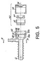
- Valve assembly 40 comprises three individual components: an elastomeric inner or distal seal 42, a rigid intermediate reinforcing and limitation member 44 and an elastomeric outer or proximal seal 46.
- the outer seal 46 When assembled, the outer seal 46 will be stretched around the cylindrical housing 30 and may, therefore, adopt a deformed shape (shown in Figures 1 and 4) in which the diameter of its proximal end is smaller than the diameter of its distal end.
- Inner seal 42 comprises an elastomeric body adapted to fit within housing chamber 32.
- inner seal 42 since the housing is cylindrical, inner seal 42 has a cylindrical body 50 having a predetermined axial length L1, an annular groove 52 adjacent its proximal end and a linear slit 54 adjacent its distal end.
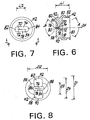
- Slit 54 has a length L2 in a direction transverse to axis 24 and is surrounded by a generally rectangular or racetrack (elongated oval) shaped primary reinforcing member 56.
- the reinforcing function of member 56 is bolstered by a pair of opposed, lateral (secondary) reinforcing members 58 and 60.
- Length L2 is relatively long in order to accommodate large diameter instrument shafts.
- distal seal 42 is molded from a biocompatible elastomeric material having a sufficient amount of flexibility, resilience and elongation range to accommodate a selected range of instrument shaft sizes (such as a range from 2.7 mm to 8.4 mm diameter).
- the overall maximum diameter D1 of body 50 is .9 inches (22.86 mm) and its longitudinal length L1 is .5 inches (12.70 mm).
- Slit length L2 may be on the order of .3 inches (7.62 mm) while dimensions D2 and D3 of member 56 may be on the order of .7 inches (17.78 mm) and .4 inches (10.16 mm), respectively.
- the slit 54 is defined by a pair of opposing linear edges 70 and 72 defined by the intersection of a pair of planar lead-in surfaces.
- edge 70 is defined at the intersection of proximal lead-in surface 74 and distal lead-in surface 76 while edge 72 is defined at the intersection of proximal lead-in surface 78 and distal lead-in surface 80.
- edges 70, 72 are centered at a point spaced .063 inches (1.59 mm) from the distal surface of reinforcing member 56 and .175 inches (4.46 mm) from the proximal surface (i.e. the bottom or floor surface 81 of interior area 83).
- edges 70, 72 may actually be joined during manufacture by a thin, frangible membrane which is then cut to form two facing surfaces having a longitudinal length (parallel to L1) on the order of .002 to .020 inches (.05 mm to .51 mm). Manufacturing tolerances may result in edges 70, 72 which (when viewed as in Figure 6) range from relative point contacts to contact between opposing flat faces.
- Proximal lead-in surfaces 74 and 78 are oriented at an angle A relative to each other while distal lead-in surfaces 76 and 80 are oriented at an angle B relative to each other. In the preferred embodiment these angles are on the order of 60° and 90°, respectively.
- proximal lead-in surfaces 74 and 78 are planar in a direction transverse to axis 24, parallel to slit 54, and are joined at their adjacent ends by opposing conical wall sections 82 and 84.
- the apex of each of these proximal conical wall sections coincides with the end of the slit adjacent a particular section so the surface of each planar section smoothly blends with the surfaces of the conical wall sections.
- Distal lead-in surfaces 76 and 78 are similarly joined at the their ends by opposing conical wall sections 86 and 88. The apex of these distal wall sections is also coincident with the ends of the slit.
- lead-in is used with respect to the proximally facing surfaces 74, 78 because these surfaces assist in positioning the tip of an instrument centrally, to facilitate its insertion through the cannula. Distally directed pressure on these surfaces (to the left in Figure 4) by an instrument will urge slit 54 to open before the slit edges 70, 72 actually touch the instrument tip. This action minimizes any tendency for the instrument to tear the slit or hang-up on insertion.
- the term “lead-in” is also applied to the distally facing surfaces 76, 80 just for symmetry.
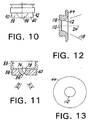
- Reinforcing member 56 has a generally quarter-circle cross-section as best seen in Figures 9 and 10.
- the quarter-circle profile is, however, modified slightly by the deletion of material necessary to form the lead-in proximal and distal surfaces and associated conical wall sections as best seen in Figure 11.
- the combination of the quarter-circle profile and material deletion produces a primary reinforcing member 56 having along its perimeter a somewhat bulbous cross-sectional appearance.
- this cross-section causes member 56 to have a thickness T along a line perpendicular to a transverse midline through surfaces 74 and 78, this thickness decreasing proximally and distally relative to this midline.
- reinforcing member 56 enhances the frictional engagement between the slit and an instrument inserted therethrough and also aids in urging the opposing slit edges 70, 72 together when there is no instrument in the cannula.
- Lateral reinforcing members 58 and 60 supplement the reinforcing action of member 56 by having outer arcuate surfaces 90 and 92, respectively, which contact the inner surface of housing 30 to further compress the edges of the slit.
- Members 58 and 60 are longitudinally coextensive with member 56. In the preferred embodiment, members 56, 58 and 60 extend distally to a point on the order of .238 inches (6.05 mm) from floor 81.
- the arcuate surfaces 90, 92 are situated at a diameter D4 which is on the order of .77 inches (19.56 mm), greater than diameter D2 so they may act on members 58 and 60 to pre-load slit 54 with a predetermined amount of closure force when no instrument is present.
- Distal seal 42 is designed to fit within the interior of housing 30 which is provided with a cylindrical wall 94, an adjacent annular groove 96 and a cylindrical proximal annular rib 98.
- Annular rib 50 and annular groove 52 of seal 42 are designed to mate, respectively, with annular groove 96 and annular rib 98 of housing 30.
- Arcuate wall sections 90 and 92 of the valve body are designed to contiguously engage opposing portions of cylindrical wall 94 in order to provide lateral resistance to reinforcing members 58 and 60.
- the proximal end 30a of housing 30 may be separately molded from the distal end 30b (which may be part of body 12).
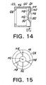
- Reinforcing and limitation member 44 has an annular body provided with a central clearance aperture 110.
- member 44 is formed from a rigid plastic material in order to fit within the interior area 83 of valve member 42 to secure it within the housing. The diameter and rigidity of member 44 are such that, when assembled as shown in Figure 4, it will cause valve member 42 to be pressed against annular rib 98.
- Member 44 serves as a size limiter, since its central aperture 110 is fixed in size and, in combination with proximal seal member 46, it also serves to limit the angle at which instruments may be inserted into the cannula.
- Annular surface 112 limits the angular deviation of an elongated instrument inserted along axis 24 to a range within which circular apertures 142 of the proximal seal 46 may move laterally without being distorted out of its circular shape. This maintains seal integrity within a range of angular deviations.
- This range may be represented by an imaginary cone having its axis aligned with axis 24 and having a conical surface 115 (not shown to scale).
- an instrument may be inserted through clearance aperture 110 anywhere within conical surface 115 without stretching aperture 142 out of shape.
- member 44 is molded from a relatively rigid biocompatible material and the diameter of central aperture 110 may be on the order of .323 inches (8.2 mm) when slit length L2 is .3 inches (7.62 mm).
- the proximally facing, annular surface 112 has a radius of curvature on the order of .188 inches (4.78 mm). This surface permits a limited amount of axial movement of the proximal outer seal 46 as will be understood below.
- the distally facing, annular surface 116 is tapered to permit the floor 81 of distal seal 42 to move axially within chamber 32 as may be necessary when an instrument is withdrawn from the cannula 10.
- Outer, proximal seal member 46 comprises an elastomeric body adapted to fit on the exterior of housing 30.
- seal 46 has a cylindrical wall 120 having a distal annular section 122 and a proximal annular section 124.
- An annular radially inwardly extending rib 126 is provided at the distal end of wall 122 and adapted to engage annular groove 128 in the exterior surface of housing 30.
- the interior surface of wall section 122 is sized to frictionally engage the exterior cylindrical surface 130 of housing 30.
- Wall section 124 has a predetermined longitudinal length L3 and supports at its proximal end a transverse end wall section 140 having an axially aligned circular aperture 142 surrounded by a flat annular transverse wall section 150.
- End wall 140 has an outer, flat annular transverse section 144 and an adjacent inner conical section 146 interposed between transverse sections 144 and 150.
- Three equilaterally spaced support ribs 148 join annular wall 124 to transverse wall section 144 and conical wall section 146.
- the function of end wall 140 is to minimize any detrimental effects of eversion and to provide a floating circular seal for preventing leakage of fluid along the shafts of elongated instruments inserted through the cannula.
- the anti-eversion feature of wall 140 facilitates maintaining the wall ready to receive an instrument. Eversion of seals engaging an instrument shaft may sometimes occur on instrument withdrawal. Thus, the frictional contact between an instrument shaft and circular aperture 142 may cause the latter to be momentarily moved to the proximal side of end wall 140 (e.g. by eversion of conical section 146). Ribs 148 would then be stretched and tend to return aperture 142 to its proper position.
- the floating feature is provided by the conical wall section 146 and by the relatively thin wall section 124 which extends a predetermined distance away from the proximal end of the cannula housing so as to space end wall 140 from the housing.
- the axial length and thinness of wall section 124 enables it to flex laterally in response to forces exerted by an instrument shaft 143 on aperture 142 and conical wall section 146.
- the sealing function of aperture 142 itself is enhanced by conical wall section 146 and by reinforcing wall section 152 which surrounds aperture 142.
- the reinforcing section 152 has a thickness greater than that of the adjacent conical wall section 146 in order to assure contact with an instrument shaft as it is inclined at an angle C.
- the conical wall section being relatively thin is able to flex to enable section 152 to be moved to a tilted or inclined position ( Figure 16b) relative to a transverse plane (i.e. the plane of aperture 142 in Figure 16a in an unbiased mode perpendicular to axis 24 with an instrument present and axially aligned).
- the proximal seal 46 is molded from a biocompatible elastomeric material similar to that used to form distal seal 42 and the overall axial length of seal member 46 is .856 inches (21.74 mm) while the length of thin section 124 is .240 inches (6.10 mm).
- the diameter of member 46 is 1.050 inches (26.67 mm) and the diameter of circular aperture 142 is .070 inches (1.78 mm).
- the thickness of distal wall section 122 may be on the order of .064 inches (1.63 mm) while that of the proximal wall section may be on the order of .020 inches (.51 mm) although these dimensions may vary given different materials. It will be understood that the proximal seal member 46 must flex a certain amount in order to achieve its intended functions. If such flexibility is not available from the choice of elastomeric materials used, then minor variations in structure may be employed, some examples of which are shown below.
- annular reinforcing wall section 152 As shown in Figures 16a and 16b, an instrument shaft inserted axially through aperture 142 will be frictionally engaged by the surrounding annular reinforcing wall section 152. As the instrument shaft is inclined relative to axis 24, as shown in Figure 16b the frictional engagement between the shaft and wall section 152 will be maintained through an angle C. Radial ribs 148 will stretch accordingly as will annular wall section 124 and conical wall section 146 in order to accommodate deflection of the instrument shaft within a certain predetermined range.
- proximal seal 46 may be made in the form of proximal seal 300 having a cylindrical serpentine wall section 302 and a conical serpentine section 304, all other portions of seal 300 being essentially the same as corresponding portions of seal 46.
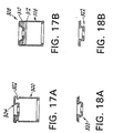
- proximal seal 306 has a ribbed cylindrical wall 308 having annular ribs 310 and grooves 312.
- Figures 18a and 18b depict two possible variations of conical wall section 146 in the form of multi-faceted conical wall section 320 and cylindrical wall section 322.
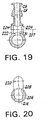
- Valve 200 used in the cannula of Figures 1-4 is best seen in Figures 1, 3, 19 and 20.
- Valve 200 comprises a valve stem 202 and a valve seat 204.
- Stem 202 is formed entirely of an elastomeric material such as polyurethane having a Shore hardness number on the order of 40-80 (A scale) and comprises a shaft 206 having an axis 207, a transverse throughbore 208 and opposing ends 210 and 212 provided with annular ribs 214 and 216 extending radially outwardly from shaft 206.
- a handle 220 is integrally formed at the proximal end of shaft 206 and extends transversely in a conventional manner to enable shaft 206 to be rotated about its axis 207.
- Valve stem 202 is sized to fit within transverse valve seat 204 which, as best seen in Figure 19, is an opening formed in transverse recess 31 and aligned along axis 207.
- Annular countersink rims 222 and 224 at the opposite ends of valve seat 204 are tapered outwardly and adapted to engage ribs 214 and 216, respectively.
- Throughbore 208 may be aligned with channel 28 or turned transversely to close the valve.
- the elastomeric nature of the valve stem 202 produces a simple valve design which enables the stopcock valve to operate efficiently with minimal complexity.
Landscapes
- Health & Medical Sciences (AREA)
- Surgery (AREA)
- Life Sciences & Earth Sciences (AREA)
- Biomedical Technology (AREA)
- Nuclear Medicine, Radiotherapy & Molecular Imaging (AREA)
- Engineering & Computer Science (AREA)
- Pathology (AREA)
- Heart & Thoracic Surgery (AREA)
- Medical Informatics (AREA)
- Molecular Biology (AREA)
- Animal Behavior & Ethology (AREA)
- General Health & Medical Sciences (AREA)
- Public Health (AREA)
- Veterinary Medicine (AREA)
- Surgical Instruments (AREA)
Claims (9)
- Abdichtende Kanüle (10) zur Bereitstellung eines Durchgangs, durch den langgestreckte Instrumente aus einem nichtfluidgefüllten Umgebungsbereich in ein fluidgefülltes Eingriffsfeld geführt werden können, während ein Abschnitt der Kanüle von dem anderen dichtend getrennt ist, mit:dadurch gekennzeichnet, daßeinem hohlen zylindrischen Gehäuse mit einer Achse, einem distalen Ende (18), einem proximalen Ende (16) und einem axial ausgerichteten röhrenförmigen Körper (12), der sich von dem distalen Ende distal erstreckt;einer proximalen ersten Dichtkappeneinrichtung (46) zur Verhinderung des Durchtritts eines Fluids aus dem Gehäuse, wenn ein Instrumentenschaft durch dieses eingeführt wird, mit:einer ersten zylindrischen elastomeren Wand (120) mit einer Achse, einem proximalen Ende und einem distalen Ende,einer ersten querliegenden Endwand (140), die das proximale Ende der ersten zylindrischen Wand schließt, wobei die Endwand eine axial ausgerichtete kreisförmige Öffnung (142) aufweist;einer Einrichtung (126) zum Beabstanden der ersten Endwand um eine vorbestimmte Längsstrecke von dem proximalen Ende des Gehäuses;einer distalen zweiten Dichtung (42) mit:einer zweiten zylindrischen Wand (50) mit einem proximalen Ende und einem distalen Ende;einer zweiten Endwand, die das distale Ende der zweiten zylindrischen Wand umschließt, wobei die zweite Endwand einen querliegenden geradlinigen Schlitz (54) aufweist;
das distale Ende der ersten zylindrischen elastomeren Wand eine erste vorbestimmte Dicke über einen vorbestimmten distalen axialen Längenabschnitt desselben hat und das proximale Ende der ersten zylindrischen elastomeren Wand eine zweite vorbestimmte Dicke über einen vorbestimmten proximalen axialen Längenabschnitt desselben hat, wobei die vorbestimmte erste Dicke größer ist als die vorbestimmte zweite Dicke; und
ein im allgemeinen rechteckiges Verstärkungsteil (56) in der zweiten Endwand um den Schlitz herum ausgebildet ist und sich um eine vorbestimmte Strecke von der zweiten Endwand auf der distal zugewandten Seite der zweiten Endwand distal erstreckt, wobei der Schlitz durch ein Paar proximal und distal zugewandte geradlinige Einführungsflächen (74, 76) begrenzt ist. - Abdichtende Kanüle nach Anspruch 1, wobei die proximal und distal zugewandten geradlinigen Einführungsflächen (74, 76) jeweils an ihren benachbarten Enden durch jeweilige konische Wandteile (82, 84) aneinandergefügt sind.
- Abdichtende Kanüle nach Anspruch 1, wobei die proximal und distal zugewandten geradlinigen Einführungsflächen (74, 76) mit Winkeln zwischen etwa 60° und 90° zueinander ausgerichtet sind.
- Abdichtende Kanüle nach Anspruch 1, wobei die Einrichtung zum Beabstanden der ersten Endwand eine Einrichtung zur Ermöglichung der Seitenbewegung aufweist, mittels der die kreisförmige Öffnung relativ zu der Achse seitlich bewegt werden kann, wobei die Einrichtung zur Ermöglichung der Seitenbewegung aufweist:einen einheitlichen zylindrischen Körper mit einem proximalen Wandteil (124) und einem distalen Wandteil (122), wobei der proximale Wandteil eine erste vorbestimmte Festigkeit hat und der distale Wandteil eine zweite vorbestimmte Festigkeit hat, wobei die erste vorbestimmte Festigkeit geringer ist als die zweite vorbestimmte Festigkeit, wobei das proximale und das distale Wandteil zur Seitenbewegung relativ zueinander geeignet sind; undeine Befestigungseinrichtung (126) zum lösbaren Befestigen des distalen Wandteils an dem Gehäuse (30), um die erste Endwand vom proximalen Ende des Gehäuses beabstandet zu halten, um eine Seitenbewegung zwischen diesen zu ermöglichen.
- Verfahren zum Abdichten einer Kanüle (10), das einen Durchgang für langgestreckte chirurgische Instrumente bereitstellt, durch den langgestreckte chirurgische Instrumente aus einem nichtfluidgefüllten Umgebungsbreich an eine fluidgefüllte chirurgische Eingriffsstelle geführt werden können, wobei das Verfahren die Schritte ausweist:dadurch gekennzeichnet, daßBereitstellen eines hohlen zylindrischen Gehäuses mit einer Achse, einem distalen Ende (18), einem proximalen Ende (16) und einem axial ausgerichteten röhrenförmigen Körper (12), der sich von dem distalen Ende distal erstreckt;Bereitstellen einer proximalen ersten Dichtkappe (46) zur Verhinderung des Durchtritts von Fluid aus dem Gehäuse, wenn ein Instrumentenschaft durch dieses eingeführt wird, wobei die Kappe (46) aufweist:eine erste zylindrische elastomere Wand (120) mit einer Achse, einem proximalen Ende und einem distalen Ende; undeine erste querliegende Endwand (140), die das proximale Ende der ersten zylindrischen Wand umschließt, wobei die Endwand eine axial ausgerichtete kreisförmige Öffnung (142) aufweist;Beabstanden der ersten Endwand um eine vorbestimmte Längenstrecke von der proximalen Wand des Gehäuses;Bereitstellen einer distalen zweiten Dichtung (42) mit:einer zweiten zylindrischen Wand (50) mit einem proximalen Ende und einem distalen Ende; undeiner zweiten Endwand, die das distale Ende der zweiten zylindrischen Wand umschließt, wobei die zweite Endwand einen querliegenden geradlinigen Schlitz (54) aufweist,
das distale Ende der ersten zylindrischen Wand eine erste vorbestimmte Dicke über einen vorbestimmten distalen Längenabschnitt derselben hat und das zweite proximale Ende der ersten zylindrischen elastomeren Wand eine zweite vorbestimmte Dicke über einen vorbestimmten proximalen axialen Längenabschnitt derselben hat, wobei die vorbestimmte erste Dicke größer ist als die vorbestimmte zweite Dicke, und durch
Ausbilden eines im allgemeinen rechteckigen Verstärkungsteils (56) in der zweiten Endwand um den Schlitz herum, das sich um eine vorbestimmte Strecke von der zweiten Endwand auf der distal zugewandten Seite der zweiten Endwand distal erstreckt, wobei der Schlitz durch ein Paar proximal und distal zugewandte geradlinige Einführungsflächen (74, 76) begrenzt ist. - Verfahren nach Anspruch 5, ferner mit dem Schritt:Bereitstellen einer Schwimmeinrichtung, die der Dichtkappe zugeordnet ist und mittels der die Dichtkappe sich relativ zur Achse der Kanüle bewegen kann, um den Eingriff zwischen der Dichtkappe und dem Instrumentenschaft in einem vorbestimmten Bereich der Fehlausrichtung der Achse des Instrumentenschafts mit der Achse der Kanüle zu halten.
- Verfahren nach Anspruch 6, wobei der Schritt des Bereitstellens einer Schwimmeinrichtung die Schritte umfaßt:Bereitstellen einer dehnbaren kreisförmigen Öffnung (142) in der Dichtkappe und Ausrichten der Achse der kreisförmigen Öffnung mit der Achse der Kanüle;Anordnen eines kreisförmigen zylindrischen Wandteils (50) mit einer vorbestimmten axialen Länge zwischen der distalen zweiten Dichtung und der Dichtkappe; undBefestigen der dehnbaren kreisförmigen Öffnung an dem kreisförmigen zylindrischen Wandteil in einer Position, die um eine vorbestimmte Strecke von dem proximalen Ende des röhrenförmigen Durchgangs beabstandet ist.
- Verfahren nach Anspruch 7, ferner mit dem Schritt:Anordnen einer Begrenzungseinrichtung (44) zwischen der distalen zweiten Dichtung und der Dichtkappe, zum Begrenzen der Winkelabweichung eines langgestreckten Instruments von der Kanülenachse bis zu einem Bereich zwischen einer ersten Richtung, die mit der Kanülenachse ausgerichtet ist, und einer zweiten Richtung, die auf der konischen Fläche eines imaginären Konus liegt, dessen Achse mit der Kanülenachse ausgerichtet ist und der einen vorbestimmten Scheitelwinkel um die Kanülenachse aufweist.
- Verfahren nach Anspruch 8, wobei die Begrenzungseinrichtung eine axial ausgerichtete Spielraumöffnung (110) zum Aufnehmen eines Instrumentenschafts aufweist, wobei die Spielraumöffnung, die von einer sich radial nach außen und proximal erstreckenden ringförmigen Fläche (112) umgeben ist, ein vorbestimmtes bogenförmiges Profil in einer axialen Ebene aufweist.
Applications Claiming Priority (2)
| Application Number | Priority Date | Filing Date | Title |
|---|---|---|---|
| US864182 | 1997-05-28 | ||
| US08/864,182 US5779697A (en) | 1997-05-28 | 1997-05-28 | Arthroscopic cannula with fluid seals |
Publications (3)
| Publication Number | Publication Date |
|---|---|
| EP0880977A2 EP0880977A2 (de) | 1998-12-02 |
| EP0880977A3 EP0880977A3 (de) | 1999-01-20 |
| EP0880977B1 true EP0880977B1 (de) | 2004-10-27 |
Family
ID=25342699
Family Applications (1)
| Application Number | Title | Priority Date | Filing Date |
|---|---|---|---|
| EP98303654A Expired - Lifetime EP0880977B1 (de) | 1997-05-28 | 1998-05-11 | Arthroskopie-Kanüle mit Flüssigkeitsdichtungen |
Country Status (4)
| Country | Link |
|---|---|
| US (1) | US5779697A (de) |
| EP (1) | EP0880977B1 (de) |
| CA (1) | CA2239143A1 (de) |
| DE (1) | DE69827193T2 (de) |
Cited By (1)
| Publication number | Priority date | Publication date | Assignee | Title |
|---|---|---|---|---|
| US12440093B2 (en) | 2022-03-04 | 2025-10-14 | Ambu A/S | Endoscope comprising a biopsy valve |
Families Citing this family (93)
| Publication number | Priority date | Publication date | Assignee | Title |
|---|---|---|---|---|
| US8753317B2 (en) * | 1992-05-06 | 2014-06-17 | Cook Medical Technologies Llc | Hemostasis cannula |
| US5820606A (en) * | 1996-06-11 | 1998-10-13 | Origin Medsystems, Inc. | Reusable cannula with disposable seal |
| US5957947A (en) * | 1997-07-18 | 1999-09-28 | Wattiez; Arnaud | Single use trocar assembly |
| GB9808140D0 (en) * | 1998-04-17 | 1998-06-17 | Smiths Industries Plc | Self-sealing septa |
| USD434148S (en) * | 1998-07-31 | 2000-11-21 | Karl Storz Gmbh & Co. Kg | Trocar |
| US7101353B2 (en) * | 1999-12-30 | 2006-09-05 | Cook Vascular Incorporated | Splittable medical valve |
| US6632200B2 (en) * | 2000-01-25 | 2003-10-14 | St. Jude Medical, Daig Division | Hemostasis valve |
| US6551283B1 (en) | 2000-01-25 | 2003-04-22 | St. Jude Medical, Daig Division | Hemostasis valve |
| DE10009132C1 (de) * | 2000-02-26 | 2001-10-25 | Storz Karl Gmbh & Co Kg | Trokarhülse mit veränderlicher Dichtungsöffnung |
| US20010042702A1 (en) * | 2000-04-17 | 2001-11-22 | Stuntz Gordon F. | Cycle oil conversion process |
| US6942671B1 (en) | 2000-11-06 | 2005-09-13 | Tyco Healthcare Group Lp | Surgical sealing apparatus |
| EP2428171B1 (de) | 2001-09-24 | 2014-02-19 | Applied Medical Resources Corporation | Obturator ohne Klinge |
| EP1314392B1 (de) * | 2001-11-27 | 2003-10-29 | Karl Storz GmbH & Co. | Dichtung für ein Endoskop |
| CN100577226C (zh) * | 2002-04-26 | 2010-01-06 | 陶特公司 | 用于一套针的可移动密封组件 |
| US20040066008A1 (en) * | 2002-10-04 | 2004-04-08 | Smith Robert C. | Introducer seal assembly |
| US7632250B2 (en) * | 2002-05-10 | 2009-12-15 | Tyco Healthcare Group Lp | Introducer seal assembly |
| WO2003096879A2 (en) | 2002-05-16 | 2003-11-27 | Applied Medical Resources Corporation | Cone tip obturator |
| US7316667B2 (en) * | 2003-03-06 | 2008-01-08 | Cardiac Pacemakers, Inc. | Lead insertion tool for hemostatic introducer system |
| US7252677B2 (en) * | 2003-03-14 | 2007-08-07 | Light Sciences Oncology, Inc. | Light generating device to intravascular use |
| US10376711B2 (en) * | 2003-03-14 | 2019-08-13 | Light Sciences Oncology Inc. | Light generating guide wire for intravascular use |
| US20080269846A1 (en) * | 2003-03-14 | 2008-10-30 | Light Sciences Oncology, Inc. | Device for treatment of blood vessels using light |
| CN2885311Y (zh) | 2006-01-18 | 2007-04-04 | 郑成福 | 经尿道光动力疗法前列腺治疗仪 |
| DE20305093U1 (de) * | 2003-03-29 | 2003-09-11 | Heske, Norbert F., 82288 Kottgeisering | Koaxialkanüle mit Dichtelement |
| US20070270898A1 (en) * | 2003-06-20 | 2007-11-22 | Lillehei Kevin O | Surgical Cannula |
| USD496729S1 (en) | 2003-06-26 | 2004-09-28 | Pajunk Gmbh | Valve for trocar device |
| WO2005004704A2 (en) * | 2003-07-08 | 2005-01-20 | Light Sciences Corporation | Light generating device that self centers within a lumen to render photodynamic therapy |
| WO2005007216A2 (en) * | 2003-07-09 | 2005-01-27 | Light Sciences Corporaion | Device for distal protection and treatment of blood vessels |
| EP2545863B1 (de) | 2003-10-03 | 2020-06-17 | Applied Medical Resources Corporation | Optischer Obturator ohne Klinge |
| EP1740257A1 (de) * | 2004-04-09 | 2007-01-10 | Cook Vascular Incorporated | Modulares hämostaseventil |
| EP1765197B1 (de) | 2004-06-29 | 2017-03-29 | Applied Medical Resources Corporation | Insufflierendes optisches operationsinstrument |
| JP2006014960A (ja) * | 2004-07-01 | 2006-01-19 | Olympus Corp | 内視鏡 |
| CA2575055C (en) | 2004-08-05 | 2012-12-04 | Enpath Medical, Inc. | Valved introducer assembly and method therefor |
| US8241251B2 (en) | 2004-08-25 | 2012-08-14 | Tyco Healthcare Group Lp | Gel seal for a surgical trocar apparatus |
| MX2007008061A (es) | 2004-12-30 | 2007-07-17 | Light Sciences Oncology Inc | Aparato medico que utiliza estructuras de iluminacion flexibles y metodos para su fabricacion. |
| US7608082B2 (en) * | 2005-01-06 | 2009-10-27 | Tyco Healthcare Group Lp | Surgical seal for use in a surgical access apparatus |
| US8137664B2 (en) * | 2005-02-02 | 2012-03-20 | Sdgi Holdings, Inc. | Method and kit for repairing a defect in bone |
| US20060212062A1 (en) * | 2005-03-16 | 2006-09-21 | David Farascioni | Radially expandable access system including trocar seal |
| US8375808B2 (en) * | 2005-12-30 | 2013-02-19 | Intuitive Surgical Operations, Inc. | Force sensing for surgical instruments |
| US8945095B2 (en) * | 2005-03-30 | 2015-02-03 | Intuitive Surgical Operations, Inc. | Force and torque sensing for surgical instruments |
| US7931624B2 (en) * | 2005-04-05 | 2011-04-26 | Tyco Healthcare Group Lp | Introducer seal assembly with low profile gimbal seal |
| US9554788B1 (en) * | 2005-08-12 | 2017-01-31 | Michael R. Redler | Methods and apparatus for performing arthroscopic surgery |
| US8628518B2 (en) | 2005-12-30 | 2014-01-14 | Intuitive Surgical Operations, Inc. | Wireless force sensor on a distal portion of a surgical instrument and method |
| US8287503B2 (en) * | 2006-03-13 | 2012-10-16 | Applied Medical Resources Corporation | Balloon trocar |
| CA2653834A1 (en) * | 2006-06-01 | 2007-12-13 | Wilson-Cook Medical Inc. | Endoscopic sleeve seal |
| WO2007148959A1 (en) * | 2006-06-20 | 2007-12-27 | Avesto Tech Bv | Access port valve assembly |
| US8932275B2 (en) * | 2006-07-07 | 2015-01-13 | Covidien Lp | Surgical seal assembly |
| EP1889580B1 (de) * | 2006-07-07 | 2012-08-08 | Tyco Healthcare Group LP | Chirurgisches Abdichtungsgerät |
| EP2984993B1 (de) | 2006-10-06 | 2019-09-11 | Applied Medical Resources Corporation | Visueller insufflationsport |
| DE602007010660D1 (de) * | 2006-10-11 | 2010-12-30 | Light Sciences Oncology Inc | Lichtabgabesystem |
| US20100076381A1 (en) * | 2006-12-05 | 2010-03-25 | Jesper Schantz Simonsen | Trocar valve seals |
| US20080171988A1 (en) * | 2007-01-17 | 2008-07-17 | Erblan Surgical, Inc. | Double-cone sphincter introducer assembly and integrated valve assembly |
| DE102007008751A1 (de) * | 2007-02-22 | 2008-08-28 | Wisap Gesellschaft für wissenschaftlichen Apparatebau mbH | Vorrichtung zum Ausschneiden und Entfernen von Gewebezylindern aus einem Gewebe und deren Verwendung |
| WO2008101712A2 (de) * | 2007-02-22 | 2008-08-28 | Wisap Gesellschaft für wissenschaftlichen Apparatebau mbH | Vorrichtung zum ausschneiden und entfernen von gewebezylindern aus einem gewebe und deren verwendung |
| US8360969B2 (en) * | 2007-03-29 | 2013-01-29 | Frantz Medical Development, Ltd. | Securable cannula and method |
| US8357123B2 (en) | 2007-09-17 | 2013-01-22 | Covidien Lp | Surgical portal with gel and fabric seal assembly |
| US20090076465A1 (en) * | 2007-09-17 | 2009-03-19 | Tyco Healthcare Group Lp | Composite seal and method for manufacturing |
| US7918827B2 (en) * | 2007-09-25 | 2011-04-05 | Tyco Healthcare Group Lp | Seal assembly for surgical access device |
| US20090093682A1 (en) * | 2007-10-05 | 2009-04-09 | Tyco Healthcare Group Lp | Surgical portal with foam and fabric composite seal assembly |
| US20090105635A1 (en) * | 2007-10-17 | 2009-04-23 | Tyco Healthcare Group Lp | Access assembly with seal lubricant mechanism |
| USD598544S1 (en) * | 2007-12-26 | 2009-08-18 | Karl Storz Gmbh & Co. Kg | Medical instrument |
| EP2851020B1 (de) | 2008-01-25 | 2016-01-20 | Applied Medical Resources Corporation | Insufflierendes Zugangssystem |
| US20090204081A1 (en) * | 2008-02-13 | 2009-08-13 | Depuy Mitek, Inc. | Compression expanded cannula |
| US8092430B2 (en) | 2008-03-03 | 2012-01-10 | Tyco Healthcare Group Lp | Single port device with multi-lumen cap |
| US20090259185A1 (en) * | 2008-04-15 | 2009-10-15 | Tyco Healthcare Group Lp | Self-conforming surgical seal |
| US9028448B2 (en) * | 2008-06-19 | 2015-05-12 | Covidien Lp | Access seal with interstitial channels |
| US8025640B2 (en) | 2008-06-27 | 2011-09-27 | Tyco Healthcare Group Lp | Pressurized surgical valve |
| EP3545883B1 (de) | 2008-09-29 | 2021-01-13 | Applied Medical Resources Corporation | Trokarsystem zur ersteinführung |
| CN101480354A (zh) * | 2009-01-23 | 2009-07-15 | 周星 | 用于穿刺器的槽型通用型径向密封圈及穿刺器 |
| US8206357B2 (en) * | 2009-03-26 | 2012-06-26 | Tyco Healthcare Group Lp | Articulating surgical portal apparatus with spring |
| US8206358B2 (en) * | 2009-05-06 | 2012-06-26 | Tyco Healthcare Group Lp | Ring and seal for trocar |
| US20110112375A1 (en) * | 2009-11-12 | 2011-05-12 | Tyco Healthcare Group Lp | Portal apparatus including conformable cup seal |
| US8298185B2 (en) | 2010-09-14 | 2012-10-30 | Suremka Medical, Llc | Retractable cannula for surgical procedures |
| US8668642B2 (en) * | 2010-11-23 | 2014-03-11 | Covidien Lp | Port device including retractable endoscope cleaner |
| JP6066428B2 (ja) | 2011-05-02 | 2017-01-25 | アプライド メディカル リソーシーズ コーポレイション | 低輪郭の外科用万能アクセスポート |
| US8888692B1 (en) | 2011-08-26 | 2014-11-18 | Applied Medical Resources Corporation | Trocar cannula assembly and method of manufacture |
| JP6076469B2 (ja) | 2012-05-09 | 2017-02-08 | イーオン サージカル リミテッド | 腹腔鏡ポート |
| DE102012210837A1 (de) * | 2012-06-26 | 2014-01-02 | Henke-Sass, Wolf Gmbh | Trokarvorrichtung |
| US9119663B2 (en) | 2013-01-24 | 2015-09-01 | Hybrid Cannula LP | Hybrid cannula and methods for manufacturing the same |
| US9149294B2 (en) | 2013-01-24 | 2015-10-06 | Hybrid Cannula LP | Hybrid cannula and methods for manufacturing the same |
| DE102013101019A1 (de) * | 2013-02-01 | 2014-08-07 | Karl Storz Gmbh & Co. Kg | Dichteinrichtung zur Abdichtung einer Durchführung für ein medizinisches Instrument |
| WO2014151613A1 (en) | 2013-03-15 | 2014-09-25 | Applied Medical Resources Corporation | Trocar cannula assembly with low profile insertion configuration and method of manufacture |
| DE102014115985A1 (de) * | 2014-11-03 | 2016-05-19 | Karl Storz Gmbh & Co. Kg | Dichteinrichtung zur Abdichtung einer Durchführung für ein medizinisches Instrument |
| EP3338854A4 (de) * | 2015-08-17 | 2019-03-20 | Goodman Co., Ltd. | Ventilkörper für medizinische vorrichtung, medizinische vorrichtung und verfahren zur herstellung eines ventilkörpers für eine medizinische vorrichtung |
| US10086164B2 (en) * | 2015-09-08 | 2018-10-02 | Jeng-Yu Chou | Medical joint and check valve module thereof |
| US10874426B2 (en) | 2017-02-10 | 2020-12-29 | Covidien Lp | Seal assembly with integral filter and evacuation port |
| US10842981B2 (en) | 2017-03-13 | 2020-11-24 | Boston Scientific Limited | Hemostasis valves and methods for making and using hemostasis valves |
| WO2018169660A1 (en) | 2017-03-13 | 2018-09-20 | Boston Scientific Limited | Hemostasis valves and methods for making and using hemostasis valves |
| JP7139362B2 (ja) * | 2017-06-13 | 2022-09-20 | アルコン インコーポレイティド | 眼圧起動シールを備えるエントリーカニューレ |
| WO2019055411A1 (en) | 2017-09-12 | 2019-03-21 | Boston Scientific Limited | HEMOSTASE VALVES AND METHODS OF MAKING AND USING HEMOSTASE VALVES |
| WO2019109100A1 (en) | 2017-12-01 | 2019-06-06 | The Regents Of The University Of Colorado, A Body Corporate | Slotted canulla for arthroscopic surgery |
| US11540858B2 (en) * | 2018-10-17 | 2023-01-03 | University Of Louisville Research Foundation, Inc. | Multi-lumen arthroscopy cannula (MLAC) and methods of use |
| US11357542B2 (en) | 2019-06-21 | 2022-06-14 | Covidien Lp | Valve assembly and retainer for surgical access assembly |
| US11931070B1 (en) | 2020-01-30 | 2024-03-19 | Hybrid Cannula LP | Half pipe cannula and methods of manufacturing and using half pipe cannula |
Family Cites Families (105)
| Publication number | Priority date | Publication date | Assignee | Title |
|---|---|---|---|---|
| GB1199498A (en) | 1967-03-29 | 1970-07-22 | Latex Products Proprietary Ltd | Non-Return Valve for Medical Uses. |
| US3994287A (en) * | 1974-07-01 | 1976-11-30 | Centre De Recherche Industrielle Du Quebec | Trocar |
| US3970089A (en) * | 1974-08-05 | 1976-07-20 | Saice Dwayne D | Cardiovascular catheter seal device |
| US4000739A (en) * | 1975-07-09 | 1977-01-04 | Cordis Corporation | Hemostasis cannula |
| JPS6034241Y2 (ja) * | 1977-04-25 | 1985-10-12 | オリンパス光学工業株式会社 | 内視鏡の通路気密装置 |
| US4177814A (en) * | 1978-01-18 | 1979-12-11 | KLI, Incorporated | Self-sealing cannula |
| US4434810A (en) * | 1980-07-14 | 1984-03-06 | Vernay Laboratories, Inc. | Bi-directional pressure relief valve |
| US4341239A (en) * | 1980-07-14 | 1982-07-27 | Vernay Laboratories, Inc. | Combination check-overpressure relief valve |
| DE3042229C2 (de) | 1980-11-08 | 1983-10-27 | B. Braun Melsungen Ag, 3508 Melsungen | Einführungsvorrichtung zum Einbringen langgestreckter Gegenstände in Blutgefäße |
| US4430081A (en) * | 1981-01-06 | 1984-02-07 | Cook, Inc. | Hemostasis sheath |
| US4436519A (en) * | 1981-05-28 | 1984-03-13 | Argon Medical Corp. | Removable hemostasis valve |
| US4424833A (en) * | 1981-10-02 | 1984-01-10 | C. R. Bard, Inc. | Self sealing gasket assembly |
| US4473067A (en) * | 1982-04-28 | 1984-09-25 | Peter Schiff | Introducer assembly for intra-aortic balloons and the like incorporating a sliding, blood-tight seal |
| US4447237A (en) * | 1982-05-07 | 1984-05-08 | Dow Corning Corporation | Valving slit construction and cooperating assembly for penetrating the same |
| US4475548A (en) * | 1982-06-01 | 1984-10-09 | Rudolph Muto | Fitting for endotracheal tube apparatus and method of making the fitting |
| US4610665A (en) * | 1983-01-18 | 1986-09-09 | Terumo Kabushiki Kaisha | Medical instrument |
| US4525910A (en) * | 1983-08-08 | 1985-07-02 | Vernay Laboratories, Inc. | Resilient tipped needle valve |
| US4535818A (en) * | 1983-09-26 | 1985-08-20 | Vernay Laboratories, Inc. | Valve assembly |
| US4655752A (en) * | 1983-10-24 | 1987-04-07 | Acufex Microsurgical, Inc. | Surgical cannula |
| US4535819A (en) * | 1984-06-04 | 1985-08-20 | Vernay Laboratories, Inc. | Valve assembly |
| US4653477A (en) * | 1984-09-13 | 1987-03-31 | Olympus Optical Co., Ltd. | Endoscope forceps stopcock |
| JPS6171065A (ja) * | 1984-09-13 | 1986-04-11 | テルモ株式会社 | カテ−テルイントロデユ−サ |
| JPS61154679A (ja) * | 1984-12-28 | 1986-07-14 | テルモ株式会社 | 体内導入套管 |
| US4612960A (en) * | 1985-02-21 | 1986-09-23 | Vernay Laboratories, Inc. | Valve assembly |
| US4566493A (en) * | 1985-02-21 | 1986-01-28 | Vernay Laboratories, Inc. | Valve assembly |
| US4634432A (en) * | 1985-05-13 | 1987-01-06 | Nuri Kocak | Introducer sheath assembly |
| US4705511A (en) * | 1985-05-13 | 1987-11-10 | Bipore, Inc. | Introducer sheath assembly |
| US4929235A (en) * | 1985-07-31 | 1990-05-29 | Universal Medical Instrument Corp. | Self-sealing percutaneous tube introducer |
| US4626245A (en) * | 1985-08-30 | 1986-12-02 | Cordis Corporation | Hemostatis valve comprising an elastomeric partition having opposed intersecting slits |
| US4649904A (en) * | 1986-01-02 | 1987-03-17 | Welch Allyn, Inc. | Biopsy seal |
| US4765588A (en) * | 1986-08-18 | 1988-08-23 | Vernay Laboratories, Inc. | Check valve for use with a syringe |
| US4723550A (en) * | 1986-11-10 | 1988-02-09 | Cordis Corporation | Leakproof hemostasis valve with single valve member |
| US4809679A (en) * | 1986-11-19 | 1989-03-07 | Olympus Optical Co., Ltd. | Forceps plug for endoscopes |
| US4795426A (en) * | 1987-04-02 | 1989-01-03 | Solutech, Inc. | Catheter introducing device and method of placing catheter |
| US5251873B1 (en) * | 1992-06-04 | 1995-05-02 | Vernay Laboratories | Medical coupling site. |
| US4895565A (en) * | 1987-09-21 | 1990-01-23 | Cordis Corporation | Medical instrument valve |
| US4798594A (en) * | 1987-09-21 | 1989-01-17 | Cordis Corporation | Medical instrument valve |
| US4909798A (en) * | 1987-11-12 | 1990-03-20 | Daig Corporation | Universal hemostasis cannula |
| US4842591A (en) * | 1988-01-21 | 1989-06-27 | Luther Ronald B | Connector with one-way septum valve, and assembly |
| US4857062A (en) * | 1988-03-09 | 1989-08-15 | Medical Parameters, Inc. | Catheter introducer valve |
| DE3809127C1 (de) * | 1988-03-18 | 1989-04-13 | B. Braun Melsungen Ag, 3508 Melsungen, De | |
| DE8904025U1 (de) * | 1988-04-07 | 1989-05-24 | Schneider (Europe) AG, Zürich | Einführungsschleuse in einem Schlauchverbindungsstück für eine Katheteranordnung |
| US4960412A (en) * | 1988-04-15 | 1990-10-02 | Universal Medical Instrument Corp. | Catheter introducing system |
| US5009391A (en) * | 1988-05-02 | 1991-04-23 | The Kendall Company | Valve assembly |
| US5064416A (en) * | 1988-05-26 | 1991-11-12 | Newgard Kent W | Self-occluding intravascular cannula assembly |
| US4874377A (en) * | 1988-05-26 | 1989-10-17 | Davis Newgard Revocable Family Living Trust | Self-occluding intravascular cannula assembly |
| US4874378A (en) * | 1988-06-01 | 1989-10-17 | Cordis Corporation | Catheter sheath introducer |
| US4827973A (en) * | 1988-06-27 | 1989-05-09 | Vernay Laboratories, Inc. | One way flow valve |
| US5000745A (en) * | 1988-11-18 | 1991-03-19 | Edward Weck Incorporated | Hemostatis valve |
| US4946133A (en) * | 1988-11-21 | 1990-08-07 | Schneider (U.S.A.) Inc., A Pfizer Co. | Hemostasis valve |
| AT394656B (de) * | 1989-01-19 | 1992-05-25 | Dieringer Franz A | Kupplung fuer die verbindung von schlauchleitungen fuer medizinische zwecke |
| US5104379A (en) * | 1989-04-03 | 1992-04-14 | Olympus Optical Co., Ltd. | Medical instrument and valve to be mounted on a mount piece of that instrument |
| US5041095A (en) * | 1989-12-22 | 1991-08-20 | Cordis Corporation | Hemostasis valve |
| US5232450A (en) * | 1990-02-13 | 1993-08-03 | United States Surgical Corporation | Safety device for trocars and surgical instruments thereof |
| US5127909A (en) * | 1990-04-05 | 1992-07-07 | United States Surgical Corporation | Flapper valve for an insufflation cannula assembly |
| US5207656A (en) * | 1990-04-19 | 1993-05-04 | Cordis Corporation | Medical instrument valve having foam partition member |
| US5389080A (en) * | 1990-07-26 | 1995-02-14 | Yoon; Inbae | Endoscopic portal for use in endoscopic procedures and methods therefor |
| US5112308A (en) * | 1990-10-03 | 1992-05-12 | Cook Incorporated | Medical device for and a method of endoscopic surgery |
| US5114408A (en) * | 1990-10-18 | 1992-05-19 | Daig Corporation | Universal hemostasis valve having improved sealing characteristics |
| US5154701A (en) * | 1991-06-26 | 1992-10-13 | Adam Spence Corporation | Hemostasis valve |
| US5269763A (en) * | 1991-07-18 | 1993-12-14 | Vernay Laboratories, Inc. | Self-sealing cannula cap |
| US5125903A (en) * | 1991-08-01 | 1992-06-30 | Medtronic, Inc. | Hemostasis valve |
| DE4127628C1 (de) * | 1991-08-21 | 1992-07-23 | Vygon Gmbh & Co Kg, 5100 Aachen, De | |
| DE9112550U1 (de) * | 1991-10-09 | 1991-11-28 | Richard Wolf Gmbh, 7134 Knittlingen | Trokarhülse zum Durchführen eines medizinischen Instrumentes |
| US5273545A (en) * | 1991-10-15 | 1993-12-28 | Apple Medical Corporation | Endoscopic cannula with tricuspid leaf valve |
| US5197955A (en) * | 1991-10-18 | 1993-03-30 | Ethicon, Inc. | Universal seal for trocar assembly |
| US5545142A (en) * | 1991-10-18 | 1996-08-13 | Ethicon, Inc. | Seal members for surgical trocars |
| US5167636A (en) * | 1991-10-24 | 1992-12-01 | Mectra Labs, Inc. | Cannula sealing mechanism |
| US5195980A (en) * | 1992-01-03 | 1993-03-23 | Thomas Medical Products, Inc. | Hemostatic valve |
| US5242412A (en) * | 1992-01-21 | 1993-09-07 | Blake Joseph W Iii | Trocar tube subassembly having sealing ring and duckbill sealing tube having planar, truncate, diverging sealing bills |
| DE4210984C2 (de) | 1992-04-02 | 1994-05-19 | Kuehlmann Manfred | Trokar für minimal invasive Chirurgie |
| DE4303026C2 (de) | 1992-04-02 | 1995-05-24 | Kuehlmann Manfred | Trokar für minimal invasive Chirurgie |
| FR2689384B1 (fr) | 1992-04-03 | 1999-07-23 | Laurent Melin | Trocart autobloquant. |
| CA2093748C (en) * | 1992-04-24 | 1996-11-12 | Roy D. Gravener | Valve assembly for introducing instruments into body cavities |
| US5350362A (en) * | 1992-06-24 | 1994-09-27 | Stouder Jr Albert E | Selectable seal cannula |
| GR930100244A (el) * | 1992-06-30 | 1994-02-28 | Ethicon Inc | Εύκαμπτο ενδοσκοπικό χειρουργικό στόμιο εισόδου. |
| US5496280A (en) * | 1992-07-02 | 1996-03-05 | Applied Medical Resources Corporation | Trocar valve assembly |
| US5300033A (en) * | 1992-07-09 | 1994-04-05 | Unisurge, Inc. | Introducer assembly and valve construction for use therein |
| US5267966A (en) * | 1992-09-28 | 1993-12-07 | Cook Incorporated | Hemostasis cannula and method of making a valve for same |
| US5476475A (en) * | 1992-11-23 | 1995-12-19 | Applied Medical Resources | Trocar with universal seal protector |
| US5338313A (en) * | 1992-12-17 | 1994-08-16 | Thomas J. Fogarty, M.D. | Adjustable valve having a radially compressible sealing body |
| US5458640A (en) * | 1993-01-29 | 1995-10-17 | Gerrone; Carmen J. | Cannula valve and seal system |
| US5514098A (en) * | 1993-02-04 | 1996-05-07 | Owens Precision Systems, Inc. | Caps for sealing a cannula assembly |
| US5407433A (en) * | 1993-02-10 | 1995-04-18 | Origin Medsystems, Inc. | Gas-tight seal accommodating surgical instruments with a wide range of diameters |
| US5354280A (en) * | 1993-02-19 | 1994-10-11 | Habley Medical Technology Corporation | Trocar and seal arrangement |
| US5431676A (en) * | 1993-03-05 | 1995-07-11 | Innerdyne Medical, Inc. | Trocar system having expandable port |
| US5554124A (en) * | 1993-03-08 | 1996-09-10 | Alvarado; Alfredo | Universal gasket for laparoscopic cannula |
| US5380288A (en) * | 1993-03-30 | 1995-01-10 | Innovasive Devices, Inc. | Surgical cannula and trocar system and method of using the same |
| US5391153A (en) * | 1993-04-09 | 1995-02-21 | Habley Medical Technology Corporation | Trocar with linear movement seal |
| US5657963A (en) | 1993-06-16 | 1997-08-19 | United States Surgical Corporation | Seal assembly for accommodating introduction of surgical instruments |
| US5492304A (en) * | 1993-06-16 | 1996-02-20 | United States Surgical Corporation | Seal assembly for accommodating introduction of surgical instruments |
| CA2126150C (en) * | 1993-07-14 | 2005-02-22 | David T. Green | Seal assembly for accommodating introduction of surgical instruments |
| US5391154A (en) * | 1993-08-30 | 1995-02-21 | United States Surgical Corporation | Trocar seal system |
| US5330437A (en) * | 1993-11-12 | 1994-07-19 | Ethicon Endo-Surgery | Self sealing flexible elastomeric valve and trocar assembly for incorporating same |
| WO1995015195A1 (en) * | 1993-11-30 | 1995-06-08 | Medex, Inc. | Plastic needleless valve housing for standard male luer locks |
| US5496289A (en) * | 1994-02-23 | 1996-03-05 | Mitek Surgical Products, Inc. | Surgical cannula system |
| US5545150A (en) * | 1994-05-06 | 1996-08-13 | Endoscopic Concepts, Inc. | Trocar |
| US5453095A (en) * | 1994-06-07 | 1995-09-26 | Cordis Corporation | One piece self-aligning, self-lubricating catheter valve |
| US5603702A (en) * | 1994-08-08 | 1997-02-18 | United States Surgical Corporation | Valve system for cannula assembly |
| US5453097A (en) * | 1994-08-15 | 1995-09-26 | Paradis; Joseph R. | Control of fluid flow |
| US5613954A (en) * | 1994-11-21 | 1997-03-25 | Stryker Corporation | Laparoscopic surgical Y-tube cannula |
| US5584850A (en) * | 1995-05-25 | 1996-12-17 | Applied Medical Resources Corporation | Trocar having an anti-inversion seal |
| US5575769A (en) * | 1995-05-30 | 1996-11-19 | Vaillancourt; Vincent L. | Cannula for a slit septum and a lock arrangement therefore |
| US5662615A (en) | 1995-09-01 | 1997-09-02 | Blake, Iii; Joseph W. | Valve and valve cartridge for trocar |
| US5628732A (en) * | 1996-01-19 | 1997-05-13 | Ethicon Endo-Surgery, Inc. | Trocar with improved universal seal |
-
1997
- 1997-05-28 US US08/864,182 patent/US5779697A/en not_active Expired - Lifetime
-
1998
- 1998-05-11 EP EP98303654A patent/EP0880977B1/de not_active Expired - Lifetime
- 1998-05-11 DE DE69827193T patent/DE69827193T2/de not_active Expired - Lifetime
- 1998-05-28 CA CA002239143A patent/CA2239143A1/en not_active Abandoned
Cited By (1)
| Publication number | Priority date | Publication date | Assignee | Title |
|---|---|---|---|---|
| US12440093B2 (en) | 2022-03-04 | 2025-10-14 | Ambu A/S | Endoscope comprising a biopsy valve |
Also Published As
| Publication number | Publication date |
|---|---|
| US5779697A (en) | 1998-07-14 |
| EP0880977A2 (de) | 1998-12-02 |
| DE69827193T2 (de) | 2006-03-09 |
| DE69827193D1 (de) | 2004-12-02 |
| CA2239143A1 (en) | 1998-11-28 |
| EP0880977A3 (de) | 1999-01-20 |
Similar Documents
| Publication | Publication Date | Title |
|---|---|---|
| EP0880977B1 (de) | Arthroskopie-Kanüle mit Flüssigkeitsdichtungen | |
| EP0696459B1 (de) | Ventilvorrichtung für Kanülenanordnung | |
| US7914496B2 (en) | Access assembly with ribbed seal | |
| US5569205A (en) | Multiport trocar | |
| US5300035A (en) | Threaded screw trocar with sealing mechanism | |
| EP0653222B1 (de) | Selbstdichtendes flexibles Ventil aus Elastomerkunststoff und Trokar, in welchem das Ventil angeordnet ist | |
| EP1127550B1 (de) | Vorrichtung um ein Instrument in den Köper eines Patienten einzuführen | |
| US6942671B1 (en) | Surgical sealing apparatus | |
| US5727770A (en) | Double valve cannula seal | |
| EP2147644A1 (de) | Chirurgische Portalvorrichtung mit Schnittversiegelung | |
| US20100049145A1 (en) | Medical Instrument With A Flexible Sealing System | |
| CA2696445A1 (en) | Access port including centering feature | |
| EP2135572B1 (de) | Zugangsdichtung mit interstitiellen Kanälen |
Legal Events
| Date | Code | Title | Description |
|---|---|---|---|
| PUAI | Public reference made under article 153(3) epc to a published international application that has entered the european phase |
Free format text: ORIGINAL CODE: 0009012 |
|
| AK | Designated contracting states |
Kind code of ref document: A2 Designated state(s): BE DE ES FR GB IT |
|
| AX | Request for extension of the european patent |
Free format text: AL;LT;LV;MK;RO;SI |
|
| PUAL | Search report despatched |
Free format text: ORIGINAL CODE: 0009013 |
|
| RIN1 | Information on inventor provided before grant (corrected) |
Inventor name: BERMAN, PHILLIP J. Inventor name: GLOWA, MICHEL P. |
|
| RHK1 | Main classification (correction) |
Ipc: A61B 17/34 |
|
| AK | Designated contracting states |
Kind code of ref document: A3 Designated state(s): AT BE CH CY DE DK ES FI FR GB GR IE IT LI LU MC NL PT SE |
|
| AX | Request for extension of the european patent |
Free format text: AL;LT;LV;MK;RO;SI |
|
| 17P | Request for examination filed |
Effective date: 19990621 |
|
| AKX | Designation fees paid |
Free format text: BE DE ES FR GB IT |
|
| 17Q | First examination report despatched |
Effective date: 20021217 |
|
| GRAP | Despatch of communication of intention to grant a patent |
Free format text: ORIGINAL CODE: EPIDOSNIGR1 |
|
| GRAS | Grant fee paid |
Free format text: ORIGINAL CODE: EPIDOSNIGR3 |
|
| GRAA | (expected) grant |
Free format text: ORIGINAL CODE: 0009210 |
|
| AK | Designated contracting states |
Kind code of ref document: B1 Designated state(s): BE DE ES FR GB IT |
|
| PG25 | Lapsed in a contracting state [announced via postgrant information from national office to epo] |
Ref country code: BE Free format text: LAPSE BECAUSE OF FAILURE TO SUBMIT A TRANSLATION OF THE DESCRIPTION OR TO PAY THE FEE WITHIN THE PRESCRIBED TIME-LIMIT Effective date: 20041027 |
|
| REG | Reference to a national code |
Ref country code: GB Ref legal event code: FG4D |
|
| REF | Corresponds to: |
Ref document number: 69827193 Country of ref document: DE Date of ref document: 20041202 Kind code of ref document: P |
|
| PG25 | Lapsed in a contracting state [announced via postgrant information from national office to epo] |
Ref country code: ES Free format text: LAPSE BECAUSE OF FAILURE TO SUBMIT A TRANSLATION OF THE DESCRIPTION OR TO PAY THE FEE WITHIN THE PRESCRIBED TIME-LIMIT Effective date: 20050207 |
|
| ET | Fr: translation filed | ||
| PLBE | No opposition filed within time limit |
Free format text: ORIGINAL CODE: 0009261 |
|
| STAA | Information on the status of an ep patent application or granted ep patent |
Free format text: STATUS: NO OPPOSITION FILED WITHIN TIME LIMIT |
|
| 26N | No opposition filed |
Effective date: 20050728 |
|
| PGFP | Annual fee paid to national office [announced via postgrant information from national office to epo] |
Ref country code: IT Payment date: 20060531 Year of fee payment: 9 |
|
| PG25 | Lapsed in a contracting state [announced via postgrant information from national office to epo] |
Ref country code: IT Free format text: LAPSE BECAUSE OF NON-PAYMENT OF DUE FEES Effective date: 20070511 |
|
| REG | Reference to a national code |
Ref country code: FR Ref legal event code: PLFP Year of fee payment: 19 |
|
| REG | Reference to a national code |
Ref country code: FR Ref legal event code: PLFP Year of fee payment: 20 |
|
| PGFP | Annual fee paid to national office [announced via postgrant information from national office to epo] |
Ref country code: FR Payment date: 20170525 Year of fee payment: 20 Ref country code: DE Payment date: 20170530 Year of fee payment: 20 Ref country code: GB Payment date: 20170530 Year of fee payment: 20 |
|
| REG | Reference to a national code |
Ref country code: DE Ref legal event code: R071 Ref document number: 69827193 Country of ref document: DE |
|
| REG | Reference to a national code |
Ref country code: GB Ref legal event code: PE20 Expiry date: 20180510 |
|
| PG25 | Lapsed in a contracting state [announced via postgrant information from national office to epo] |
Ref country code: GB Free format text: LAPSE BECAUSE OF EXPIRATION OF PROTECTION Effective date: 20180510 |