EP0881027A1 - Verfahren und Vorrichtung zum Assemblieren von Untersetzungsgetrieben - Google Patents
Verfahren und Vorrichtung zum Assemblieren von Untersetzungsgetrieben Download PDFInfo
- Publication number
- EP0881027A1 EP0881027A1 EP98109475A EP98109475A EP0881027A1 EP 0881027 A1 EP0881027 A1 EP 0881027A1 EP 98109475 A EP98109475 A EP 98109475A EP 98109475 A EP98109475 A EP 98109475A EP 0881027 A1 EP0881027 A1 EP 0881027A1
- Authority
- EP
- European Patent Office
- Prior art keywords
- transmission member
- rotary transmission
- input shaft
- compression
- reducer
- Prior art date
- Legal status (The legal status is an assumption and is not a legal conclusion. Google has not performed a legal analysis and makes no representation as to the accuracy of the status listed.)
- Withdrawn
Links
- 239000003638 chemical reducing agent Substances 0.000 title claims abstract description 45
- 238000000034 method Methods 0.000 title claims abstract description 9
- 230000006835 compression Effects 0.000 claims abstract description 26
- 238000007906 compression Methods 0.000 claims abstract description 26
- 238000006073 displacement reaction Methods 0.000 claims abstract description 7
- 230000005540 biological transmission Effects 0.000 claims description 26
- 230000003287 optical effect Effects 0.000 claims description 3
- 230000000284 resting effect Effects 0.000 claims 1
- 239000012530 fluid Substances 0.000 description 9
- 238000004519 manufacturing process Methods 0.000 description 6
- 230000002950 deficient Effects 0.000 description 1
- 238000005096 rolling process Methods 0.000 description 1
Images
Classifications
-
- B—PERFORMING OPERATIONS; TRANSPORTING
- B23—MACHINE TOOLS; METAL-WORKING NOT OTHERWISE PROVIDED FOR
- B23P—METAL-WORKING NOT OTHERWISE PROVIDED FOR; COMBINED OPERATIONS; UNIVERSAL MACHINE TOOLS
- B23P19/00—Machines for simply fitting together or separating metal parts or objects, or metal and non-metal parts, whether or not involving some deformation; Tools or devices therefor so far as not provided for in other classes
- B23P19/02—Machines for simply fitting together or separating metal parts or objects, or metal and non-metal parts, whether or not involving some deformation; Tools or devices therefor so far as not provided for in other classes for connecting objects by press fit or for detaching same
Definitions
- the present invention relates to a method of assembling reducers.
- the present invention also relates to a machine for assembling reducers.
- a machine for assembling reducers characterized by comprising supporting means for supporting at least an input portion of a reducer at an assembly station, so that an input shaft of the reducer is coaxial with a given reference axis; fitting means for maintaining a corresponding rotary transmission member coaxial with said reference axis, and for moving said rotary transmission member axially towards a portion of said input shaft to force, by applying compression, said rotary transmission member onto said portion of the input shaft and form an interference fit; and control means for determining, by means of first sensors, displacement of said rotary transmission member along said reference axis, and, by means of second sensors, at least one compression value; said control means also comparing said at least one compression value with a corresponding reference value to determine fitment according to given assembly specifications.
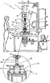
- Number 1 in the accompanying drawing indicates as a whole a machine tool for assembling known reducers 2.
- some reducers 2 comprise a cylindrical tubular input shaft 3, and machine 1 preferably, but not necessarily, provides for fitting a pinion 4 onto input shaft 3 of reducer 2 to form an interference fit between pinion 4 and an end portion 3a of shaft 3.
- Input shaft 3 normally forms part of an input portion 2a of reducer 2, which may be of various types depending on the type of reducer 2.
- input portion 2a of reducer 2 is defined by a known electric motor, and input shaft 3 by the output shaft of the electric motor.
- pinion 4 comprises a cylindrical end portion 4a having a diameter approximately equal to but no less than the inside diameter of input shaft 3 of reducer 2
- Machine 1 comprises a main supporting frame 5; a horizontal worktable 6 supported by frame 5; a fitting assembly 7 located over worktable 6 at an assembly station 8; and a supporting device 9 located on worktable 6 at station 8.
- Fitting assembly 7 comprises a known hydraulic actuator 10 located over station 8 and coaxial with a vertical reference axis 11 intersecting worktable 6 at station 8; and a pressurized-fluid supply unit 12 for selectively supplying pressurized fluid to hydraulic actuator 10, so that the rod 13 of hydraulic actuator 10 is extended towards worktable 6 and maintained coaxial with axis 11.
- Fitting assembly 7 also comprises a spindle 14 fitted to a free end 13a of rod 13, and which selectively retains and maintains pinion 4 coaxial with axis 11, with end portion 4a facing worktable 6.
- Fitting assembly 7 also comprises two sensors 15 and 16, the first of which for determining the travel of rod 13, and the second of which for determining the compression exerted by rod 13.
- sensor 16 is defined by a known load cell (e.g. an AEP load cell, model TC4-127-TN/10T) interposed between spindle 14 and the free end 13a of rod 13; and sensor 15 is defined by a known optical rule (e.g. an ELAP optical rule, model PD360) having two portions movable with respect to each other, a first of which is integral with rod 13 of hydraulic actuator 10, and a second of which is integral with the cylinder of hydraulic actuator 10 and provides for determining, via the first portion, the displacement of rod 13 of hydraulic actuator 10.
- a known load cell e.g. an AEP load cell, model TC4-127-TN/10T
- sensor 15 is defined by a known optical rule (e.g. an ELAP optical rule, model PD360) having two portions movable with respect to each other, a first of which is integral with rod 13 of hydraulic actuator 10, and a second of which is integral with the cylinder of hydraulic actuator 10 and provides for determining, via the first portion, the displacement of rod 13
- Supporting device 9 comprises a supporting frame 17 for supporting input portion 2a of reducer 2 at assembly station 8 with input shaft 3 of input portion 2a coaxial with axis 11; and a stop member 18 against which the end of shaft 3 facing worktable 6 rests when input portion 2a is positioned at assembly station 8. Stop member 18 provides for counteracting the compression exerted by rod 13 on shaft 3 to prevent damaging the rolling bearings on which shaft 3 rotates.
- stop member 18 is defined by a known hydraulic actuator 19 located coaxially with axis 11 on worktable 6, and the rod 20 of which is movable axially to and from a work position in which the free end of rod 20 contacts the end of shaft 3 facing worktable 6, when said pressurized fluid is supplied by unit 12.
- Supporting device 9 also comprises a hydraulic gripping assembly 21 in turn comprising a pair of jaws located on opposite sides of input portion 2a of reducer 2 at station 8.
- the jaws, indicated 21a and 21b, are movable to and from a gripping position to grip input portion 2a to frame 17 and keep shaft 3 coaxial with axis 11 when assembling pinion 4.
- Machine 1 also comprises a control unit 22 for controlling pressurized fluid supply to hydraulic actuator 10, gripping assembly 21 and hydraulic actuator 19 by means of a number of solenoid valves 23 along the conduits connected to pressurized-fluid supply unit 12.
- control unit 22 controls pressurized fluid supply to hydraulic actuator 10 to control the downward movement of rod 13 towards reducer 2 at station 8 as a function of the signals received from sensors 15 and 16.
- Control unit 22 also analyzes the signals from sensors 15 and 16 to determine fitment of pinion 4 to shaft 3 according to predetermined assembly specifications.
- control unit 22 also controls displacement of stop member 18 to and from said work position.
- gripping assembly 21 is movable with respect to worktable 6 to move input portions 2a of reducers 2 successively to and from assembly station 8, while at the same time gripping them to frame 17 when assembling pinion 4.
- the operator positions input portion 2a of reducer 2 on frame 17, so that input shaft 3 is coaxial with axis 11, with end portion 3a facing spindle 14, and fits pinion 4 inside spindle 14 so that pinion 4 is coaxial with axis 11, with end portion 4a facing end portion 3a of shaft 3.
- the operator operates gripping assembly 21 to grip input portion 2a to frame 17, and selects, on a control panel of control unit 22, the assembly specifications of the interference fit to be made by machine 1. If necessary, the assembly specifications may be memorized on control unit 22.
- control unit 22 controls pressurized fluid supply to hydraulic actuator 19 to move rod 20 into the work position.
- control unit 22 determines the position of shaft 3 along axis 11 to determine a "reference travel”, i.e. the travel required of rod 13 to position pinion 4 against shaft 3 without damaging the shaft. To determine the "reference travel”, control unit 22 controls pressurized fluid supply to hydraulic actuator 10 to extend rod 13 and position pinion 4 against shaft 3 without exerting any compression, and then determines the distance traveled by rod 13 by means of sensor 15.
- control unit 22 determines, as a function of the "reference travel” and the size of end portion 4a of pinion 4, an "assembly travel", i.e. the travel required of rod 13 to drive end portion 4a of pinion 4 inside end portion 3a of shaft 3 without damaging the shaft.
- control unit 22 controls pressurized fluid supply to hydraulic actuator 10 to perform the "assembly travel" of rod 13 and drive pinion 4 inside shaft 3, and, by means of sensors 15 and 16, monitors the compression exerted by hydraulic actuator 10 as a function of the distance traveled by rod 13 to ensure fitment according to assembly specifications.
- control unit 22 determines in real time the compression exerted by hydraulic actuator 10 in the portion of travel between the "reference travel” and "assembly travel", and indicates correct fitment of pinion 4 to shaft 3 when the compression value at the various points is maintained above a corresponding reference value contained in the assembly specifications.
- control unit 22 informs the operator that the shaft 3-pinion 4 assembly is defective and must be rejected.
- Machine 1 as described above may also be used for assembling pulleys, gears or similar to the input shaft of reducer 2.
- the gear may have a central through hole, and the input shaft therefore comprises a projecting end portion to which the gear is fitted.
- Pinion 4 may of course be assembled to input shaft 3 by inverting the positions of pinion 4 and input portion 2a of reducer 2 on machine 1, so that input portion 2a is fed towards pinion 4.
- the main advantage of machine 1 as described above is that of enabling gears to be assembled quickly and cheaply to reducers 2, so that the final stages in the assembly of reducer 2 may be transferred, with considerable economic advantages, to the place at which reducer 2 is actually marketed. That is, as production of reducers 2 need no longer be restricted to high-cost automated plants, certain components may be produced in the marketing area to reduce transport expenses.
- a further advantage of machine 1 as described above is that of enabling small-scale production of reducers with particular mechanical connections, and which would be extremely expensive if produced on large automated systems.
Landscapes
- Engineering & Computer Science (AREA)
- Mechanical Engineering (AREA)
- General Details Of Gearings (AREA)
- Automobile Manufacture Line, Endless Track Vehicle, Trailer (AREA)
- Automatic Assembly (AREA)
Applications Claiming Priority (2)
| Application Number | Priority Date | Filing Date | Title |
|---|---|---|---|
| ITBO970316 | 1997-05-26 | ||
| IT97BO000316A IT1292582B1 (it) | 1997-05-26 | 1997-05-26 | Metodo e macchina per l'assemblaggio di riduttori. |
Publications (1)
| Publication Number | Publication Date |
|---|---|
| EP0881027A1 true EP0881027A1 (de) | 1998-12-02 |
Family
ID=11342292
Family Applications (1)
| Application Number | Title | Priority Date | Filing Date |
|---|---|---|---|
| EP98109475A Withdrawn EP0881027A1 (de) | 1997-05-26 | 1998-05-25 | Verfahren und Vorrichtung zum Assemblieren von Untersetzungsgetrieben |
Country Status (2)
| Country | Link |
|---|---|
| EP (1) | EP0881027A1 (de) |
| IT (1) | IT1292582B1 (de) |
Cited By (4)
| Publication number | Priority date | Publication date | Assignee | Title |
|---|---|---|---|---|
| WO2000064627A1 (en) * | 1999-04-23 | 2000-11-02 | Veri-Tek, Inc. | Press operation verification system |
| CN106584348A (zh) * | 2016-11-30 | 2017-04-26 | 重庆速腾机械制造有限公司 | 用于离合器总泵活塞皮碗的安装装置 |
| CN109494943A (zh) * | 2019-01-07 | 2019-03-19 | 上海锡明光电科技有限公司 | 电动机转子组装定位系统、方法、装置、设备及介质 |
| CN115255918A (zh) * | 2022-07-29 | 2022-11-01 | 中国第一汽车股份有限公司 | 一种断开式驱动桥主减速器总成装配装置以及方法 |
Families Citing this family (1)
| Publication number | Priority date | Publication date | Assignee | Title |
|---|---|---|---|---|
| CN116728345B (zh) * | 2023-07-27 | 2025-10-31 | 共享装备股份有限公司 | 一种外壳拆解装置 |
Citations (7)
| Publication number | Priority date | Publication date | Assignee | Title |
|---|---|---|---|---|
| JPS5937862A (ja) * | 1982-08-27 | 1984-03-01 | Alps Electric Co Ltd | 小型モ−タ−のプ−リ−取付方法 |
| JPS59107833A (ja) * | 1982-12-10 | 1984-06-22 | Hakko Denki Seisakusho:Kk | 圧入監視装置 |
| US4524503A (en) * | 1982-01-20 | 1985-06-25 | Toyota Jidosha Kabushiki Kaisha | Method and apparatus for hydraulically assembling a driven shaft and a drive member |
| JPS60161040A (ja) * | 1984-01-27 | 1985-08-22 | Sharp Corp | 軸類の圧入装置 |
| JPS61203237A (ja) * | 1985-03-04 | 1986-09-09 | Caterpillar Mitsubishi Ltd | 圧入部品の良否判別方法 |
| DE3911033A1 (de) * | 1989-04-05 | 1990-10-11 | Oesterr Forsch Seibersdorf | Press- bzw. pruefzelle |
| US5159754A (en) * | 1991-03-20 | 1992-11-03 | The Budd Company | Process for press fitting a vehicle wheel hub into an integral bearing |
-
1997
- 1997-05-26 IT IT97BO000316A patent/IT1292582B1/it active IP Right Grant
-
1998
- 1998-05-25 EP EP98109475A patent/EP0881027A1/de not_active Withdrawn
Patent Citations (7)
| Publication number | Priority date | Publication date | Assignee | Title |
|---|---|---|---|---|
| US4524503A (en) * | 1982-01-20 | 1985-06-25 | Toyota Jidosha Kabushiki Kaisha | Method and apparatus for hydraulically assembling a driven shaft and a drive member |
| JPS5937862A (ja) * | 1982-08-27 | 1984-03-01 | Alps Electric Co Ltd | 小型モ−タ−のプ−リ−取付方法 |
| JPS59107833A (ja) * | 1982-12-10 | 1984-06-22 | Hakko Denki Seisakusho:Kk | 圧入監視装置 |
| JPS60161040A (ja) * | 1984-01-27 | 1985-08-22 | Sharp Corp | 軸類の圧入装置 |
| JPS61203237A (ja) * | 1985-03-04 | 1986-09-09 | Caterpillar Mitsubishi Ltd | 圧入部品の良否判別方法 |
| DE3911033A1 (de) * | 1989-04-05 | 1990-10-11 | Oesterr Forsch Seibersdorf | Press- bzw. pruefzelle |
| US5159754A (en) * | 1991-03-20 | 1992-11-03 | The Budd Company | Process for press fitting a vehicle wheel hub into an integral bearing |
Non-Patent Citations (4)
| Title |
|---|
| PATENT ABSTRACTS OF JAPAN vol. 008, no. 127 (E - 250) 14 June 1984 (1984-06-14) * |
| PATENT ABSTRACTS OF JAPAN vol. 008, no. 227 (M - 332) 18 October 1984 (1984-10-18) * |
| PATENT ABSTRACTS OF JAPAN vol. 009, no. 326 (M - 441) 21 December 1985 (1985-12-21) * |
| PATENT ABSTRACTS OF JAPAN vol. 011, no. 034 (M - 558) 31 January 1987 (1987-01-31) * |
Cited By (7)
| Publication number | Priority date | Publication date | Assignee | Title |
|---|---|---|---|---|
| WO2000064627A1 (en) * | 1999-04-23 | 2000-11-02 | Veri-Tek, Inc. | Press operation verification system |
| US6490775B1 (en) | 1999-04-23 | 2002-12-10 | Veri-Tek Inc. | Press operation verification system |
| CN106584348A (zh) * | 2016-11-30 | 2017-04-26 | 重庆速腾机械制造有限公司 | 用于离合器总泵活塞皮碗的安装装置 |
| CN106584348B (zh) * | 2016-11-30 | 2020-06-02 | 重庆速腾机械制造有限公司 | 用于离合器总泵活塞皮碗的安装装置 |
| CN109494943A (zh) * | 2019-01-07 | 2019-03-19 | 上海锡明光电科技有限公司 | 电动机转子组装定位系统、方法、装置、设备及介质 |
| CN115255918A (zh) * | 2022-07-29 | 2022-11-01 | 中国第一汽车股份有限公司 | 一种断开式驱动桥主减速器总成装配装置以及方法 |
| CN115255918B (zh) * | 2022-07-29 | 2024-01-30 | 中国第一汽车股份有限公司 | 一种断开式驱动桥主减速器总成装配装置以及方法 |
Also Published As
| Publication number | Publication date |
|---|---|
| IT1292582B1 (it) | 1999-02-08 |
| ITBO970316A0 (it) | 1997-05-26 |
| ITBO970316A1 (it) | 1998-11-26 |
Similar Documents
| Publication | Publication Date | Title |
|---|---|---|
| CN108714500B (zh) | 一种车轮螺栓孔防护堵放置装置 | |
| US10259278B2 (en) | Online inflating valve insertion device | |
| US3830382A (en) | Article handling apparatus with spring-assisted pantagraph raising mechanism | |
| US20070271982A1 (en) | Metal spinning machine | |
| CN104669013B (zh) | 物体固定装置、机床、机器人以及物体固定方法 | |
| EP0881028B1 (de) | Werkzeug für Maschinen zur Montage von Motor-Untersetzungsgetrieben | |
| EP0881027A1 (de) | Verfahren und Vorrichtung zum Assemblieren von Untersetzungsgetrieben | |
| CN109434453A (zh) | 一种汽车轮毂转向节自动装配机及装配方法 | |
| JP4421530B2 (ja) | バルブガイドおよびバルブシートの圧入装置 | |
| CN108058025A (zh) | 一种组合机床多工位加工结构 | |
| CN211361519U (zh) | 凸轮式自动旋转升降换刀机构 | |
| JP2008036716A (ja) | ワーク把持装置 | |
| EP1346792A1 (de) | Schweiss- bzw. Fügeeinheit | |
| CN108622231A (zh) | 车辆部件安装系统及其控制方法 | |
| US4805299A (en) | Working apparatus for use in an assembling/processing line | |
| KR100667380B1 (ko) | 엔진의 유동통로 마감 장치 | |
| CN204913079U (zh) | 一种筒体加强圈组焊工作站 | |
| US4388576A (en) | Electric servo drive air cylinder | |
| JPS61249231A (ja) | 圧入、締付け複合装置 | |
| US4047413A (en) | Automatic metal-spinning method | |
| JP3279329B2 (ja) | カムシャフトの製造装置 | |
| CN111038962B (zh) | 一种用于动车零部件加工的流水线机器人 | |
| EP1743735B1 (de) | Werkstücksgreifvorrichtung für ein Werkzeughalter-System von einer Werkzeugmaschine | |
| CN110900181B (zh) | 一种球形桥梁支座上下板自动化生产线 | |
| RU1776528C (ru) | Установка дл аргонодуговой сварки поворотных стыков труб неплав щимс электродом с подачей присадочной проволоки |
Legal Events
| Date | Code | Title | Description |
|---|---|---|---|
| PUAI | Public reference made under article 153(3) epc to a published international application that has entered the european phase |
Free format text: ORIGINAL CODE: 0009012 |
|
| AK | Designated contracting states |
Kind code of ref document: A1 Designated state(s): BE DE ES FR GB IT SE |
|
| AX | Request for extension of the european patent |
Free format text: AL;LT;LV;MK;RO;SI |
|
| AKX | Designation fees paid |
Free format text: BE DE ES FR GB IT SE |
|
| STAA | Information on the status of an ep patent application or granted ep patent |
Free format text: STATUS: THE APPLICATION IS DEEMED TO BE WITHDRAWN |
|
| 18D | Application deemed to be withdrawn |
Effective date: 19990603 |