EP0881104A1 - Reifen mit zwei Wulstkernen per Wulst - Google Patents
Reifen mit zwei Wulstkernen per Wulst Download PDFInfo
- Publication number
- EP0881104A1 EP0881104A1 EP98109265A EP98109265A EP0881104A1 EP 0881104 A1 EP0881104 A1 EP 0881104A1 EP 98109265 A EP98109265 A EP 98109265A EP 98109265 A EP98109265 A EP 98109265A EP 0881104 A1 EP0881104 A1 EP 0881104A1
- Authority
- EP
- European Patent Office
- Prior art keywords
- rim
- rod
- diameter
- mounting
- bead
- Prior art date
- Legal status (The legal status is an assumption and is not a legal conclusion. Google has not performed a legal analysis and makes no representation as to the accuracy of the status listed.)
- Granted
Links
- 239000011324 bead Substances 0.000 title claims abstract description 46
- 230000002787 reinforcement Effects 0.000 claims description 6
- 238000004804 winding Methods 0.000 claims description 3
- 230000014759 maintenance of location Effects 0.000 abstract 1
- 241000531908 Aramides Species 0.000 description 3
- 229920003235 aromatic polyamide Polymers 0.000 description 3
- 239000004760 aramid Substances 0.000 description 2
- 230000003416 augmentation Effects 0.000 description 2
- 230000006835 compression Effects 0.000 description 2
- 238000007906 compression Methods 0.000 description 2
- 230000008520 organization Effects 0.000 description 2
- OKTJSMMVPCPJKN-UHFFFAOYSA-N Carbon Chemical compound [C] OKTJSMMVPCPJKN-UHFFFAOYSA-N 0.000 description 1
- 241000287107 Passer Species 0.000 description 1
- 229910000831 Steel Inorganic materials 0.000 description 1
- 229910052799 carbon Inorganic materials 0.000 description 1
- 230000007547 defect Effects 0.000 description 1
- 239000002184 metal Substances 0.000 description 1
- 229920000642 polymer Polymers 0.000 description 1
- 230000001681 protective effect Effects 0.000 description 1
- 238000007789 sealing Methods 0.000 description 1
- 239000010959 steel Substances 0.000 description 1
- 239000004753 textile Substances 0.000 description 1
Images
Classifications
-
- B—PERFORMING OPERATIONS; TRANSPORTING
- B60—VEHICLES IN GENERAL
- B60C—VEHICLE TYRES; TYRE INFLATION; TYRE CHANGING; CONNECTING VALVES TO INFLATABLE ELASTIC BODIES IN GENERAL; DEVICES OR ARRANGEMENTS RELATED TO TYRES
- B60C15/00—Tyre beads, e.g. ply turn-up or overlap
- B60C15/02—Seating or securing beads on rims
- B60C15/024—Bead contour, e.g. lips, grooves, or ribs
-
- B—PERFORMING OPERATIONS; TRANSPORTING
- B60—VEHICLES IN GENERAL
- B60C—VEHICLE TYRES; TYRE INFLATION; TYRE CHANGING; CONNECTING VALVES TO INFLATABLE ELASTIC BODIES IN GENERAL; DEVICES OR ARRANGEMENTS RELATED TO TYRES
- B60C15/00—Tyre beads, e.g. ply turn-up or overlap
- B60C15/04—Bead cores
- B60C15/05—Bead cores multiple, i.e. with two or more cores in each bead
Definitions
- the present invention relates to tire casings.
- the invention relates in particular to tire casings, each bead of which has two rods.
- the envelope in accordance with EP-A-168754 is intended to be mounted on a rim of which at least one bead seat extends axially inwards by a projection axial retainer (called hump).
- the bead of this envelope has two rods, one of which is close to the point of the bead, towards the inside of the envelope, and the other ensures a blockage of the first in the event of heavy loads axial.
- the two rods are joined by a carcass ply to improve this collaboration.
- the resistance to loosening is therefore due basically the action of the second rod on the first and the action anti-loosening is not always sufficient.
- JP-A-5 178 033 describes a secondary rod applied against the rim, under a main rod or next to this main rod, to improve uniformity radial avoiding eccentricity defects. This request is not affected by loosening problems.
- the object of the invention is to propose a tire covering which can be used on a rim with hump, this envelope allowing the bead to be held in place on the rim seat in extreme driving conditions at low pressure or at zero pressure, in a straight line or in strong drift, this envelope allowing also avoid or greatly reduce the rotation of the bead on the rim in the case of passage of high power torque.
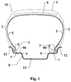
- FIG. 1 shows a tire casing 10 according to the invention.
- This envelope 10 has a top 1, two sides 2, and two beads 3.
- the vertex 1 is reinforced by a known vertex reinforcement 4, constituted by example of two crossed tablecloths not shown in the drawing for the purpose of simplification.
- a carcass ply 5 passes from a bead 3 to the other by winding, in each bead, around a main rod 6.
- Each bead 3 further comprises a secondary rod 7 arranged in the lower part of this bead.
- the casing is shown arranged on a rim 8 comprising two humps 9, each bead 3 being in contact with or near a hump 9.
- the rim 8 furthermore comprises a groove 11 and two rim hooks 12.
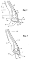
- FIG. 2 shows in more detail a bead 3 of the casing 10. This bead is assumed to be mounted on the rim 8 which is not shown in the drawing for the purpose of simplification.
- D 9 represents the diameter of the apex 90 of the hump 9 in contact with or near the bead 3
- D e6 represents the outside diameter of the main rod 6.
- D i6 represents the internal diameter of this rod 6
- D e7 represents the outside diameter of the secondary rod 7
- D i7 represents the internal diameter of this rod 7.
- Each of these diameters is the diameter of a circle whose axis is the axis of revolution of the casing 10, and therefore of the rim 8, this axis, not shown on the drawing for the purpose of simplification, being parallel to the straight line D in FIG. 2.
- D i6 and therefore D e6 , after mounting on the rim 8, are practically identical to the corresponding diameters of the main rod 6 before its mounting on the rim 8, that is to say that this rod does not undergo practically no elongation during assembly of the casing 10 on the rim 8.
- the diameter D i7 of the secondary rod 7 mounted on the rim 8 is 1.5 to 3% greater than this diameter before the assembly of the casing 10 on the rim 8, that is to say that the bead wire 7 is subjected to a tensile stress after this mounting.
- the diameter D i3 measured along the axis of rotation of the envelope, in the plane perpendicular to this axis and containing l the axis of the rod 7 is 1.5 to 3% greater than this diameter before mounting on the rim 8.
- the values of D i7 and D i3 after mounting on the rim 8 are equal to 1.015- 1.030 times the respective values of these diameters before mounting.
- the maximum elastic elongation of the main rod 6 is at most equal to 1.5%, that is to say that this rod is very rigid.
- the secondary bead wire 7 has a maximum elastic elongation at least equal to 3%, that is to say that it is relatively flexible and that it can still lengthen after mounting on the rim 8.
- the relative flexibility of the secondary rod 7 makes it possible to increase its internal diameter D i7 with a disassembly tool to mount the casing 10 on the rim 8, or to remove it from this rim during disassembly. It may be appropriate for this purpose to provide a protective tongue 14 between the secondary rod 7 and the underside 15 of the bead 3, to prevent the disassembly tool from damaging the bead 3.
- This tongue is for example made of 'a sheet reinforced with metallic or textile threads and it can possibly extend upwards on the inside of the bead to increase the protection, as shown in Figure 2.
- the tongue 14 is not shown in Figure 1 in a aim of simplification.
- the main rod 6 is for example made up of metal reinforcements, in particular wires or profiles, this rod can for example be a classic rod of the "braided rod” type or of the "bundle rod” type. We can however, also use high tenacity non-metallic reinforcements.
- the relatively flexible secondary rod 7 is preferably made with non-metallic reinforcements, for example carbon or polymer wires organic with great tenacity, especially aramid.
- the module in traction of the secondary rod 7 is at least equal to 10 000 MPa (megapascals) to guarantee good resistance to loosening.
- the maximum elastic elongation of the secondary rod 7 is at less than 4%.
- wire should be taken in a very general sense, a wire can be made by a single monofilament or multifilament yarn or by a set of such yarns twisted together, in particular forming cables or plies.
- a radial envelope in accordance with the invention of dimension 175-70R13 is produced.
- a control envelope is produced which is not in accordance with the invention.
- This envelope is identical to the envelope according to the invention, with the difference that it does not have a secondary rod 7.
- These two envelopes have the same external geometry, and therefore the value of the diameter D i3 is the same for the two envelopes, the diameter D i3 of the control envelope being measured at the same location of the envelope as for the envelope according to the invention.
- This diameter D i3 before mounting on the rim 8, is equal to 321 mm and it is less than the diameter D i3 of a conventional envelope of the same dimension (325.3 mm), which makes it possible to compare envelopes of identical dimensions these two envelopes therefore undergoing a more pronounced tightening on the rim than a conventional envelope of this dimension.
- rims are mounted on a vehicle and they are driven at 50 km / h on a radius of 20 m by reducing the pressure until the appearance of a loosening.
- the release pressure is 0 bar for the envelope conforming to the invention, whereas it is 1 bar for the control envelope.
- the envelope according to the invention therefore undergoes a loosening only in an extreme case of deflation when there is no more pressure in the envelope, while the envelope not in accordance with the invention undergoes a loosening well before, while it remains a significant pressure in the envelope and this despite a greater tightening than in a classic envelope, as noted above.
- the invention therefore makes it possible to very significantly delay the onset of loosening and therefore delay very notably the phenomenon of backlash, which considerably improves the security of this envelope, at the cost of a slight disadvantage which is the pressure more high for mounting the envelope according to the invention.
- Figure 3 shows another embodiment of the invention.
- the bead 3 'of this envelope 10' is identical to the bead 3 of the envelope 10 with the difference that the bead 3 'has an area 60, under the main rod 6, whose average diameter D 60 before mounting on the rim 8 is greater than the diameter D i3 before mounting and corresponds practically to the diameter of a conventional envelope measured at the same location on the envelope.
- This embodiment has the advantage of having an inflation pressure for the passage of the hump which is close to this pressure for a conventional envelope, while however being superior thereto, which can facilitate assembly with respect to the envelope 8 which does not does not have this area 60.
Landscapes
- Engineering & Computer Science (AREA)
- Mechanical Engineering (AREA)
- Tires In General (AREA)
Applications Claiming Priority (2)
| Application Number | Priority Date | Filing Date | Title |
|---|---|---|---|
| FR9706763 | 1997-05-30 | ||
| FR9706763A FR2763894A1 (fr) | 1997-05-30 | 1997-05-30 | Enveloppe de pneumatiques dont chaque bourrelet comporte deux tringles |
Publications (2)
| Publication Number | Publication Date |
|---|---|
| EP0881104A1 true EP0881104A1 (de) | 1998-12-02 |
| EP0881104B1 EP0881104B1 (de) | 2002-01-30 |
Family
ID=9507498
Family Applications (1)
| Application Number | Title | Priority Date | Filing Date |
|---|---|---|---|
| EP98109265A Expired - Lifetime EP0881104B1 (de) | 1997-05-30 | 1998-05-22 | Reifen mit zwei Wulstkernen per Wulst |
Country Status (10)
| Country | Link |
|---|---|
| US (1) | US5968296A (de) |
| EP (1) | EP0881104B1 (de) |
| JP (1) | JP4275215B2 (de) |
| CN (1) | CN1094842C (de) |
| BR (1) | BR9801698A (de) |
| CA (1) | CA2238909A1 (de) |
| DE (1) | DE69803622T2 (de) |
| ES (1) | ES2170979T3 (de) |
| FR (1) | FR2763894A1 (de) |
| RU (1) | RU2196687C2 (de) |
Cited By (2)
| Publication number | Priority date | Publication date | Assignee | Title |
|---|---|---|---|---|
| EP1666278A4 (de) * | 2003-09-12 | 2008-03-26 | Bridgestone Corp | Luftreifen |
| FR2998513A1 (fr) * | 2012-11-29 | 2014-05-30 | Michelin & Cie | Bourrelet de pneumatique pour avion |
Families Citing this family (8)
| Publication number | Priority date | Publication date | Assignee | Title |
|---|---|---|---|---|
| US6494242B2 (en) * | 1999-05-27 | 2002-12-17 | Michelin Recherche Et Technique | Runflat tire having optimized carcass path |
| BR0101507A (pt) * | 2000-04-28 | 2001-11-27 | Goodyear Tire & Rubber | Perfil de talão para pneumáticos |
| DE10327678A1 (de) * | 2003-06-20 | 2005-01-05 | Continental Aktiengesellschaft | Fahrzeugluftreifen |
| JP2005193758A (ja) * | 2004-01-06 | 2005-07-21 | Yokohama Rubber Co Ltd:The | 空気入りタイヤ |
| JP4464700B2 (ja) * | 2004-01-28 | 2010-05-19 | 住友ゴム工業株式会社 | 空気入りタイヤ及びその製造方法 |
| FR2977828B1 (fr) * | 2011-07-13 | 2013-08-16 | Michelin Soc Tech | Pneumatique pliable, procede de pliage et utilisation |
| JP6988415B2 (ja) * | 2017-12-04 | 2022-01-05 | 横浜ゴム株式会社 | 空気入りタイヤ |
| DE102019216915A1 (de) * | 2019-11-04 | 2021-05-06 | Continental Reifen Deutschland Gmbh | Fahrzeugluftreifen mit Felgenschutzrippe |
Citations (6)
| Publication number | Priority date | Publication date | Assignee | Title |
|---|---|---|---|---|
| EP0167283A2 (de) * | 1984-06-28 | 1986-01-08 | Dunlop Limited | Luftreifen |
| EP0168754A1 (de) * | 1984-07-19 | 1986-01-22 | MICHELIN & CIE (Compagnie Générale des Etablissements Michelin) Société dite: | Gürtelreifen mit zwei Wulstkernen per Wulst |
| JPH03243404A (ja) * | 1990-02-21 | 1991-10-30 | Yokohama Rubber Co Ltd:The | 重荷重用空気入りラジアルタイヤ |
| FR2678544A1 (fr) * | 1991-07-03 | 1993-01-08 | Michelin & Cie | Procede de fabrication d'un pneumatique a armature de carcasse radiale, et pneumatique obtenu. |
| EP0634297A1 (de) * | 1993-07-12 | 1995-01-18 | Compagnie Generale Des Etablissements Michelin-Michelin & Cie | Reifen für LKW |
| EP0770504A1 (de) * | 1995-10-23 | 1997-05-02 | Sumitomo Rubber Industries Limited | Luftreifen |
Family Cites Families (2)
| Publication number | Priority date | Publication date | Assignee | Title |
|---|---|---|---|---|
| US779730A (en) * | 1904-05-28 | 1905-01-10 | Kokomo Rubber Company | Vehicle-tire. |
| JPH06191242A (ja) * | 1992-12-24 | 1994-07-12 | Yokohama Rubber Co Ltd:The | 空気入りタイヤ |
-
1997
- 1997-05-30 FR FR9706763A patent/FR2763894A1/fr active Pending
-
1998
- 1998-05-22 DE DE69803622T patent/DE69803622T2/de not_active Expired - Lifetime
- 1998-05-22 ES ES98109265T patent/ES2170979T3/es not_active Expired - Lifetime
- 1998-05-22 EP EP98109265A patent/EP0881104B1/de not_active Expired - Lifetime
- 1998-05-26 BR BR9801698-9A patent/BR9801698A/pt not_active IP Right Cessation
- 1998-05-28 US US09/086,163 patent/US5968296A/en not_active Expired - Lifetime
- 1998-05-29 RU RU98110365/28A patent/RU2196687C2/ru not_active IP Right Cessation
- 1998-05-29 CA CA002238909A patent/CA2238909A1/fr not_active Abandoned
- 1998-05-29 CN CN98102301A patent/CN1094842C/zh not_active Expired - Fee Related
- 1998-06-01 JP JP15089398A patent/JP4275215B2/ja not_active Expired - Lifetime
Patent Citations (6)
| Publication number | Priority date | Publication date | Assignee | Title |
|---|---|---|---|---|
| EP0167283A2 (de) * | 1984-06-28 | 1986-01-08 | Dunlop Limited | Luftreifen |
| EP0168754A1 (de) * | 1984-07-19 | 1986-01-22 | MICHELIN & CIE (Compagnie Générale des Etablissements Michelin) Société dite: | Gürtelreifen mit zwei Wulstkernen per Wulst |
| JPH03243404A (ja) * | 1990-02-21 | 1991-10-30 | Yokohama Rubber Co Ltd:The | 重荷重用空気入りラジアルタイヤ |
| FR2678544A1 (fr) * | 1991-07-03 | 1993-01-08 | Michelin & Cie | Procede de fabrication d'un pneumatique a armature de carcasse radiale, et pneumatique obtenu. |
| EP0634297A1 (de) * | 1993-07-12 | 1995-01-18 | Compagnie Generale Des Etablissements Michelin-Michelin & Cie | Reifen für LKW |
| EP0770504A1 (de) * | 1995-10-23 | 1997-05-02 | Sumitomo Rubber Industries Limited | Luftreifen |
Non-Patent Citations (1)
| Title |
|---|
| PATENT ABSTRACTS OF JAPAN vol. 016, no. 034 (M - 1204) 28 January 1992 (1992-01-28) * |
Cited By (7)
| Publication number | Priority date | Publication date | Assignee | Title |
|---|---|---|---|---|
| EP1666278A4 (de) * | 2003-09-12 | 2008-03-26 | Bridgestone Corp | Luftreifen |
| US7575032B2 (en) | 2003-09-12 | 2009-08-18 | Bridgestone Corporation | Pneumatic tire |
| FR2998513A1 (fr) * | 2012-11-29 | 2014-05-30 | Michelin & Cie | Bourrelet de pneumatique pour avion |
| WO2014083090A1 (fr) * | 2012-11-29 | 2014-06-05 | Compagnie Generale Des Etablissements Michelin | Bourrelet de pneumatique pour avion |
| CN104822546A (zh) * | 2012-11-29 | 2015-08-05 | 米其林集团总公司 | 用于航空器的轮胎胎圈 |
| CN104822546B (zh) * | 2012-11-29 | 2017-06-30 | 米其林集团总公司 | 用于航空器的轮胎胎圈 |
| US9895938B2 (en) | 2012-11-29 | 2018-02-20 | Compagnie Generale Des Etablissments Michelin | Tire bead for aircraft |
Also Published As
| Publication number | Publication date |
|---|---|
| ES2170979T3 (es) | 2002-08-16 |
| RU2196687C2 (ru) | 2003-01-20 |
| BR9801698A (pt) | 1999-09-28 |
| FR2763894A1 (fr) | 1998-12-04 |
| EP0881104B1 (de) | 2002-01-30 |
| JPH1111116A (ja) | 1999-01-19 |
| DE69803622D1 (de) | 2002-03-14 |
| US5968296A (en) | 1999-10-19 |
| DE69803622T2 (de) | 2002-09-12 |
| CN1094842C (zh) | 2002-11-27 |
| CN1200994A (zh) | 1998-12-09 |
| CA2238909A1 (fr) | 1998-11-30 |
| JP4275215B2 (ja) | 2009-06-10 |
Similar Documents
| Publication | Publication Date | Title |
|---|---|---|
| EP0773115B1 (de) | Radialer LKW-Reifen mit einer mehrteiligen Gürtelschicht | |
| CA2281622C (fr) | Pneumatique de rapport de forme h/s < 0,6 | |
| EP1084047B1 (de) | Verstärkter radialreifenwulst | |
| EP0634297B1 (de) | Reifen für LKW | |
| EP0881104B1 (de) | Reifen mit zwei Wulstkernen per Wulst | |
| CA2081118C (fr) | Pneumatique dont les bourrelets a sieges tronconiques sont munis d'au moins une tringle principale et d'une tringle auxiliaire | |
| WO2005072992A1 (fr) | Pneumatique a flancs autoporteurs asymetriques | |
| EP3484726A1 (de) | Reifen mit wulstbereich mit reduziertem gewicht | |
| FR3050962A1 (fr) | Pneumatique dont la zone du bourrelet est allegee | |
| EP1395448B1 (de) | Luftreifen mit einer karkasse, die zweiverankerung enthält | |
| EP1565328B1 (de) | Gewellte seitenwände aufweisender reifen mit grösserer mobilität | |
| EP2121353B1 (de) | Zusätzliche seitenwandverstärkung für einen reifen für ein schwer-nutzfahrzeug | |
| EP2285594B1 (de) | Verstärkter reifen für lastkraftwagen | |
| EP1776248B1 (de) | Reifenwulst | |
| EP2931537B1 (de) | Wulst eines reifens für baumaschinen-schwerlastfahrzeuge | |
| EP1578620B1 (de) | Notlaufreifen mit seitenwänden mit unterschiedlicher steifigkeit | |
| WO2017191422A1 (fr) | Pneumatique dont la zone du bourrelet est allégée | |
| EP1648716B1 (de) | Luftreifen für schwerfahrzeuge | |
| EP2931538B1 (de) | Reifenwulst für schwerlastfahrzeug | |
| EP3484728A1 (de) | Reifen mit wulstbereich mit reduziertem gewicht | |
| EP2569172B1 (de) | Reifen mit verbessertem wulst | |
| EP1789266B1 (de) | Reifen mit erweiterter mobilität, der mehrere sehr niedrige ankerbereiche aufweist | |
| WO2000071366A1 (fr) | Bourrelet sans tringle pour pneumatique | |
| EP1101633B1 (de) | Lufftreifen mit entkoppelter niedriger Zone | |
| FR3068301A1 (fr) | Pneumatique dont la zone du bourrelet est allegee |
Legal Events
| Date | Code | Title | Description |
|---|---|---|---|
| PUAI | Public reference made under article 153(3) epc to a published international application that has entered the european phase |
Free format text: ORIGINAL CODE: 0009012 |
|
| AK | Designated contracting states |
Kind code of ref document: A1 Designated state(s): DE ES FR GB IT |
|
| AX | Request for extension of the european patent |
Free format text: AL;LT;LV;MK;RO;SI |
|
| 17P | Request for examination filed |
Effective date: 19990602 |
|
| AKX | Designation fees paid |
Free format text: DE ES FR GB IT |
|
| GRAG | Despatch of communication of intention to grant |
Free format text: ORIGINAL CODE: EPIDOS AGRA |
|
| 17Q | First examination report despatched |
Effective date: 20010402 |
|
| GRAG | Despatch of communication of intention to grant |
Free format text: ORIGINAL CODE: EPIDOS AGRA |
|
| GRAH | Despatch of communication of intention to grant a patent |
Free format text: ORIGINAL CODE: EPIDOS IGRA |
|
| GRAH | Despatch of communication of intention to grant a patent |
Free format text: ORIGINAL CODE: EPIDOS IGRA |
|
| GRAA | (expected) grant |
Free format text: ORIGINAL CODE: 0009210 |
|
| REG | Reference to a national code |
Ref country code: GB Ref legal event code: IF02 |
|
| AK | Designated contracting states |
Kind code of ref document: B1 Designated state(s): DE ES FR GB IT |
|
| GBT | Gb: translation of ep patent filed (gb section 77(6)(a)/1977) |
Effective date: 20020130 |
|
| REF | Corresponds to: |
Ref document number: 69803622 Country of ref document: DE Date of ref document: 20020314 |
|
| REG | Reference to a national code |
Ref country code: ES Ref legal event code: FG2A Ref document number: 2170979 Country of ref document: ES Kind code of ref document: T3 |
|
| PLBE | No opposition filed within time limit |
Free format text: ORIGINAL CODE: 0009261 |
|
| STAA | Information on the status of an ep patent application or granted ep patent |
Free format text: STATUS: NO OPPOSITION FILED WITHIN TIME LIMIT |
|
| 26N | No opposition filed | ||
| PGFP | Annual fee paid to national office [announced via postgrant information from national office to epo] |
Ref country code: ES Payment date: 20080529 Year of fee payment: 11 |
|
| PGFP | Annual fee paid to national office [announced via postgrant information from national office to epo] |
Ref country code: GB Payment date: 20080522 Year of fee payment: 11 |
|
| GBPC | Gb: european patent ceased through non-payment of renewal fee |
Effective date: 20090522 |
|
| PG25 | Lapsed in a contracting state [announced via postgrant information from national office to epo] |
Ref country code: GB Free format text: LAPSE BECAUSE OF NON-PAYMENT OF DUE FEES Effective date: 20090522 |
|
| REG | Reference to a national code |
Ref country code: ES Ref legal event code: FD2A Effective date: 20090523 |
|
| PG25 | Lapsed in a contracting state [announced via postgrant information from national office to epo] |
Ref country code: ES Free format text: LAPSE BECAUSE OF NON-PAYMENT OF DUE FEES Effective date: 20090523 |
|
| PGFP | Annual fee paid to national office [announced via postgrant information from national office to epo] |
Ref country code: DE Payment date: 20120523 Year of fee payment: 15 |
|
| PGFP | Annual fee paid to national office [announced via postgrant information from national office to epo] |
Ref country code: FR Payment date: 20120601 Year of fee payment: 15 |
|
| PGFP | Annual fee paid to national office [announced via postgrant information from national office to epo] |
Ref country code: IT Payment date: 20120531 Year of fee payment: 15 |
|
| PG25 | Lapsed in a contracting state [announced via postgrant information from national office to epo] |
Ref country code: DE Free format text: LAPSE BECAUSE OF NON-PAYMENT OF DUE FEES Effective date: 20131203 |
|
| REG | Reference to a national code |
Ref country code: DE Ref legal event code: R119 Ref document number: 69803622 Country of ref document: DE Effective date: 20131203 |
|
| PG25 | Lapsed in a contracting state [announced via postgrant information from national office to epo] |
Ref country code: IT Free format text: LAPSE BECAUSE OF NON-PAYMENT OF DUE FEES Effective date: 20130522 |
|
| REG | Reference to a national code |
Ref country code: FR Ref legal event code: ST Effective date: 20140131 |
|
| PG25 | Lapsed in a contracting state [announced via postgrant information from national office to epo] |
Ref country code: FR Free format text: LAPSE BECAUSE OF NON-PAYMENT OF DUE FEES Effective date: 20130531 |