EP0881176A1 - Vorrichtung zum Entfernen und Einfügen von flächigen Produkten in aufrechter Position - Google Patents
Vorrichtung zum Entfernen und Einfügen von flächigen Produkten in aufrechter Position Download PDFInfo
- Publication number
- EP0881176A1 EP0881176A1 EP98201481A EP98201481A EP0881176A1 EP 0881176 A1 EP0881176 A1 EP 0881176A1 EP 98201481 A EP98201481 A EP 98201481A EP 98201481 A EP98201481 A EP 98201481A EP 0881176 A1 EP0881176 A1 EP 0881176A1
- Authority
- EP
- European Patent Office
- Prior art keywords
- members
- removing members
- path
- products
- guides
- Prior art date
- Legal status (The legal status is an assumption and is not a legal conclusion. Google has not performed a legal analysis and makes no representation as to the accuracy of the status listed.)
- Withdrawn
Links
- 230000008878 coupling Effects 0.000 claims description 18
- 238000010168 coupling process Methods 0.000 claims description 18
- 238000005859 coupling reaction Methods 0.000 claims description 18
- 238000004806 packaging method and process Methods 0.000 description 2
- 230000005540 biological transmission Effects 0.000 description 1
- 235000015895 biscuits Nutrition 0.000 description 1
- 238000011179 visual inspection Methods 0.000 description 1
Images


Classifications
-
- B—PERFORMING OPERATIONS; TRANSPORTING
- B65—CONVEYING; PACKING; STORING; HANDLING THIN OR FILAMENTARY MATERIAL
- B65B—MACHINES, APPARATUS OR DEVICES FOR, OR METHODS OF, PACKAGING ARTICLES OR MATERIALS; UNPACKING
- B65B23/00—Packaging fragile or shock-sensitive articles other than bottles; Unpacking eggs
- B65B23/10—Packaging biscuits
- B65B23/12—Arranging, feeding or orientating the biscuits to be packaged
- B65B23/14—Forming groups of biscuits
-
- B—PERFORMING OPERATIONS; TRANSPORTING
- B65—CONVEYING; PACKING; STORING; HANDLING THIN OR FILAMENTARY MATERIAL
- B65G—TRANSPORT OR STORAGE DEVICES, e.g. CONVEYORS FOR LOADING OR TIPPING, SHOP CONVEYOR SYSTEMS OR PNEUMATIC TUBE CONVEYORS
- B65G57/00—Stacking of articles
- B65G57/32—Stacking of articles characterised by stacking during transit
Definitions
- the invention relates to a device for removing and inserting flat products positioned upright, which are fed in a number of channels and which are provided with feed stopping members and removing members.
- a device by which such products can be taken from a number of channels is known from e.g. EP-A-0 128 669.
- the fed products are stopped at the ends of the channels, until a removing member has been positioned in alignment with said channel.
- the stopping member is moved upwards, due to which the products can slide to the removing member.
- the stopping member is brought to a backward position in the row and is inserted between the products and is then returned to the end of the channel.
- a row of products of a predetermined length can be fed to the removing member and then to e.g. a packaging device with the help of the removing member.
- EP-A-0 164 305 discloses a device in which a row of products of a predetermined length is fed from a feed channel to a removing member. To that end, in addition to a stopping member, a separate member has been provided that can be inserted into the row of products at the desired distance. The distance has been made adjustable, in which a rather complex drive system has been provided for driving the various members.
- the object of the invention is to provide a device having a sufficiently high removal capacity and by which rows of products can be quickly fed to a further processing device in a simple way.
- the invention provides drive and control means by means of which the removing members can be moved along the respective feeding channels and can remove a determined amount of products from two or more channels, in which it is further provided for, that the control means are designed in such a way that the removing members can be moved in a direction transverse to the driving direction in a closed path to be followed by the removing members.
- control means force the removing members into a movement being approximately perpendicular to the feeding channels and that the control means return the removing members to a fixed predetermined starting point for each subsequent feeding channel.
- each removing member removes a predetermined amount of products, such as biscuits, from the subsequent feeding channels.
- the removing members By the oblique position of the feeding channels in relation to the path of said removing members, and the movement of said removing members which is perpendicular to said path, the removing members must be returned to the position of a next feeding channel by movement transverse to the driving direction. With this movement, the products already removed slide along the removing member across a distance providing enough space for the products to be removed from the next feeding channel. The removed products rest on a support plate situated underneath the removing members and being at the same height as the bottom of the feeding channels.
- a conveyor belt of a further processing device connects to the support plate being in alignment with the driving direction of the rows of products.
- Said conveyor belt is provided with receiving members for the rows of products, in which the receiving members have a mutual distance corresponding to the distance between the removing members, and they are driven at the same speed as the removing members.
- the removing members are substantially elongated in a direction transverse to the driving direction in the closed path to be travelled, and that the control means in a part of the closed path following the part of the path alongside the feeding channels move the removing members transverse to the driving direction across a major part of the length of the removing members or almost the complete length thereof.
- the removing members are in alignment with the receiving members where it is necessary, and the removing members can follow a path downward back to the beginning of the subsequent series of feeding channels.
- the driving means comprise an endless conveyor connected with a number of coupling members intended for coupling the removing members to the endless conveyor, in which each of said coupling members is provided with guides for receiving a removing member, said guides only allowing movement of the removing members in a direction transverse to the driving direction.
- Guides for the coupling members are also provided, said guides being designed such, that the coupling members can only move in a fixed path parallel to the path of the endless conveyor.
- the possible movement of the removing members is limited to only a movement perpendicular to the driving direction in the plane of the path.
- guiding elements mounted on the removing members and guides for said guiding elements mounted in a path substantially parallel to the path of the removing members belong to the control means.
- the invention also relates to feed stopping members near the ends of the feeding channels, said stopping members protruding at one side or at both sides over and/or beneath the path of the removing members and allow passage to the removing members. At the downstream side, the feed stopping members leave the fed products completely free, so that they can be taken away from the row by a removing member.
- the distance across which the feed stopping members protrude is adjustable, said distance determining the number of products being taken along by the removing members.
- the number of products in a roll can be chosen precisely. For example, with a device having 10 feeding channels a roll of 32 products can be composed by 2 quantities of 4 products and 8 quantities of 3 products.
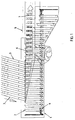
- Fig. 1 shows the device 1 having a number of removing members 2 being driven in a path along the feeding channels 3.
- the removing members 2 are mounted on coupling members 4, by which the removing members are connected to an endless conveyor 5 (see Fig. 3).
- the removed rows of products 6 are delivered to receiving members 7 by the removing members 2, said receiving members belonging to a conveyor belt system 8 situated in extension of the path portion of the removing members 2 along the feeding channels 3.
- Said conveyor belt system 8 can be part of a further processing device, such as e.g. a packaging device, or the products can be fed to a further processing device by said system.
- the removing members 2 are no longer in contact with the products, and they can be moved sidewards transverse to the driving direction, until - seen in vertical direction - they are entirely out of engagement with said conveyor belt system 8. From there, the path can bend downwards and return, in which the removing members can be returned in transverse direction. The latter can occur after the conveyor belt system has passed or, if possible, after the removing members have arrived at a height where they can return further underneath the conveyor belt system.
- Fig. 2 shows removing of the numbers of products 6 from the feeding channels 3 by the removing members 2 in more detail.
- the removing members 2 are mounted between two pairs rollers 9, 10 on the coupling members 4, as a result of which the removing members 2 can only move in their longitudinal direction.
- guiding elements 11 are provided at the upper side of the removing members, said guiding elements being intended for cooperation with a guide 12 (see Fig. 4).
- the movement made by the removing members 2 at the level of the feeding channels 3 is schematically indicated by the line 13. Due to this, the points of the removing members move in a direction perpendicular to the feeding channels 3, and are returned to the starting point of a next feed channel immediately after passing a feed channel.
- the products protrude over such a distance, that continually 4 products are taken away.
- the distance across which the fed row products protrudes is controlled with a feed stopping member 15 (see Fig. 4), and depends on the thickness of the individual products and the number of products to be accommodated in a row. Basically, with a certain product, always a fixed predetermined number of products will be removed from the feeding channels 3, which also results in a predetermined number per feeding channel 3. However, it is possible to change the adjustments of the stopping members between subsequent removals, as a result of which it is possible to vary the number of removed products and thus to prepare various roll lengths.
- the removing members 2 have at their carrying sides 18 a first portion 16 extending parallel to the feeding channels and by which the products are removed from the row. On passing a feeding channel, the number of removed products remains fixedly positioned in relation to the first portion 16.
- Lateral guides 14 for the removed products are mounted between the feeding channels 3, due to which a removing member 2 - before a next feeding channel 3 is reached - can be moved along the products with the first portion 16 without taking said products along. Owing to this, the first portion 16 will at the starting point of a next removal again be available for removing a next number of products.
- a lateral guide 14' is provided that will be contacted by the beginning of the row of removed products and which has an oblique course until just beyond the last feeding channel. Said guide 14' is adjusted to a certain desired length of a row of products to be removed, in which 14'' indicates a certain maximum length for a row of products to be removed.
- the first portion 16 is not allowed to protrude beyond the carrying side 18 of the removing member 2, since such a protruding portion, on lateral movement of the removing member 2 after delivering a row of products to a receiving member 7, might yet contact said row of removed products. Therefore, the first portion 16 is a recess in the removing member 2 returning to the carrying side 18 through a second portion 17.
- Fig. 3 shows a side view of the endless conveyor 5, which is preferably a chain, which is connected to the coupling members through arms 19.
- Parallel pairs of rollers 20, 21 enclosing respective guides 22, 23 are mounted on mounting plate 24 of said coupling members 4. Due to this, the path of the coupling members is completely set, and with it also the path of the removing members 2 being able to move only in one direction in relation to the coupling members.
- the guide 12 for the guiding elements 11 mounted on the removing members 2 is schematically illustrated with a dashed line in this figure.
- the conveyor belt system 8 with the receiving members is at a slightly lower level than the support plate 25 across which the products are moved by the removing members. Owing to this, the rows of products will come out of engagement with the removing members while being received in the receiving members 7. Receiving the rows of products takes place near the roller 26 of the conveyor belt system 8, whereupon the removing members can immediately be directed away from the conveyor belt system 8.
- the vertical distance across which the conveyor belt system extends in the example is relatively limited, and ends approximately at the top upper side of the chain wheel 27 for the endless chain 5. If no supports were mounted at the level of the removing device for the conveyor belt system, from this point the removing members can be returned to the starting position in which they arrive at the feeding channels 3. However, generally it will be preferred to execute the path symmetrical with a horizontal plane of symmetry, so that the required ground plane for the removing device in itself will remain as small as possible.
- Fig. 4 shows a cross-sectional view of the device in which the feed stopping member 15 is clearly illustrated.
- the products 6 are fed through the feeding channel 3, which is positioned on a vibrating table 29 here, and are stopped with the feed stopping member 15.
- the feed stopping member 15 is provided with a first plate portion 30 being connected to an arm portion 31, in which a recess 32 is mounted in the arm portion, said recess providing a passage for the removing members 2.
- the first plate portion may consist of a lower and an upper part situated respectively below and above said recess 32, or may consist of only one single part.
- the arm portion 31 is situated at one side of the fed products, so that at the other side, they are free to be taken along by the removing members.
- the feed stopping member 15 is movable, in the plane of the drawing to the left and the right, with the help of an operating member 34 and transmission 33. In this way, the number of products to be removed can be controlled.
Landscapes
- Engineering & Computer Science (AREA)
- Mechanical Engineering (AREA)
- Attitude Control For Articles On Conveyors (AREA)
Applications Claiming Priority (2)
| Application Number | Priority Date | Filing Date | Title |
|---|---|---|---|
| NL1006157A NL1006157C2 (nl) | 1997-05-29 | 1997-05-29 | Afneem- en inleginrichting voor hoogkant gepositioneerde platte produkten. |
| NL1006157 | 1997-05-29 |
Publications (1)
| Publication Number | Publication Date |
|---|---|
| EP0881176A1 true EP0881176A1 (de) | 1998-12-02 |
Family
ID=19765044
Family Applications (1)
| Application Number | Title | Priority Date | Filing Date |
|---|---|---|---|
| EP98201481A Withdrawn EP0881176A1 (de) | 1997-05-29 | 1998-05-14 | Vorrichtung zum Entfernen und Einfügen von flächigen Produkten in aufrechter Position |
Country Status (3)
| Country | Link |
|---|---|
| US (1) | US6158569A (de) |
| EP (1) | EP0881176A1 (de) |
| NL (1) | NL1006157C2 (de) |
Families Citing this family (2)
| Publication number | Priority date | Publication date | Assignee | Title |
|---|---|---|---|---|
| US6298975B1 (en) * | 2000-03-03 | 2001-10-09 | Mantissa Corporation | Lim sorting conveyor |
| AU2001243459A1 (en) * | 2000-03-09 | 2001-09-17 | The Web Access, Inc. | Method and apparatus for performing a research task by interchangeably utilizinga multitude of search methodologies |
Citations (4)
| Publication number | Priority date | Publication date | Assignee | Title |
|---|---|---|---|---|
| GB828618A (en) * | 1956-05-30 | 1960-02-17 | Hansel Junior Gmbh | Apparatus for packing piled-up tablets, as for instance biscuits, or chocolate bars |
| BE775189A (nl) * | 1970-11-11 | 1972-05-10 | Liga Fabrieken N V | Werkwijze en inrichting voor het stapsgewijze verzamelen van langs een aantal banen aangevoerde voorwerpen tot in een gemeenschappelijke afvoerbaan |
| CH521265A (de) * | 1970-01-05 | 1972-05-31 | Sig Schweiz Industrieges | Einrichtung zum Aufeinanderstapeln von flachen Gegenständen verschiedener Sorten, z.B. von Biskuits |
| GB2255544A (en) * | 1991-02-26 | 1992-11-11 | Gd Spa | Device for grouping flat products arranged side by side on edge. |
Family Cites Families (12)
| Publication number | Priority date | Publication date | Assignee | Title |
|---|---|---|---|---|
| US591801A (en) * | 1897-10-19 | Machine for folding and wrapping newspapers | ||
| DE521836C (de) * | 1929-07-09 | 1931-03-28 | Reinhold Hartmann | Ordnen, Abzaehlen und Zufuehren von Tabletten |
| US3054612A (en) * | 1960-01-18 | 1962-09-18 | Edward S Godlewski | Collating device |
| US3981394A (en) * | 1975-06-03 | 1976-09-21 | International Telephone And Telegraph Corporation | Feeding and assembly apparatus |
| GB1513861A (en) * | 1975-08-13 | 1978-06-14 | Burton S Gold Medal Biscuits | Assembling and packet-filling machine for biscuits |
| CH643197A5 (de) * | 1979-11-23 | 1984-05-30 | Sig Schweiz Industrieges | Verfahren und vorrichtung zur stapelung von scheibenfoermigen gegenstaenden. |
| US4304325A (en) * | 1980-02-28 | 1981-12-08 | Container Corporation Of America | Conveyor system and conveyor apparatus therefor |
| DE3444599A1 (de) * | 1984-12-07 | 1986-06-12 | Maschinenbau Gabler GmbH, 2400 Lübeck | Transport- und/oder stapelvorrichtung fuer formteile, insbesondere aus kunststoff oder auch aus blech |
| US4588179A (en) * | 1985-01-16 | 1986-05-13 | Thomas Gutierrez | Card collator with bottom hole pneumatic puller extractor |
| DE3702608C2 (de) * | 1987-01-29 | 1995-07-06 | Kolbus Gmbh & Co Kg | Zusammentragmaschine mit einer Einrichtung zum Vorbeschleunigen der Druckbogen |
| US4936077A (en) * | 1989-05-25 | 1990-06-26 | H. J. Langen & Sons Limited | Carton loading machine |
| US5775067A (en) * | 1997-01-08 | 1998-07-07 | Riverwood International Corporation | Article selector wedge |
-
1997
- 1997-05-29 NL NL1006157A patent/NL1006157C2/nl not_active IP Right Cessation
-
1998
- 1998-05-14 EP EP98201481A patent/EP0881176A1/de not_active Withdrawn
- 1998-05-20 US US09/081,652 patent/US6158569A/en not_active Expired - Fee Related
Patent Citations (4)
| Publication number | Priority date | Publication date | Assignee | Title |
|---|---|---|---|---|
| GB828618A (en) * | 1956-05-30 | 1960-02-17 | Hansel Junior Gmbh | Apparatus for packing piled-up tablets, as for instance biscuits, or chocolate bars |
| CH521265A (de) * | 1970-01-05 | 1972-05-31 | Sig Schweiz Industrieges | Einrichtung zum Aufeinanderstapeln von flachen Gegenständen verschiedener Sorten, z.B. von Biskuits |
| BE775189A (nl) * | 1970-11-11 | 1972-05-10 | Liga Fabrieken N V | Werkwijze en inrichting voor het stapsgewijze verzamelen van langs een aantal banen aangevoerde voorwerpen tot in een gemeenschappelijke afvoerbaan |
| GB2255544A (en) * | 1991-02-26 | 1992-11-11 | Gd Spa | Device for grouping flat products arranged side by side on edge. |
Also Published As
| Publication number | Publication date |
|---|---|
| NL1006157C2 (nl) | 1998-12-01 |
| US6158569A (en) | 2000-12-12 |
Similar Documents
| Publication | Publication Date | Title |
|---|---|---|
| US4413462A (en) | Accumulator and stacker for sandwiched biscuits and the like | |
| EP1764318B1 (de) | Zurückziehbare Übergabeeinrichtung für eine Dosiervorrichtung | |
| ATE141088T1 (de) | Einrichtung zum verteilen und sammeln von zu fördernden produkten | |
| US3979878A (en) | Container accumulating apparatus | |
| US4042100A (en) | Apparatus for arranging articles | |
| US4875571A (en) | Unloading method and apparatus for a cable finishing system | |
| US5450941A (en) | Apparatus for separating, conveying and grouping flat items | |
| EP0300530B1 (de) | Vorrichtung für die geordnete Zusammenstellung und Schaffung eines Sammelvorrats für konische Behälter in Verpackungsanlagen | |
| US2141212A (en) | Package collector | |
| EP0524606A1 (de) | Fluidum benutzende Vorrichtung zum Durchführen einer verschachtelten Ausrichtung von Gegenständen mit rundem Querschnitt | |
| EP1300351A1 (de) | Verfahren und Vorrichtung zum geordneten Abführen von ungeordnet zugeführten Produkten | |
| EP0881176A1 (de) | Vorrichtung zum Entfernen und Einfügen von flächigen Produkten in aufrechter Position | |
| US6966423B2 (en) | Station for connecting a packaging machine, in particular blistering machine, with a feeding line, leading to a boxing machine | |
| US5822969A (en) | Device for delivering wound bobbins from a textile machine | |
| SI9400125A (en) | Process and device for conveying articles, particulary for automatic packaging plants | |
| US3314213A (en) | Tray loading machine | |
| GB2267267A (en) | Method of separating two rows of cigarette packets | |
| EP1052200A1 (de) | Vorrichtung zur automatisierten Bildung von Behälter-Gruppen | |
| EP0686583A2 (de) | Steuervorrichtung für Produkte | |
| EP0161110B1 (de) | Vorrichtung zum Ordnen von Gegenständen in Gruppen | |
| EP0507413A1 (de) | Verteilerförderer | |
| IT8922698A1 (it) | Dispositivo orientatore e caricatore di fiale in genere, e di fiale-siringa in particolare | |
| US4244460A (en) | Process and equipment to form modules of biscuits or other like products | |
| EP0440848B1 (de) | Vorrichtung, um sich berührende Reihen von Lebensmitteln mit Zwischenraum anzuordnen, insbesondere Teekuchenscheiben, beim Verlassen eines Ofens auf einem Bandförderer | |
| EP0780329B1 (de) | Fördervorrichtung für Gegenstände |
Legal Events
| Date | Code | Title | Description |
|---|---|---|---|
| PUAI | Public reference made under article 153(3) epc to a published international application that has entered the european phase |
Free format text: ORIGINAL CODE: 0009012 |
|
| AK | Designated contracting states |
Kind code of ref document: A1 Designated state(s): BE CH DE ES FR GB IT LI NL SE |
|
| AX | Request for extension of the european patent |
Free format text: AL;LT;LV;MK;RO;SI |
|
| 17P | Request for examination filed |
Effective date: 19990518 |
|
| AKX | Designation fees paid |
Free format text: BE CH DE ES FR GB IT LI NL SE |
|
| 17Q | First examination report despatched |
Effective date: 20000223 |
|
| STAA | Information on the status of an ep patent application or granted ep patent |
Free format text: STATUS: THE APPLICATION IS DEEMED TO BE WITHDRAWN |
|
| 18D | Application deemed to be withdrawn |
Effective date: 20011101 |