EP0881365A2 - Brennkraftmaschinenkonstruktion - Google Patents
Brennkraftmaschinenkonstruktion Download PDFInfo
- Publication number
- EP0881365A2 EP0881365A2 EP98830316A EP98830316A EP0881365A2 EP 0881365 A2 EP0881365 A2 EP 0881365A2 EP 98830316 A EP98830316 A EP 98830316A EP 98830316 A EP98830316 A EP 98830316A EP 0881365 A2 EP0881365 A2 EP 0881365A2
- Authority
- EP
- European Patent Office
- Prior art keywords
- engine
- structure according
- lubricating fluid
- engine block
- gear wheel
- Prior art date
- Legal status (The legal status is an assumption and is not a legal conclusion. Google has not performed a legal analysis and makes no representation as to the accuracy of the status listed.)
- Granted
Links
Images

Classifications
-
- F—MECHANICAL ENGINEERING; LIGHTING; HEATING; WEAPONS; BLASTING
- F02—COMBUSTION ENGINES; HOT-GAS OR COMBUSTION-PRODUCT ENGINE PLANTS
- F02B—INTERNAL-COMBUSTION PISTON ENGINES; COMBUSTION ENGINES IN GENERAL
- F02B67/00—Engines characterised by the arrangement of auxiliary apparatus not being otherwise provided for, e.g. the apparatus having different functions; Driving auxiliary apparatus from engines, not otherwise provided for
- F02B67/04—Engines characterised by the arrangement of auxiliary apparatus not being otherwise provided for, e.g. the apparatus having different functions; Driving auxiliary apparatus from engines, not otherwise provided for of mechanically-driven auxiliary apparatus
-
- F—MECHANICAL ENGINEERING; LIGHTING; HEATING; WEAPONS; BLASTING
- F01—MACHINES OR ENGINES IN GENERAL; ENGINE PLANTS IN GENERAL; STEAM ENGINES
- F01M—LUBRICATING OF MACHINES OR ENGINES IN GENERAL; LUBRICATING INTERNAL COMBUSTION ENGINES; CRANKCASE VENTILATING
- F01M1/00—Pressure lubrication
- F01M1/02—Pressure lubrication using lubricating pumps
Definitions
- the present invention relates to an engine structure for internal combustion engines.
- engine structure is used to mean the assembly consisting of the engine block and crankcase and the built-in auxiliary services driven by the engine, in particular, the lubricating pump and the suction unit, that is, a device designed to continuously generate a vacuum in a chamber connected to the auxiliary services which require negative pressure for their operation, such as, for example, the brake system of modern cars.
- auxiliary services are separate from the engine block and are driven through transmission belts.
- the aim of the present invention is to overcome the disadvantages mentioned above by providing an engine structure that utilizes existing space and does not therefore increase the overall dimensions of the engine.
- One aspect of the present invention is to provide an engine structure that comprises an engine block, a crankshaft with at least one first gear wheel keyed to it, means for creating suction and means for distributing lubricating fluid under pressure and where the first gear wheel meshes with a second gear wheel that directly drives the means for creating suction and with a third gear wheel that drives the means for distributing lubricating fluid under pressure.
- Another aspect of the present invention is to provide an engine structure that comprises an engine block, a crankshaft with at least one first gear wheel keyed to it and auxiliary means for creating suction or for distributing lubricating fluid under pressure and where the engine block has at least one hollow to house said auxiliary means.
- a further aspect of the present invention is to provide an engine structure that comprises an engine block, a crankshaft with at least one first gear wheel keyed to it, means for creating suction and means for distributing lubricating fluid under pressure through suitable supply and delivery ducts and where at least one of these ducts lies mainly outside the engine block.
- Yet another aspect of the present invention is to provide an engine structure that comprises an engine block, a crankshaft with at least one first gear wheel keyed to it and consisting of a cup gear which provides enough space for an oil seal without increasing the overall dimensions.
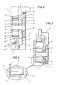
- the numeral 1 indicates an internal combustion engine block from which the end of a crankshaft 2 protrudes, the latter having keyed to it a first cup-shaped gear wheel 3, that is to say, a gear wheel whose teeth 4 lie in a plane that is axially offset with respect to the wheel hub 5 (see Figure 2) in such a way as to create the space necessary for the ideal positioning of an oil seal 40 without increasing the overall dimensions of the gear.
- the first gear wheel 3 (not illustrated in this Figure) meshes with a second gear wheel 6 keyed to the shaft 7 of a rotor 8 of a suction unit 9 designed to generate a vacuum, for example for the brake system of a motor vehicle.
- the suction unit 9 is mounted inside a first box-shaped element 11, located in a first hollow 10, preferably blind, made in the engine block 1.
- the end wall 12 of the first hollow 10 is used as a reference for locating the box-shaped element 11 in which the suction unit 9 is fitted. In this way, the clearance between the rotor 8 of the suction unit and the end wall 12 of the first hollow 10 is reduced to a minimum, depending solely on the tolerances T of the first box-shaped element 11 and that of the rotor 8 (since the first box-shaped element 11 is always in contact with the end wall 12 of the hollow 10, as can be seen in Figure 4).
- the first gear wheel 3 also meshes with a third gear wheel 13 (see Figure 2) keyed to the shaft 14 of the rotor 19 of a lubricating pump 15.
- the pump 15 is mounted inside a second box-shaped element 17 located in a second blind hollow 16 made in the engine block 1.
- the end wall 18 of the second hollow 16 is used as a reference for locating the box-shaped element 17 in which the pump 15 is fitted.
- the clearance between the rotor 19 of the pump 15 and the end wall 18 of the second hollow 16 is reduced to a minimum, depending, in this case too, solely on the tolerances between the depth of the second box-shaped element 17 and that of the rotor 19.
- the second box-shaped element 17 comprises a cover 21 that protrudes from said second hollow 16 and that has made in it a first chamber 22 into which the supply duct 23 of the pump 15 leads, in the direction of the arrows F (a part of the supply duct is illustrated in Figures 1 and 2) and a second chamber 24 from which the delivery duct 25 of the pump 15 branches (the connecting port of the delivery duct is illustrated in Figure 1).
- first chamber 22 and the second chamber 24 are made around the bearing S of a shaft which mounts the third gear wheel 13 and have the same width as the bearing so as not to increase the overall dimensions of the unit.
- the supply duct 23 and the delivery duct 25 of the engine block 1 communicate with the cover 21 of the box-shaped element 17 through corresponding connecting ducts 23' and 25' (partly illustrated in Figure 1) which lie mainly on the outside of the engine block 1, thus eliminating the need to make the ducts entirely in the engine block 1 using complicated and costly processes.
- the connecting ducts 23' and 25' connect with corresponding ports (not illustrated) made in the engine block 1 and which, after the second box-shaped element 17 has been fitted, lead into the corresponding first and second chambers 22 and 24 in the second box shaped element 17 itself.
- the engine block 1 has made in it the first and second hollows 12 and 16 to house the corresponding box shaped elements 11 and 17 each of which has its own fluid supply and delivery ducts.
- the suction unit 9 is supplied with oil from the engine sump (not illustrated) so that the rotor 8 can be lubricated through a first duct 41 that leads into the area labelled 41' in Figure 3.
- the rotor 8 creates a vacuum in a second suction duct 42 which communicates with the related service tank.
- the delivery of the rotor 8, which consists of air mixed with oil, is in turn supplied to a third duct 43 made in the front wall of the first box-shaped element 11 and from here, the mixture is fed back into the engine sump and recycled.
- the three ducts 41, 42 and 43 of the suction unit 9 are made in and lie entirely inside the engine block 1 which, once these elements have been assembled, is closed by a simple guard, labelled C in the accompanying drawings, without necessitating special machine processes or sealing elements and thereby also reducing the axial dimensions of the engine block 1 as a whole.
- the valve 26 is designed to enable a part of the fluid delivered by the pump 15 to the delivery duct 25 to be diverted directly into the supply duct 23 through the bypass duct 27 when the delivery pressure of the pump 15 exceeds a preset value.
- the regulating valve 26 consists of a shutter element 30, preferably cylindrical, fitted in a first section 28 of the bypass duct 27. At a first end of it, the shutter element 30 communicates with the delivery duct 25 of the pump 15 and, close to a second end, it has a plurality of radial holes 31.
- the second end of the cylindrical element 30 has a shutting element 32 pushed by a spring 33 that is preloaded by a preset, adjustable value, the spring having one end resting against the shutting element 32 and the other end resting against a stop element 34.
- the spring 33 and the shutting element 32 are positioned inside a second section 29 of the bypass duct that is larger in diameter than the first section 28 and that communicates with the suction duct 23 of the pump 15.
Landscapes
- Engineering & Computer Science (AREA)
- Mechanical Engineering (AREA)
- General Engineering & Computer Science (AREA)
- Chemical & Material Sciences (AREA)
- Combustion & Propulsion (AREA)
- Lubrication Of Internal Combustion Engines (AREA)
- Cylinder Crankcases Of Internal Combustion Engines (AREA)
- Control Of Throttle Valves Provided In The Intake System Or In The Exhaust System (AREA)
Applications Claiming Priority (2)
| Application Number | Priority Date | Filing Date | Title |
|---|---|---|---|
| IT97BO000326A IT1292591B1 (it) | 1997-05-30 | 1997-05-30 | Struttura di motore per motori a combustione interna. |
| ITBO970326 | 1997-05-30 |
Publications (3)
| Publication Number | Publication Date |
|---|---|
| EP0881365A2 true EP0881365A2 (de) | 1998-12-02 |
| EP0881365A3 EP0881365A3 (de) | 1999-06-09 |
| EP0881365B1 EP0881365B1 (de) | 2003-04-09 |
Family
ID=11342302
Family Applications (1)
| Application Number | Title | Priority Date | Filing Date |
|---|---|---|---|
| EP98830316A Expired - Lifetime EP0881365B1 (de) | 1997-05-30 | 1998-05-21 | Brennkraftmaschinenkonstruktion |
Country Status (4)
| Country | Link |
|---|---|
| EP (1) | EP0881365B1 (de) |
| AT (1) | ATE237071T1 (de) |
| DE (1) | DE69813077D1 (de) |
| IT (1) | IT1292591B1 (de) |
Families Citing this family (1)
| Publication number | Priority date | Publication date | Assignee | Title |
|---|---|---|---|---|
| US9435290B2 (en) | 2014-08-04 | 2016-09-06 | Achates Power, Inc. | Opposed-piston engine structure with a split cylinder block |
Family Cites Families (7)
| Publication number | Priority date | Publication date | Assignee | Title |
|---|---|---|---|---|
| GB807325A (en) * | 1956-06-05 | 1959-01-14 | Fiat Spa | Device for transferring oil from a stationary pipe to passages machined inside a rotating crankshaft |
| DE2833167A1 (de) * | 1978-07-28 | 1980-02-14 | Barmag Barmer Maschf | Baueinheit, bestehend aus einer oelpumpe zur oelumlaufschmierung einer brennkraftmaschine und einer vakuumpumpe zur erzeugung eines vakuums fuer die bremskraftverstaerkung in kraftfahrzeugen |
| AT388777B (de) * | 1980-11-27 | 1989-08-25 | List Hans | Brennkraftmaschine |
| US4586468A (en) * | 1984-10-05 | 1986-05-06 | General Motors Corporation | Tandem pump assembly |
| IT208998Z2 (it) * | 1986-12-23 | 1988-09-02 | Fiat Auto Spa | Dispositivo di comando per una pompa olio in un motore a combustione interna |
| JPS648314A (en) * | 1987-06-30 | 1989-01-12 | Aisin Seiki | Cooling and lubricating device for internal combustion engine |
| DE3729603A1 (de) * | 1987-09-04 | 1989-03-16 | Porsche Ag | Schmiervorrichtung fuer einen hubkolbenmotor |
-
1997
- 1997-05-30 IT IT97BO000326A patent/IT1292591B1/it active IP Right Grant
-
1998
- 1998-05-21 DE DE69813077T patent/DE69813077D1/de not_active Expired - Lifetime
- 1998-05-21 AT AT98830316T patent/ATE237071T1/de not_active IP Right Cessation
- 1998-05-21 EP EP98830316A patent/EP0881365B1/de not_active Expired - Lifetime
Also Published As
| Publication number | Publication date |
|---|---|
| ATE237071T1 (de) | 2003-04-15 |
| ITBO970326A0 (it) | 1997-05-30 |
| ITBO970326A1 (it) | 1998-11-30 |
| IT1292591B1 (it) | 1999-02-08 |
| EP0881365B1 (de) | 2003-04-09 |
| DE69813077D1 (de) | 2003-05-15 |
| EP0881365A3 (de) | 1999-06-09 |
Similar Documents
| Publication | Publication Date | Title |
|---|---|---|
| US7174998B2 (en) | Submerged electric fluid pump | |
| US7967580B2 (en) | Oil pump for an internal combustion engine | |
| EP2005003B1 (de) | Verbesserte vakuumpumpe | |
| US5645406A (en) | Transmission assembly with positive-displacement pump with suction throttle driven by a hydrodynamic converter | |
| EP0779127A1 (de) | Schleifspindel mit hydrostatischer Lagerung | |
| EP1243794B1 (de) | Hydraulischer Drehflügelzellenmotor | |
| JP3380548B2 (ja) | 車輌機関の液圧ポンプ | |
| US5823750A (en) | Housing arrangement for an external rotar driven lubricating pump | |
| EP0059086A1 (de) | Rotierende Hilfsgeräte für Brennkraftmaschinen | |
| GB2205611A (en) | A pump assembly | |
| US6848412B2 (en) | Internal combustion engine | |
| EP2745016B1 (de) | Verbesserte vakuumpumpe | |
| US4428195A (en) | Rotary vacuum pump | |
| SK329192A3 (en) | Motor with internal combustion and with pump located on camshaft | |
| US20060213477A1 (en) | Pump combination | |
| US5421702A (en) | Lubricant pump for a turbine | |
| EP0543601A2 (de) | Rotierende Geräte | |
| JP4119215B2 (ja) | オイルの受け渡し構造 | |
| EP0881365A2 (de) | Brennkraftmaschinenkonstruktion | |
| US5549452A (en) | Double pump | |
| EP1800017B1 (de) | Kupplung | |
| US4826410A (en) | Cooling systems for rotary piston engines | |
| US4096693A (en) | Torque converter fluid control system for power transmission system | |
| EP0035891A1 (de) | Stirnseitenabdichtungssystem | |
| US3560120A (en) | Rotary compressor |
Legal Events
| Date | Code | Title | Description |
|---|---|---|---|
| PUAI | Public reference made under article 153(3) epc to a published international application that has entered the european phase |
Free format text: ORIGINAL CODE: 0009012 |
|
| AK | Designated contracting states |
Kind code of ref document: A2 Designated state(s): AT DE ES FR GB IT |
|
| AX | Request for extension of the european patent |
Free format text: AL;LT;LV;MK;RO;SI |
|
| PUAL | Search report despatched |
Free format text: ORIGINAL CODE: 0009013 |
|
| AK | Designated contracting states |
Kind code of ref document: A3 Designated state(s): AT BE CH CY DE DK ES FI FR GB GR IE IT LI LU MC NL PT SE |
|
| AX | Request for extension of the european patent |
Free format text: AL;LT;LV;MK;RO;SI |
|
| 17P | Request for examination filed |
Effective date: 19990915 |
|
| AKX | Designation fees paid |
Free format text: AT DE ES FR GB IT |
|
| 17Q | First examination report despatched |
Effective date: 20010629 |
|
| GRAH | Despatch of communication of intention to grant a patent |
Free format text: ORIGINAL CODE: EPIDOS IGRA |
|
| GRAH | Despatch of communication of intention to grant a patent |
Free format text: ORIGINAL CODE: EPIDOS IGRA |
|
| GRAA | (expected) grant |
Free format text: ORIGINAL CODE: 0009210 |
|
| AK | Designated contracting states |
Designated state(s): AT DE ES FR GB IT |
|
| PG25 | Lapsed in a contracting state [announced via postgrant information from national office to epo] |
Ref country code: FR Free format text: LAPSE BECAUSE OF FAILURE TO SUBMIT A TRANSLATION OF THE DESCRIPTION OR TO PAY THE FEE WITHIN THE PRESCRIBED TIME-LIMIT Effective date: 20030409 Ref country code: AT Free format text: LAPSE BECAUSE OF FAILURE TO SUBMIT A TRANSLATION OF THE DESCRIPTION OR TO PAY THE FEE WITHIN THE PRESCRIBED TIME-LIMIT Effective date: 20030409 |
|
| REG | Reference to a national code |
Ref country code: GB Ref legal event code: FG4D |
|
| PG25 | Lapsed in a contracting state [announced via postgrant information from national office to epo] |
Ref country code: GB Free format text: LAPSE BECAUSE OF NON-PAYMENT OF DUE FEES Effective date: 20030709 |
|
| PG25 | Lapsed in a contracting state [announced via postgrant information from national office to epo] |
Ref country code: DE Free format text: LAPSE BECAUSE OF FAILURE TO SUBMIT A TRANSLATION OF THE DESCRIPTION OR TO PAY THE FEE WITHIN THE PRESCRIBED TIME-LIMIT Effective date: 20030710 |
|
| PG25 | Lapsed in a contracting state [announced via postgrant information from national office to epo] |
Ref country code: ES Free format text: LAPSE BECAUSE OF FAILURE TO SUBMIT A TRANSLATION OF THE DESCRIPTION OR TO PAY THE FEE WITHIN THE PRESCRIBED TIME-LIMIT Effective date: 20031030 |
|
| PLBE | No opposition filed within time limit |
Free format text: ORIGINAL CODE: 0009261 |
|
| STAA | Information on the status of an ep patent application or granted ep patent |
Free format text: STATUS: NO OPPOSITION FILED WITHIN TIME LIMIT |
|
| GBPC | Gb: european patent ceased through non-payment of renewal fee |
Effective date: 20030709 |
|
| EN | Fr: translation not filed | ||
| 26N | No opposition filed |
Effective date: 20040112 |
|
| PGFP | Annual fee paid to national office [announced via postgrant information from national office to epo] |
Ref country code: IT Payment date: 20140527 Year of fee payment: 17 |
|
| PG25 | Lapsed in a contracting state [announced via postgrant information from national office to epo] |
Ref country code: IT Free format text: LAPSE BECAUSE OF NON-PAYMENT OF DUE FEES Effective date: 20150521 |