EP0881374A2 - Pneumatischer Zustandschätzer für Brennkraftmaschine - Google Patents
Pneumatischer Zustandschätzer für Brennkraftmaschine Download PDFInfo
- Publication number
- EP0881374A2 EP0881374A2 EP98201351A EP98201351A EP0881374A2 EP 0881374 A2 EP0881374 A2 EP 0881374A2 EP 98201351 A EP98201351 A EP 98201351A EP 98201351 A EP98201351 A EP 98201351A EP 0881374 A2 EP0881374 A2 EP 0881374A2
- Authority
- EP
- European Patent Office
- Prior art keywords
- pressure
- gas flow
- pneumatic
- node
- engine system
- Prior art date
- Legal status (The legal status is an assumption and is not a legal conclusion. Google has not performed a legal analysis and makes no representation as to the accuracy of the status listed.)
- Granted
Links
Images


Classifications
-
- F—MECHANICAL ENGINEERING; LIGHTING; HEATING; WEAPONS; BLASTING
- F02—COMBUSTION ENGINES; HOT-GAS OR COMBUSTION-PRODUCT ENGINE PLANTS
- F02D—CONTROLLING COMBUSTION ENGINES
- F02D41/00—Electrical control of supply of combustible mixture or its constituents
- F02D41/02—Circuit arrangements for generating control signals
- F02D41/14—Introducing closed-loop corrections
- F02D41/1401—Introducing closed-loop corrections characterised by the control or regulation method
-
- F—MECHANICAL ENGINEERING; LIGHTING; HEATING; WEAPONS; BLASTING
- F02—COMBUSTION ENGINES; HOT-GAS OR COMBUSTION-PRODUCT ENGINE PLANTS
- F02D—CONTROLLING COMBUSTION ENGINES
- F02D41/00—Electrical control of supply of combustible mixture or its constituents
- F02D41/02—Circuit arrangements for generating control signals
- F02D41/14—Introducing closed-loop corrections
- F02D41/1401—Introducing closed-loop corrections characterised by the control or regulation method
- F02D2041/1413—Controller structures or design
- F02D2041/1425—Controller structures or design using a bond graph model or models with nodes
-
- F—MECHANICAL ENGINEERING; LIGHTING; HEATING; WEAPONS; BLASTING
- F02—COMBUSTION ENGINES; HOT-GAS OR COMBUSTION-PRODUCT ENGINE PLANTS
- F02D—CONTROLLING COMBUSTION ENGINES
- F02D41/00—Electrical control of supply of combustible mixture or its constituents
- F02D41/02—Circuit arrangements for generating control signals
- F02D41/14—Introducing closed-loop corrections
- F02D41/1401—Introducing closed-loop corrections characterised by the control or regulation method
- F02D2041/1433—Introducing closed-loop corrections characterised by the control or regulation method using a model or simulation of the system
Definitions
- This invention relates to internal combustion engine pneumatic state estimation and, more particularly, to pneumatic state estimation and correction for engine system control and diagnostics.
- estimation accuracy may not be valid throughout a period of operation of an engine system, leading to reduced estimation accuracy.
- the estimation is repeated during an engine system operating cycle to maintain current pressure and flow rate information throughout the network and may include several throughput intensive operations, such as numerical integration operations.
- certain compromises may be required so that the estimation may be implemented in a controller having throughput limitations and having various other control, maintenance and diagnostic responsibilities.
- a relatively granular estimation iteration rate may be required so as to not overwhelm controller throughput.
- Estimation stability may be compromised under certain operating conditions with such an iteration rate, leading to reduced estimation accuracy under such operating conditions.
- Any reduction in estimation accuracy may result in an inconsistency in the flow estimation of the network.
- reduced estimation accuracy may lead to an imbalance in net flow at a node of the network in which net flow into the node deviates in an unexpected manner from net flow out of the node.
- Such an inconsistency can lead to reduced engine system control and diagnostic accuracy.
- the present invention is directed to estimating pneumatic states within an engine system reticulated into a flow network for engine control and diagnostic procedures wherein pneumatic state estimation information is applied to resolve inconsistencies within the network to improve overall estimation accuracy and increase engine system control and diagnostic precision.
- a sequence of interdependent gas flow rate estimation operations are periodically carried out during an engine system operating cycle for various flow paths within an engine system.
- the resulting flow rate estimations are applied to a conservation of flow model to identify deviations in net flow away from an expected net flow of at least one node of the reticulated network. Weaknesses in the estimation approach are identified and attributed to any identified deviation. The gas flow error corresponding to such weaknesses in the estimation approach are gradually corrected as a function of the identified deviation to minimize any flow error, to preserve engine control and diagnostic precision.
- a node of the reticulated engine system such as in the engine intake or exhaust manifold, is identified and all pneumatic states that significantly directly or indirectly affect gas flow through the identified node are estimated through application of a pneumatic state estimation approach.
- a pneumatic state estimation approach Under certain operating conditions, such as steady state operating conditions characterized by substantially no gas filling or depletion at the node, at which point dynamic estimation is no longer required, net gas flow at the identified node is calculated by combining all estimated pneumatic states for the node. If the net gas flow deviates from an expected net flow, such as zero net flow under steady state operating conditions, an estimation error is assumed to be present. A correction is made to an identified weakness in the estimation approach as a function of the determined net gas flow deviation.
- the identified node is within the engine intake manifold and the corresponding model weakness is, under certain operating conditions, a prior estimate of atmospheric (barometric) pressure.
- the gas flow deviation in the intake manifold node is applied to correct the prior atmospheric pressure estimate.
- Cost and inconvenience associated with expensive barometric pressure sensing hardware and calibration procedures, including burdensome procedures to calibrate the effects of change in barometric pressure at various altitudes, are thereby avoided.
- the identified node is within the engine exhaust manifold. Pneumatic state estimation instability under certain operating conditions at such node leads to state estimation error which is gradually reduced toward zero as a function of an identified deviation in net flow in the exhaust manifold. The resulting gains in stability allow for application of numerically intensive estimation procedures in practical controller-based systems having significant throughput constraints.
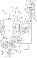
- FIG. 1 a conventional internal combustion engine system is illustrated to which control and diagnostic operations are applied in accordance with this embodiment.
- the engine system is reticulated into an interdependent network of gas mass flows designated by arrows labeled as F 1 - F 16 between a network of pneumatic volume nodes designated as N1 - N7 .
- Inlet air at atmospheric pressure at node N1 passes through fresh air inlet 11 through air cleaner 13 and into intake duct 15 at node N2 .
- the inlet air is drawn across through throttle body 17 in which is rotatably disposed an inlet air valve 19 in the form of a throttle plate the position of which is manually or electronically controlled to vary restriction to inlet air passing through the throttle body and into intake duct 21 for passage into intake manifold 23 at node N3 .
- a conventional pressure transducer 24 is exposed to gas pressure in the intake manifold 23 and transduces such pressure into output signal MAP.
- Each cylinder, such as cylinder 30, includes a combustion chamber, such as combustion chamber 31 and a crankcase, such as crankcase 33, separated by a piston, such as piston 34 which substantially sealingly engages the wall of the cylinder 30.
- a quantity of fuel is injected, via conventional fuel injector 87, in response to a fuel injection command signal applied thereto, into the intake runner 25 for mixing with the inlet air, wherein the resulting mixture is drawn into the combustion chamber 31 during a cylinder intake event during which an intake valve 26 is driven to an open position and during which a low pressure condition is present in the combustion chamber 31.
- the air-fuel mixture is ignited in the combustion chamber 31 during a combustion event initiated by a timed ignition arc driven across the spaced electrodes of spark plug 32 which extends into the combustion chamber 31.
- the piston 34 within the cylinder 30 is reciprocally driven under the effective pressure of the combustion event for driving vehicle wheels, accessory loads, etc., as is generally understood in the art.
- Gasses produced in the combustion process within the combustion chamber 31 are exhausted from the combustion chamber 31 during a cylinder exhaust event and through exhaust runner 27 to exhaust manifold 29 at node N5 .
- the exhaust gasses pass through the exhaust manifold 29 to exhaust duct 35 leading to catalytic treatment device and muffler (generally illustrated as element 37) and then to the atmosphere at the pressure of node N1 .
- Vacuum is selectively applied to the cylinder crankcase 33 at node N4 through a positive crankcase ventilation (PCV) conduit 49 including a standard PCV valve 51, the PCV conduit being connected between the crankcase 33 and the intake duct 21, the vacuum for drawing blow-by gasses that have been driven from the cylinder combustion chamber 31 to the crankcase 33 under the pressure of the combustion process.
- a supply of fresh inlet air from node N2 is provided to the crankcase 33 via a fresh air conduit 63 connected between the intake duct 15 and the crankcase 33.
- the PCV valve selectively draws the blow-by gasses from the crankcase for mixing with intake air for consumption in engine cylinders for purifying engine system lubricants.
- a portion of the exhaust gasses are drawn from the exhaust manifold 29 at node N5 through an exhaust gas recirculation (EGR) conduit 43 and across an EGR valve 41 of the electrical solenoid type responsive to an EGR control signal on line 83 and further through a conduit 45 into the intake manifold 23 at node N3 for mixing with inlet air for delivery to the engine cylinder combustion chambers.
- the state of the EGR valve is controlled electronically as is generally understood in the art in response to general operating conditions to vary the dilution of the fresh inlet air with substantially inert exhaust gas to provide for a reduction in the engine emissions component of oxides of nitrogen (NOx).
- NOx oxides of nitrogen
- a portion of inlet air is routed through conduits 59 and 61 having a conventional idle air bypass valve 60 therebetween of the solenoid type responsive to an idle air command signal on line 81, for bypassing the restriction of the inlet air valve 19 within the throttle body 17 under certain generally-known control conditions such as idle operating conditions in which precise control of relatively low fresh air flow rates is required.
- Brake boost conduit 47 of any conventional type opens into intake manifold 23 at node N3 providing for a minor gas flow F 16 during application of a conventional service brake pedal of an automotive vehicle (not shown) as is well-known in the art.
- Vehicles equipped with well-known evaporative emission controls may also have gas flow through a canister purge valve 53 and canister purge conduits 55 and 57 into throttle body 17 downstream, according to the normal direction of flow through the throttle body 17, of the inlet air valve 19 with the actual effective flow into intake manifold at node N3 .
- Charcoal canister 65 generally releases fuel vapors when fresh air is drawn through purge vent 67 and purge vent conduits 69 and 71.
- Fuel tank 75 may also release fuel vapors which may be absorbed in canister 65, may be released thereby, or may pass directly to the engine along with released fuel vapors through conduit 55 at node N6 for consumption in the described cylinder combustion process.
- Fuel tank 75 having a supply of fuel therein at node N7 may include a leak orifice 76 through which fresh air may enter the fuel tank.
- Conventional pressure transducer 78 is disposed within the fuel tank 75 for transducing vapor pressure within the tank into an out output signal FP.
- Fuel vapor passes from the fuel tank 75 through a conventional rollover orifice 92 and to the canister 65 via tank vapor recovery conduit 73.
- flow paths including flow path F 1 across the air cleaner 13 between nodes N1 and N2 , flow path F 2 along PCV fresh air conduit 63 between nodes N2 and N4 , flow path F 3 through throttle body 17 across the inlet air valve 19 from node N2 to intake duct 21, flow path F 4 through idle air bypass conduits 59 and 61, flow path F 5 through the intake runner 25 between node N3 and the cylinder combustion chamber 31, flow path F 6 between the combustion chamber and the crankcase (node N4 ) of an engine cylinder 30, flow path F 7 to the atmosphere at node N1 through catalytic treatment device and muffler elements 37 and exhaust ducts 35 and 39, flow path F 8 through EGR conduits 43 and 45 between node N5 and the EGR valve 41, flow path F 9 through the PCV conduit 49 between node N4 and the intake duct 21 (effectively at node N3 ), flow path F 10 through the conduit 55 between node N6 and the throttle body 17 (effectively at
- a general diagram illustrating engine system control and diagnostics includes an engine system 210, such as the engine system of FIG. 1 having various parameters transduced by various conventional sensors 212 into signals applied to a controller 214 which carries out a sequence of state estimation operations for estimating pressures of interest at certain of the nodes of FIG. 1, such as at nodes N3 , N5 , N6 , and N7 in this embodiment and for determining mass flow rates at certain of the flow branches of FIG. 1, such as flow branches F 3 , F 4 , F 5 , F 7 , F 8 , F 10 , F 11 , F 12 , F 13 and F 15 in this embodiment.
- a state model 218 for modeling such pressures and flows is included with the state estimator 216.
- Pressure and flow outputs are provided from the state estimator 216 to various controls 220, for example for controlling engine fueling, inlet air rate, EGR rate, and to various diagnostic procedures 222 for diagnosing certain engine control systems using the pressure and flow information.
- the controls 220 issue control signals to drive various engine system control actuators 226, such as fuel injectors 87 (FIG. 1), air control valves 19 and 60 (FIG. 1), EGR valve 41, etc. in accordance with generally available control strategies. Manual operator inputs may further be applied to such actuators, as is generally understood in the art.
- the diagnostics 222 interact with the controls according to standard control and diagnostic procedures and may provide diagnostic information to various conventional indicators 224, such as lamps or chimes.
- the controller 214 takes the form of a conventional single-chip microcontroller in this embodiment including such conventional elements as a central processing unit, an input-output unit, and memory devices including random access memory RAM devices, read only memory ROM devices and other standard elements.
- FIGS. 3 and 4 flow diagrams for illustrating a flow of start-up operations and control and diagnostic operations for carrying out the estimation and correction operations of this embodiment detail, in a step by step manner, processes carried out by the controller 214 of FIG. 2 and implemented in the form of a set of instructions stored in a ROM device of the controller.
- the operations provide for estimation of pressure at nodes N3 , N5 , N6 and N7 of FIG. 1 through estimation of mass flow into and out of such nodes, and for estimation and correction of certain pressures, including barometric pressure at node N1 when contradictory flow information at a node is identified.
- the flow and pressure information is then applied in general engine system control and diagnostic operations.
- FIG. 3 upon application of ignition power to the controller of FIG. 2 at the start of an engine system ignition cycle, such as when an engine system operator rotates an ignition cylinder to an "on" position, the operations of FIG. 3 are initiated beginning at a step 300 and proceed to a next step 302 at which signal MAP from the transducer 24 of FIG. 1 is sampled as an indication of the present gas pressure in the intake manifold 23 of FIG. 1 and signal FP from transducer 78 of FIG. 1 is sampled as an indication of the present fuel tank 75 (FIG. 1) vapor pressure.
- P em (t) is estimated exhaust manifold pressure at node N5 at time t
- P ec (t) is estimated evaporative canister 65 (FIG. 1) pressure at node N6 at time t
- P ft (t) is estimated fuel tank pressure at node N7 (FIG. 1) at time t
- f thr (t) is gas flow rate across the air valve 19 of FIG. 1 (flow branch F 3 ) at time t
- f iac (t) is gas flow rate across the bypass valve 60 of FIG. 1 (flow branch F 4 ) at time t
- f egr (t) is gas flow rate through the EGR conduit 43 of FIG.
- f eng (t) is gas flow through the engine cylinder intake runner 25 of FIG. 1 (flow branch F 5 ) at time t
- f exh (t) is gas flow through exhaust duct 35 of FIG. 1 (flow branch F 7 ) at time t
- f prg (t) is gas flow across the purge valve 53 of FIG. 1 (flow branch F 10 ) at time t
- f rol (t) is gas flow across the rollover orifice 92 of FIG. 1 (flow branch F 12 ) at time t
- f lv (t) is gas vaporization and leak flow within the fuel tank 75 of FIG.
- f vnt (t) is gas flow through the purge vent valve 67 of FIG. 1 (flow branch F 13 ) at time t, and wherein t is currently set to zero (at engine system startup).
- any required general initialization operations are next carried out at a step 308 including such well-known startup operations as operations to clear memory locations, to transfer data and program instructions from ROM devices to RAM devices, and to set pointers, counters and constants to initial values. It should be pointed out that the operations of step 308 may be required to be carried out prior to the step 304.
- Numerous time and event based interrupts are next enabled at a step 310 to occur following certain time intervals, or following certain engine system events such as cylinder top dead center events whereby interrupt service operations are carried out following such interrupts to provide for synchronous and asynchronous engine system control, diagnostic and maintenance operations.
- Background operations are then carried out at a next step 312 including general, low priority maintenance and diagnostic operations, including operations to diagnose the engine system through application of the pneumatic state estimation information provided by the state estimator 216 of FIG. 2.
- a series of operations for servicing an interrupt which, in this embodiment is a standard timer-based interrupt but which may alternatively be an event-based interrupt, for example following engine cylinder top dead center events, are detailed in a step by step manner for execution following occurrence of an interrupt enabled at the described step 310 of FIG. 3.
- such timer-based interrupt is set up to occur approximately every five to ten milliseconds while the controller 214 of FIG. 2 is manually activated by an engine system operator.
- the series of operations begin, following each such interrupt occurrence, after temporarily suspending any ongoing controller operations of lower priority in a pre-established priority hierarchy, at a step 400 and proceed to sample input signals at a next step 402, including signals MAP, TP, RPM, and FP of FIG.
- Temperature estimation operations are next carried out at a step 404, including operations for directly measuring or estimating gas temperature at various nodes within the engine system of FIG. 1, including at nodes N1 , N3 , N5 , N6 , and N7 of FIG. 1.
- the temperature estimation operations described in the disclosure of copending U.S. patent application serial number , attorney docket number H-197436, filed May 22, 1997, assigned to the assignee of this application and hereby incorporated herein by reference may be carried out at the step 404 at such nodes.
- f ⁇ lv ( t ) K lv [ FP ( t )- P ft ( t )], with FP(t) being the transduced fuel vapor pressure within the fuel tank 75 (FIG. 1) at time t, and in which is a calibrated three-dimensional lookup table having entries representing standard gas flow through the inlet air valve 19 (FIG. 1), is a calibrated three-dimensional lookup table having entries representing standard gas flow through the bypass valve 60 (FIG. 1), is a calibrated three-dimensional lookup table having entries representing standard gas flow through the EGR valve 41 (FIG.
- h is the iteration rate of the step 412, which is about one iteration every five to ten milliseconds in this embodiment
- K lv is a calibrated gain
- density correction values Cp( . ) , and Ct( . ) are standard two-dimensional lookup tables having entries of correction values stored, like the above standard flow tables, in ROM devices of the controller 214 of FIG.
- each Cp(.) and Ct(.) element in the flow equations of the above step 412 indicate the estimated pressure or temperature used as an index into the corresponding table to return the corresponding correction value.
- the net gas flow through the fuel tank 75 (FIG. 1), f net / ft ( t ) is determined as f ft net ( t ) f lv - f rol .
- the net flow and pressure estimate information is next applied at a step 416 to update pressure change estimates at the intake manifold 23, exhaust manifold 29, evaporative canister 65, and fuel tank 75, all of FIG.
- the change in the barometric pressure estimate is next determined in accord with an important aspect of this invention via steps 418-420 through application of the net gas flow through the intake manifold 23 (FIG. 1) to identify any flow imbalance in the intake manifold, with any such flow imbalance attributed to a change in barometric pressure away from a prior barometric pressure estimate, whereby accurate barometric pressure estimation may be provided without the expense of a dedicated barometric pressure sensor and without burdensome calibration procedures at varying altitudes, as described.
- the estimate of change in barometric pressure requires steady state flow conditions through the intake manifold 23 (FIG. 1) characterized by substantially no manifold filling or depletion, operation in regions in which gas flow through the intake manifold is substantially insensitive to throttle body 17 (FIG.
- the pressure change estimates are integrated at a next step 424, such as through the Euler Numerical Integration Algorithm, which is generally known in the art to which this invention pertains, to yield pressure estimates at various nodes of interest of the engine system of FIG.
- the estimates of step 424 are subject to certain instabilities, for example due to the relatively granular iteration rate h, which is selected as the highest iteration rate that can be tolerated within the throughput constraints and competing priorities of the controller that carries out the operations of FIG. 4, such as controller 214 of FIG. 2, so as to provide as much estimation stability as possible.
- h relatively granular iteration rate
- P im (t + h) may be bounded on an upper magnitude bound by a pressure maximum of MAP or of a calibrated percentage of atmospheric pressure, and may be bounded on a lower magnitude bound by a pressure minimum of ten kPa.
- P em (t + h) may be bounded, if determined to be in a unstable region substantially close to atmospheric pressure, by restricting the change in estimated exhaust manifold pressure from one update to the next to a predetermined percentage of the net gas flow through the exhaust manifold as determined at the described step 414, and may in any case be limited to no lower a pressure than atmospheric pressure.
- P ec (t + h) and P ft (t + h) are bounded between pre-set pressure limit values, which may be established as system-specific calibrated values.
- the updated temperature, pressure and flow information determined through the steps of FIG. 4 is stored in a standard memory device of the controller 214 (FIG. 2), such as a conventional RAM device, as the most recent temperature, pressure and flow information for use in engine system control and diagnostic operations, and for use in the next iteration of the operations of FIG. 4 during which such stored values are updated in the manner described for steps 402-426.
- Conventional engine control and diagnostic operations are next carried out at step 430.
- Such operations include, for example, operations to determine and provide for issuance of a fuel injector drive command on line 87 of FIG. 1 as a function of the estimated gas flow rate along flow branch F5 of FIG. 1, an idle air command on line 81 of FIG.
- the operations of FIG. 4 are concluded by returning, via a next step 432, to any prior operations that may have been temporarily suspended to provide for servicing of the interrupt that triggered execution of the operations of FIG. 4.
- the operations of FIG. 4 are repeated, following certain events, such as engine cylinder events, or following certain time periods, to update temperature, flow, and pressure estimates in the above-described manner and to provide for control and diagnostic in response to such estimates.
- the inventors intend that other operations for correcting pressure or flow estimates or changes in pressure or flow estimates may be provided by extending the estimation operations of FIG. 4 to further pneumatic states within an engine system within the scope of this invention.
- the preferred embodiment is not intended to limit or restrict the invention since many modifications may be made through the exercise of ordinary skill in the art without departing from the scope of the invention.
Landscapes
- Engineering & Computer Science (AREA)
- Chemical & Material Sciences (AREA)
- Combustion & Propulsion (AREA)
- Mechanical Engineering (AREA)
- General Engineering & Computer Science (AREA)
- Combined Controls Of Internal Combustion Engines (AREA)
- Testing Of Engines (AREA)
- Measuring Fluid Pressure (AREA)
Applications Claiming Priority (2)
| Application Number | Priority Date | Filing Date | Title |
|---|---|---|---|
| US08/866,202 US5845627A (en) | 1997-05-30 | 1997-05-30 | Internal combustion engine pneumatic state estimator |
| US866202 | 1997-05-30 |
Publications (3)
| Publication Number | Publication Date |
|---|---|
| EP0881374A2 true EP0881374A2 (de) | 1998-12-02 |
| EP0881374A3 EP0881374A3 (de) | 1999-12-01 |
| EP0881374B1 EP0881374B1 (de) | 2005-03-23 |
Family
ID=25347141
Family Applications (1)
| Application Number | Title | Priority Date | Filing Date |
|---|---|---|---|
| EP98201351A Expired - Lifetime EP0881374B1 (de) | 1997-05-30 | 1998-04-27 | Pneumatischer Zustandschätzer für Brennkraftmaschine |
Country Status (3)
| Country | Link |
|---|---|
| US (1) | US5845627A (de) |
| EP (1) | EP0881374B1 (de) |
| DE (1) | DE69829435T2 (de) |
Cited By (3)
| Publication number | Priority date | Publication date | Assignee | Title |
|---|---|---|---|---|
| FR2817914A1 (fr) * | 2000-10-10 | 2002-06-14 | Bosch Gmbh Robert | Procede et installation de commande et regulation pour la mise en oeuvre d'un moteur a combustion interne |
| AT523182B1 (de) * | 2019-12-06 | 2021-06-15 | Avl List Gmbh | Brennkraftmaschine mit einem einlasstrakt |
| CN114563535A (zh) * | 2022-03-03 | 2022-05-31 | 潍柴动力股份有限公司 | 一种v型燃气发动机氧传感器大气自标定方法 |
Families Citing this family (42)
| Publication number | Priority date | Publication date | Assignee | Title |
|---|---|---|---|---|
| GB2313927B (en) | 1996-06-03 | 1999-06-23 | Nissan Motor | EGR control apparatus for internal combustion engine |
| DE19735318A1 (de) * | 1997-08-14 | 1999-02-18 | Bayerische Motoren Werke Ag | Verfahren und Vorrichtung zur Überprüfung der Funktionsfähigkeit einer Sekundärluftpumpe bei einer Brennkraftmaschine |
| US5941927A (en) * | 1997-09-17 | 1999-08-24 | Robert Bosch Gmbh | Method and apparatus for determining the gas temperature in an internal combustion engine |
| DE19830300C2 (de) * | 1998-07-07 | 2000-05-18 | Bosch Gmbh Robert | Verfahren zum Betreiben einer Brennkraftmaschine insbesondere eines Kraftfahrzeugs |
| US6089082A (en) * | 1998-12-07 | 2000-07-18 | Ford Global Technologies, Inc. | Air estimation system and method |
| DE19900729A1 (de) * | 1999-01-12 | 2000-07-13 | Bosch Gmbh Robert | System zum Betreiben einer Brennkraftmaschine insbesondere für ein Kraftfahrzeug |
| US6283107B1 (en) * | 1999-02-17 | 2001-09-04 | Bombardier Motor Corporation Of America | Methods and apparatus for measuring atmospheric pressure and exhaust back pressure |
| US6196203B1 (en) | 1999-03-08 | 2001-03-06 | Delphi Technologies, Inc. | Evaporative emission control system with reduced running losses |
| US6957172B2 (en) | 2000-03-09 | 2005-10-18 | Smartsignal Corporation | Complex signal decomposition and modeling |
| US6293267B1 (en) * | 2000-03-23 | 2001-09-25 | Delphi Technologies, Inc. | Flow-based control method for an engine control valve |
| US6556939B1 (en) | 2000-11-22 | 2003-04-29 | Smartsignal Corporation | Inferential signal generator for instrumented equipment and processes |
| US6658364B2 (en) * | 2001-01-12 | 2003-12-02 | Delphi Technologies, Inc. | Method of estimating gas pressure in an engine exhaust manifold |
| US6550464B1 (en) | 2001-01-31 | 2003-04-22 | Cummins, Inc. | System for controlling engine exhaust temperature |
| US6508242B2 (en) | 2001-01-31 | 2003-01-21 | Cummins, Inc. | System for estimating engine exhaust temperature |
| US6837226B2 (en) | 2001-01-31 | 2005-01-04 | Cummins, Inc. | System for diagnosing EGR valve, actuator and sensor related failure conditions |
| US6480782B2 (en) | 2001-01-31 | 2002-11-12 | Cummins, Inc. | System for managing charge flow and EGR fraction in an internal combustion engine |
| US6408834B1 (en) | 2001-01-31 | 2002-06-25 | Cummins, Inc. | System for decoupling EGR flow and turbocharger swallowing capacity/efficiency control mechanisms |
| US6459985B1 (en) * | 2001-06-19 | 2002-10-01 | Ford Global Technologies, Inc. | Flow measurement system providing indication of atmospheric (barometric) pressure |
| US7305674B2 (en) | 2001-08-31 | 2007-12-04 | International Business Machines Corporation | Method and apparatus to manage multi-computer supply |
| US7136798B2 (en) * | 2002-07-19 | 2006-11-14 | International Business Machines Corporation | Method and apparatus to manage multi-computer demand |
| US7004156B2 (en) * | 2004-06-30 | 2006-02-28 | General Motors Corporation | Method for determining intake port flow in an internal combustion engine |
| US7281440B2 (en) * | 2005-04-29 | 2007-10-16 | Caterpillar Inc. | Particulate sampling system having flow check device |
| US7254478B1 (en) | 2006-03-31 | 2007-08-07 | Delphi Technologies, Inc. | Method of estimating airflow in an air injection reaction system |
| US8275577B2 (en) | 2006-09-19 | 2012-09-25 | Smartsignal Corporation | Kernel-based method for detecting boiler tube leaks |
| US8311774B2 (en) | 2006-12-15 | 2012-11-13 | Smartsignal Corporation | Robust distance measures for on-line monitoring |
| US7565236B2 (en) * | 2007-07-20 | 2009-07-21 | Gm Global Technology Operations, Inc. | Airflow estimation method and apparatus for internal combustion engine |
| US20090049897A1 (en) * | 2007-08-24 | 2009-02-26 | Olin Peter M | Method for on-line adaptation of engine volumetric efficiency using a mass air flow sensor |
| JP5028509B2 (ja) * | 2010-06-16 | 2012-09-19 | 本田技研工業株式会社 | 内燃機関のegr制御装置 |
| JP5075229B2 (ja) * | 2010-06-18 | 2012-11-21 | 本田技研工業株式会社 | 内燃機関のegr制御装置 |
| JP5640542B2 (ja) * | 2010-08-10 | 2014-12-17 | 日産自動車株式会社 | 安定状態表示装置 |
| US8620853B2 (en) | 2011-07-19 | 2013-12-31 | Smartsignal Corporation | Monitoring method using kernel regression modeling with pattern sequences |
| US9256224B2 (en) | 2011-07-19 | 2016-02-09 | GE Intelligent Platforms, Inc | Method of sequential kernel regression modeling for forecasting and prognostics |
| US8660980B2 (en) | 2011-07-19 | 2014-02-25 | Smartsignal Corporation | Monitoring system using kernel regression modeling with pattern sequences |
| US9250625B2 (en) | 2011-07-19 | 2016-02-02 | Ge Intelligent Platforms, Inc. | System of sequential kernel regression modeling for forecasting and prognostics |
| JP2013189964A (ja) * | 2012-03-15 | 2013-09-26 | Hitachi Automotive Systems Ltd | エンジンの制御装置 |
| US9850853B2 (en) * | 2013-03-29 | 2017-12-26 | Ford Global Technologies, Llc | Estimating vehicle fuel Reid vapor pressure |
| US10370945B2 (en) | 2016-04-08 | 2019-08-06 | Khalifa University of Science and Technology | Method and apparatus for estimating down-hole process variables of gas lift system |
| US10066541B2 (en) | 2016-04-29 | 2018-09-04 | Fca Us Llc | Physics-based vehicle turbocharger control techniques |
| US10584630B2 (en) | 2016-06-06 | 2020-03-10 | Fca Us Llc | Power-based turbocharger boost control techniques |
| JP6707038B2 (ja) * | 2017-01-23 | 2020-06-10 | 日立オートモティブシステムズ株式会社 | 内燃機関の制御装置 |
| US11454188B2 (en) | 2017-06-02 | 2022-09-27 | The Mathworks, Inc. | Systems and methods for rescaling executable simulation models |
| US12056425B2 (en) | 2017-06-02 | 2024-08-06 | The Mathworks, Inc. | Systems and methods for rescaling executable simulation models |
Family Cites Families (8)
| Publication number | Priority date | Publication date | Assignee | Title |
|---|---|---|---|---|
| US5003950A (en) * | 1988-06-15 | 1991-04-02 | Toyota Jidosha Kabushiki Kaisha | Apparatus for control and intake air amount prediction in an internal combustion engine |
| JPH02163443A (ja) * | 1988-12-19 | 1990-06-22 | Toyota Motor Corp | 過給機付エンジンの制御装置 |
| JPH04311643A (ja) * | 1991-04-10 | 1992-11-04 | Hitachi Ltd | エンジンの気筒流入空気量算出方法 |
| WO1993012332A1 (en) * | 1991-12-19 | 1993-06-24 | Caterpillar Inc. | Method for diagnosing an engine using computer based models |
| US5622158A (en) * | 1994-03-10 | 1997-04-22 | Sanshin Kogyo Kabushiki Kaisha | Feedback control system for marine propulsion engine |
| US5465617A (en) * | 1994-03-25 | 1995-11-14 | General Motors Corporation | Internal combustion engine control |
| DE69636687T2 (de) * | 1995-06-02 | 2007-10-18 | Mitsubishi Jidosha Kogyo K.K. | Vorrichtung zum erfassen und steurern des luftüberschussfaktors einer brennkraftmaschine |
| US5714683A (en) * | 1996-12-02 | 1998-02-03 | General Motors Corporation | Internal combustion engine intake port flow determination |
-
1997
- 1997-05-30 US US08/866,202 patent/US5845627A/en not_active Expired - Fee Related
-
1998
- 1998-04-27 DE DE69829435T patent/DE69829435T2/de not_active Expired - Fee Related
- 1998-04-27 EP EP98201351A patent/EP0881374B1/de not_active Expired - Lifetime
Cited By (5)
| Publication number | Priority date | Publication date | Assignee | Title |
|---|---|---|---|---|
| FR2817914A1 (fr) * | 2000-10-10 | 2002-06-14 | Bosch Gmbh Robert | Procede et installation de commande et regulation pour la mise en oeuvre d'un moteur a combustion interne |
| AT523182B1 (de) * | 2019-12-06 | 2021-06-15 | Avl List Gmbh | Brennkraftmaschine mit einem einlasstrakt |
| AT523182A1 (de) * | 2019-12-06 | 2021-06-15 | Avl List Gmbh | Brennkraftmaschine mit einem einlasstrakt |
| CN114563535A (zh) * | 2022-03-03 | 2022-05-31 | 潍柴动力股份有限公司 | 一种v型燃气发动机氧传感器大气自标定方法 |
| CN114563535B (zh) * | 2022-03-03 | 2023-12-15 | 潍柴动力股份有限公司 | 一种v型燃气发动机氧传感器大气自标定方法 |
Also Published As
| Publication number | Publication date |
|---|---|
| DE69829435T2 (de) | 2005-07-28 |
| EP0881374A3 (de) | 1999-12-01 |
| EP0881374B1 (de) | 2005-03-23 |
| US5845627A (en) | 1998-12-08 |
| DE69829435D1 (de) | 2005-04-28 |
Similar Documents
| Publication | Publication Date | Title |
|---|---|---|
| EP0881374B1 (de) | Pneumatischer Zustandschätzer für Brennkraftmaschine | |
| US6016460A (en) | Internal combustion engine control with model-based barometric pressure estimator | |
| EP0845586B1 (de) | Verfahren zur Bestimmung von pneumatischen Zuständen in einem Brennkraftmaschinensystem | |
| US5714683A (en) | Internal combustion engine intake port flow determination | |
| US7748217B2 (en) | System and method for modeling of turbo-charged engines and indirect measurement of turbine and waste-gate flow and turbine efficiency | |
| US6227177B1 (en) | Apparatus for controlling internal combustion engine equipped with evaporative emission control system | |
| EP0478120B1 (de) | Verfahren und Vorrichtung zur Ableitung des den Innenverbrennungsmotor umgebenden atmosphärischen Druckes | |
| EP0476811B1 (de) | Verfahren und Vorrichtung zum Steuern eines Verbrennungsmotors | |
| US20030195682A1 (en) | Diagnostic method and system for a manifold air pressure sensor | |
| US6293267B1 (en) | Flow-based control method for an engine control valve | |
| US6736117B2 (en) | Abnormality detecting device for evaporative fuel processing system | |
| US20030004677A1 (en) | Method of estimating gas pressure in an engine exhaust manifold | |
| US5445133A (en) | Canister purge gas control device and control method for internal combustion engine | |
| JPH0742595A (ja) | 内燃機関の異常判定装置 | |
| US7266442B2 (en) | Adaptive throttle model for air intake system diagnostic | |
| US6725149B2 (en) | Electronic control device for internal combustion engine | |
| EP0167839B1 (de) | Kraftstoffeinspritzungssteuergerät für eine Innenbrennkraftmaschine | |
| US20020184938A1 (en) | Abnormality detecting device for evaporative fuel processing system | |
| US7004156B2 (en) | Method for determining intake port flow in an internal combustion engine | |
| JP4132789B2 (ja) | 内燃機関の吸気系故障診断装置 | |
| JP2002115585A (ja) | 内燃機関の燃料噴射制御装置 | |
| JP3846195B2 (ja) | 内燃機関の燃料噴射制御装置 | |
| JP4281672B2 (ja) | 内燃機関の燃料噴射制御装置 | |
| JPH08284765A (ja) | 燃料蒸気処理装置の燃料蒸気パージ量制御装置 | |
| JP2715208B2 (ja) | 内燃機関の空燃比学習制御装置 |
Legal Events
| Date | Code | Title | Description |
|---|---|---|---|
| PUAI | Public reference made under article 153(3) epc to a published international application that has entered the european phase |
Free format text: ORIGINAL CODE: 0009012 |
|
| AK | Designated contracting states |
Kind code of ref document: A2 Designated state(s): DE FR GB |
|
| AX | Request for extension of the european patent |
Free format text: AL;LT;LV;MK;RO;SI |
|
| PUAL | Search report despatched |
Free format text: ORIGINAL CODE: 0009013 |
|
| AK | Designated contracting states |
Kind code of ref document: A3 Designated state(s): AT BE CH CY DE DK ES FI FR GB GR IE IT LI LU MC NL PT SE |
|
| AX | Request for extension of the european patent |
Free format text: AL;LT;LV;MK;RO;SI |
|
| RIC1 | Information provided on ipc code assigned before grant |
Free format text: 6F 02D 41/14 A, 6F 02D 41/18 B |
|
| AKX | Designation fees paid | ||
| 17P | Request for examination filed |
Effective date: 20000602 |
|
| RBV | Designated contracting states (corrected) |
Designated state(s): DE FR GB |
|
| REG | Reference to a national code |
Ref country code: DE Ref legal event code: 8566 |
|
| RAP1 | Party data changed (applicant data changed or rights of an application transferred) |
Owner name: DELPHI TECHNOLOGIES, INC. |
|
| 17Q | First examination report despatched |
Effective date: 20030116 |
|
| GRAP | Despatch of communication of intention to grant a patent |
Free format text: ORIGINAL CODE: EPIDOSNIGR1 |
|
| GRAS | Grant fee paid |
Free format text: ORIGINAL CODE: EPIDOSNIGR3 |
|
| GRAA | (expected) grant |
Free format text: ORIGINAL CODE: 0009210 |
|
| AK | Designated contracting states |
Kind code of ref document: B1 Designated state(s): DE FR GB |
|
| REG | Reference to a national code |
Ref country code: GB Ref legal event code: FG4D |
|
| REF | Corresponds to: |
Ref document number: 69829435 Country of ref document: DE Date of ref document: 20050428 Kind code of ref document: P |
|
| PG25 | Lapsed in a contracting state [announced via postgrant information from national office to epo] |
Ref country code: GB Free format text: LAPSE BECAUSE OF NON-PAYMENT OF DUE FEES Effective date: 20050623 |
|
| PGFP | Annual fee paid to national office [announced via postgrant information from national office to epo] |
Ref country code: DE Payment date: 20050630 Year of fee payment: 8 |
|
| PLBE | No opposition filed within time limit |
Free format text: ORIGINAL CODE: 0009261 |
|
| STAA | Information on the status of an ep patent application or granted ep patent |
Free format text: STATUS: NO OPPOSITION FILED WITHIN TIME LIMIT |
|
| GBPC | Gb: european patent ceased through non-payment of renewal fee |
Effective date: 20050623 |
|
| 26N | No opposition filed |
Effective date: 20051227 |
|
| EN | Fr: translation not filed | ||
| PG25 | Lapsed in a contracting state [announced via postgrant information from national office to epo] |
Ref country code: DE Free format text: LAPSE BECAUSE OF NON-PAYMENT OF DUE FEES Effective date: 20061101 |
|
| PG25 | Lapsed in a contracting state [announced via postgrant information from national office to epo] |
Ref country code: FR Free format text: LAPSE BECAUSE OF NON-PAYMENT OF DUE FEES Effective date: 20050430 |
|
| PG25 | Lapsed in a contracting state [announced via postgrant information from national office to epo] |
Ref country code: FR Free format text: LAPSE BECAUSE OF NON-PAYMENT OF DUE FEES Effective date: 20050323 |