EP0881404A2 - Agencement de palier - Google Patents
Agencement de palier Download PDFInfo
- Publication number
- EP0881404A2 EP0881404A2 EP98201792A EP98201792A EP0881404A2 EP 0881404 A2 EP0881404 A2 EP 0881404A2 EP 98201792 A EP98201792 A EP 98201792A EP 98201792 A EP98201792 A EP 98201792A EP 0881404 A2 EP0881404 A2 EP 0881404A2
- Authority
- EP
- European Patent Office
- Prior art keywords
- loop
- rotor position
- closed
- position controller
- vibration
- Prior art date
- Legal status (The legal status is an assumption and is not a legal conclusion. Google has not performed a legal analysis and makes no representation as to the accuracy of the status listed.)
- Withdrawn
Links
- 230000005291 magnetic effect Effects 0.000 claims abstract description 36
- 238000012937 correction Methods 0.000 claims abstract description 11
- 238000000034 method Methods 0.000 claims description 12
- 239000011159 matrix material Substances 0.000 claims description 6
- 230000004907 flux Effects 0.000 claims description 5
- 238000012545 processing Methods 0.000 claims description 4
- 230000003321 amplification Effects 0.000 claims 5
- 238000003199 nucleic acid amplification method Methods 0.000 claims 5
- 230000007423 decrease Effects 0.000 claims 1
- 230000004044 response Effects 0.000 abstract description 6
- 230000005284 excitation Effects 0.000 description 7
- 230000006870 function Effects 0.000 description 7
- 230000008859 change Effects 0.000 description 4
- 238000004364 calculation method Methods 0.000 description 3
- 230000001143 conditioned effect Effects 0.000 description 3
- 230000003750 conditioning effect Effects 0.000 description 3
- 239000004020 conductor Substances 0.000 description 3
- 230000001133 acceleration Effects 0.000 description 2
- 230000003044 adaptive effect Effects 0.000 description 2
- 238000013459 approach Methods 0.000 description 2
- 238000003491 array Methods 0.000 description 2
- 238000004891 communication Methods 0.000 description 2
- 238000013016 damping Methods 0.000 description 2
- 238000001514 detection method Methods 0.000 description 2
- 238000010586 diagram Methods 0.000 description 2
- 230000005294 ferromagnetic effect Effects 0.000 description 2
- 238000001914 filtration Methods 0.000 description 2
- 230000007274 generation of a signal involved in cell-cell signaling Effects 0.000 description 2
- 230000010349 pulsation Effects 0.000 description 2
- 238000005452 bending Methods 0.000 description 1
- 230000001419 dependent effect Effects 0.000 description 1
- 230000009977 dual effect Effects 0.000 description 1
- 230000000694 effects Effects 0.000 description 1
- 230000005520 electrodynamics Effects 0.000 description 1
- 238000013213 extrapolation Methods 0.000 description 1
- 239000012530 fluid Substances 0.000 description 1
- 230000001939 inductive effect Effects 0.000 description 1
- 238000002955 isolation Methods 0.000 description 1
- 238000012417 linear regression Methods 0.000 description 1
- 230000007257 malfunction Effects 0.000 description 1
- 238000013178 mathematical model Methods 0.000 description 1
- 238000005259 measurement Methods 0.000 description 1
- 230000008569 process Effects 0.000 description 1
- 230000035755 proliferation Effects 0.000 description 1
- 238000012546 transfer Methods 0.000 description 1
Images


Classifications
-
- F—MECHANICAL ENGINEERING; LIGHTING; HEATING; WEAPONS; BLASTING
- F16—ENGINEERING ELEMENTS AND UNITS; GENERAL MEASURES FOR PRODUCING AND MAINTAINING EFFECTIVE FUNCTIONING OF MACHINES OR INSTALLATIONS; THERMAL INSULATION IN GENERAL
- F16C—SHAFTS; FLEXIBLE SHAFTS; ELEMENTS OR CRANKSHAFT MECHANISMS; ROTARY BODIES OTHER THAN GEARING ELEMENTS; BEARINGS
- F16C32/00—Bearings not otherwise provided for
- F16C32/04—Bearings not otherwise provided for using magnetic or electric supporting means
- F16C32/0406—Magnetic bearings
- F16C32/044—Active magnetic bearings
- F16C32/0442—Active magnetic bearings with devices affected by abnormal, undesired or non-standard conditions such as shock-load, power outage, start-up or touchdown
-
- F—MECHANICAL ENGINEERING; LIGHTING; HEATING; WEAPONS; BLASTING
- F16—ENGINEERING ELEMENTS AND UNITS; GENERAL MEASURES FOR PRODUCING AND MAINTAINING EFFECTIVE FUNCTIONING OF MACHINES OR INSTALLATIONS; THERMAL INSULATION IN GENERAL
- F16C—SHAFTS; FLEXIBLE SHAFTS; ELEMENTS OR CRANKSHAFT MECHANISMS; ROTARY BODIES OTHER THAN GEARING ELEMENTS; BEARINGS
- F16C32/00—Bearings not otherwise provided for
- F16C32/04—Bearings not otherwise provided for using magnetic or electric supporting means
- F16C32/0406—Magnetic bearings
- F16C32/044—Active magnetic bearings
- F16C32/0444—Details of devices to control the actuation of the electromagnets
- F16C32/0451—Details of controllers, i.e. the units determining the power to be supplied, e.g. comparing elements, feedback arrangements with P.I.D. control
- F16C32/0455—Details of controllers, i.e. the units determining the power to be supplied, e.g. comparing elements, feedback arrangements with P.I.D. control including digital signal processing [DSP] and analog/digital conversion [A/D, D/A]
Definitions
- This invention relates to a bearing arrangement and to a method for correcting imbalance in a rotor device.
- These sinusoidal perturbation signals generally have equal amplitude and frequency, but have a 90° phase relationship to each other and act similarly to a balance weight inserted into an imaginary balance plane at the same axial location as the radial bearing(s).
- Fedigan, S.J., and Williams, R.D. "An Operating System for a Magnetic Bearing Digital Controller, " Proceedings of MAG '93 Magnetic Bearings, Magnetic Drives and Dry Gas Seals Conference & Exhibition , Alexandria, Virginia, July 29-30, 1993, Copyright 1993 by Technomic Publishing Company, Inc.
- DSP digital signal processing
- a further object of the invention is to integrate the aforementioned control system arrangement into a fault tolerant magnetic bearing system configuration where complete redundancy is provided for all components of the system up to and including the control coils and rotor position sensors in the magnetic bearings.
- a bearing arrangement for rotating devices utilizing a magnetic field for levitating and controlling the radial and axial positions of a rotor comprising a control unit including a closed loop rotor position controller and separate open loop vibration correction device.
- the closed loop rotor position unit includes one enabled closed-loop rotor position controller and one disabled closed-loop rotor position controller.
- the open loop vibration correction device simultaneously enables the disabled closed-loop rotor position controller and disables the enabled closed-loop rotor position controller.
- a conventional radial magnetic bearing configuration is shown in Figure 1.
- the control coils 1, 2, 3 and 4 are used to generate magnetic flux 5, 6, 7 and 8 that couples a ferromagnetic machine rotor journal 9 and a ferromagnetic stator 10 .
- the control coils are arranged such that each is capable of exerting a force on the rotor journal in a direction which is radially outward in their respective quadrants.
- the bearing also incorporates rotor position sensors 11, 12 which are typically of the inductive or capacitive type, and provide a feedback signal to a controller that generates control currents 13, 14, 15 and 16 that pass through the control coils 1, 2, 3, and 4 .
- the magnetic flux generated by the control coils acts to bring the rotor journal to some target position.
- the control coils may be constructed such that two or more separate conductors are wound so as to link a common flux path influencing a given axis of the bearing.
- Each conductor has an independent current source and is controlled by one or more closed-loop rotor position control circuits. This allows control of a given bearing axis to be maintained even if an individual conductor in the control coil for that axis or its associated current source were to fail.
- This method can also be applied, in general, to other active magnetic bearing configurations, since most use control coils to vary the intensity of magnetic flux influencing the machine rotor on a given axis.
- a conventional 5-axis rotor system is shown in Figure 2.
- the rotor system consists of the machine rotor 17, which is supported by two radial bearings 18 and 19 and constrained axially by a thrust bearing 20 .
- the radial bearings 18, 19 each have at least two axes of control which are typically oriented 90° apart in the vertical and horizontal planes similar to the configuration shown in Figure 1.
- the thrust bearing 20 consists of two opposed electromagnets 21, 22 acting on a thrust collar rigidly attached to the machine rotor.
- the machine rotor will typically have some degree of mass imbalance at one or more axial locations 23, 24 and may experience reaction forces that may be steady state (e.g., gravitational) or dynamic (e.g., fluid flow pulsations, electrodynamic pulsations, etc.)
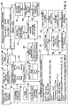
- FIG. 3 illustrates an arrangement in which a DSP unit 25 is used to generate the closed-loop rotor position control signals
- FIG. 3 illustrates an arrangement in which a DSP unit 25 is used to generate the closed-loop rotor position control signals
- analog controller architectures for example, as described in Kipp, R. and Imlach, J., "Control Methodology for Commercial Magnetic Bearing Systems” Proceedings of the PCIM/Power Quality Conference , Irvine, California, September 20-24, 1992, Copyright 1992 by Interfee International, Inc. that could also be used.
- the simplified program loop shown for the main DSP unit 25 is for illustration purposes only and as understood by those of skill in the art would likely be replaced with a much more sophisticated feed-forward linear estimator type algorithm in an actual system implementation.
- the main digital signal processor 25 is provided with a numerical array of actual rotor positions [RPA] and velocities [V] which are obtained from rotor position and velocity transducers located at each magnetic bearing axis. These transducers provide analog rotor position/velocity signals 26 which are appropriately conditioned and converted to numerical values by an analog-to-digital converter 27 and stored in the numerical arrays [RPA] and [V] which reside in a volatile RAM 28 .
- the main digital signal processor also uses a number of externally defined parameters to calculate the closed-loop rotor position control signals. For the illustrative system shown in Figure 3, these parameters are entered via an external computer interface 29, e.g., a portable computer connected to the controller via a serial communication interface, and reside in a non-volatile RAM or other suitable memory device 30 .
- Other parameters residing in the non-volatile RAM 30 are not used by the closed-loop rotor position control section and will be discussed later herein.
- the simple control algorithm shown in the program loop block for the main digital signal processor 25 starts by calculating the rotor position errors [e] by subtracting the actual rotor positions [RPA] from the target rotor positions [RPT] for all bearing axes.
- the rotor position errors [e] are then multiplied by the linear stiffness coefficients [k], and added to the rotor velocities [v], multiplied by the linear damping coefficients [C] to obtain the unfiltered control signals [i].
- the rotor velocity [v] may be estimated from changes in [e] over previous time intervals, since [v] represents the rate of change of [e] with respect to time.
- a state space type algorithm to improve the accuracy of the control signal calculation being performed by the main digital signal processor 25 .
- This is usually done by using one or more previous values of [e] and/or [v] stored in memory to perform a linear regression that can be used to extrapolate what the values of [e] and [v] will be at the time the next set of control signals [i] will be written to an output buffer 31 .
- the time interval at which the [i] values in the output buffer 31 are updated is typically fixed so that the exact time at which the extrapolated estimates of [e] and/or [v] are needed, is known with a great deal of precision.
- This estimation process minimizes error introduced as the actual rotor positions and velocities at each bearing axis change over the time period from when [RPA] and [v] values are obtained to when the [i] values are calculated and written to the output buffer 31 .
- the linear estimator approach to minimizing this error can be further improved by incorporating a simple mathematical model of the machine rotor dynamic response in place of the simple linear extrapolation. This latter method is computationally more insensitive than a linear estimator but is also commonly used and typically results in some compromise between increased computational burden on the digital signal processor and reduced error in the state space estimator.
- the time interval at which the output buffer 31 is updated it is possible to extend the time interval at which the output buffer 31 is updated to a period long enough to perform all PID-type closed-loop rotor position control signal [i] related calculations with time left over to implement notch filtering to attenuate the [i] signal over narrow frequency ranges where excitation of resonances in the machine rotor or support structure must be avoided.
- the control signal generated for each bearing axis may require several notch filters set at various frequencies with various gains, or may not require any notch filtering at all, depending on the resonant response characteristics of the machine rotor and support structure.
- the main digital signal processor 25 program loop incorporates a conditional statement that only executes the digital filter algorithm H ([f m ], [G m ], IQ m ], [i]) if the programmed vibration control mode status indicator [pvcmode] is set to "on" for a given bearing axis, thereby limiting computational demands on the main digital signal processor.
- a secondary digital signal processor 32 is incorporated in the control system to perform open-loop vibration control functions.
- These open-loop functions include an automatic balance mode (abmode) and an adaptive vibration control mode [avcmode] which can be activated via a user interface 33, which toggles the mode status indicators "on” or "off” in a volatile RAM area 34 .
- the secondary digital signal processor 32 uses signals generated by accelerometers 35 or other vibration measurement devices, that are appropriately conditioned and converted to a numerical array of values [a nn ] by analog-to-digital converters 36 and stored in a volatile RAM 37 .
- the open-loop control signals are generated in the form of a numerical array of amplitudes [A n ] and phase angles [ ⁇ n ] which define sinusoidal perturbation signals that are superimposed on the closed-loop control signal [i] being generated by the main digital signal processor. These sinusoidal signals are generated independently for each bearing axis.
- the signal have frequencies equal to the rotational frequency of the machine rotor up to and including the nth harmonic of this frequency or have frequencies which are fractional multiples of the rotational frequency.
- the phase angle array [ ⁇ n ] provides an angular reference for the sinusoidal signals at higher than rotational frequency relative to a known reference on the machine rotor with 360° corresponding to one full cycle at the harmonic frequency, i.e., one complete revolution of the machine rotor.
- the [A n ] and [ ⁇ n ] values are stored in a non-volatile RAM 38 .
- the [A n ] values are then compared by a digital comparator 39 with maximum amplitude values [(A n )max)] which are defined via the external computer interface 29 .
- the [A n ] values reside in the non-volatile RAM 30 , and may be limited if necessary. This precludes perturbation signals of excessive amplitude from being superimposed on the closed-loop rotor position control signals.
- the [A n ] and [ ⁇ n ] values are then sent to a high-frequency digital waveform synthesizer 40 which uses a digital tach/phase reference 41 to produce a separate complex digitized waveform to be superimposed on the closed-loop control signal [i] for each bearing axis.
- the complex digitized waveforms are the sum of all the sinusoidal perturbation signals being applied to each bearing axis and are combined with closed-loop control signals [i] by a high-speed digital adder 42 .
- the output from the adder is sent to a digital-to-analog converter 43, followed by anti-aliasing filters 44 or other signal conditioning.
- the conditioned analog control signals are then sent to power amplifiers 45 followed by bearing control coils 46 . This results in some type of rotor/bearing response 47 that is in turn sensed via the rotor position/velocity signals 26 and the accelerometers 35 .
- the secondary digital signal processor can generate the amplitude [A n ] and phase [ ⁇ n ] values in a manner similar to that commonly used in conventional mechanical rotor balancing techniques.
- a trial weight of known mass is placed at a known radial and angular location in a given balance plane on the machine rotor. Any suitable trial weight mass and location may be selected.
- This addition of a trial weight causes an angular deflection and change in amplitude of the rotational signal of the machine rotor at a given operating speed. These changes are detected by an accelerometer or other vibration detection means on one or more of the machine bearing housings or support structure.
- This system has two unknowns; m o , which is the original rotor imbalance and c, which is sometimes referred to as an influence coefficient.
- m o which is the original rotor imbalance
- c which is sometimes referred to as an influence coefficient.
- an exact correction mass and location can be calculated to correct for the imbalance.
- vibration levels at any of these locations can be adjusted.
- This complete set of influence coefficients, each of which are phasor quantities is generally represented in an n x k matrix where n represents the number of balance planes on the machine rotor where balance weights can be added and k represents the number of locations on the machine structure where the influence of the balance places is determined.
- the values in the influence coefficient matrix are also sensitive to rotational speed since the modal response of the machine rotor and machine structure will be dependent on the frequency of the forcing function, which in mass imbalance calculations is the rotational frequency of the rotor.
- This type of influence coefficient matrix which can be considered to be a type of transfer function, can be generated for a radial magnetic bearing of the type shown in Fig. 1.
- a sinusoidal signal of known amplitude (A 1 ) 1 , and a phase angle ( ⁇ n ) can be generated for a radial magnetic bearing of the type shown in Fig. 1.
- an influence coefficient can be generated for any location of interest on the machine structure.
- This method of generating an influence coefficient matrix may also be extended to axial bearings or even a single axis of a radial bearing. In that case only one sinusoidal perturbation signal is required, instead of two at 90° apart as described above for simultaneous excitation of a vertical and horizontal control axis.
- this method can be used to determine influence coefficients at harmonics of rotational frequency. This is useful in many types of machines such as electric motors or generators where vibration may be caused in the motor/generator frame by electrical excitation at multiples of the fundamental electrical frequency, E, such as the frequencies 2 x E and 6 x E. For two pole motors/generators, these correspond to twice and six times the rotational frequency of the motor. For motors or generators with more than two poles, these electrical excitations will occur at higher harmonics of the rotational frequency. Therefore, by matching the frequency of sinusoidal perturbation signals to the frequencies of these excitations which occur at other than rotational frequency of the rotor, unwanted vibration in the structure of the machine can be reduced, provided at least one bearing has sufficient influence over the location on the structure of interest.
- E fundamental electrical frequency
- the open-loop perturbation signals are added to the closed-loop rotor position control signal using a high speed digital adder 42 .
- the output buffer 31 is only changed by the closed-loop rotor position control loop a few times per revolution of the machine rotor while hundreds or thousands of values from the high-frequency digital waveform synthesizer 40 may be generated during each revolution of the rotor.
- This allows perturbation signals to be superimposed on the closed-loop rotor control signal at harmonics that are many times the rotational frequency.
- Conventional magnetic bearing control systems that incorporate open-loop control features calculate and sum the perturbation signal within the closed-loop control algorithm. This limit the frequency at which open-loop perturbation signals can be injected to rotor rotational frequency, making mass imbalance and other low frequency excitation the only sources of vibration that can be acted on by open-loop signals.
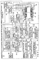
- FIG. 4 A magnetic bearing control system architecture that allows the closed-loop rotor position control and open-loop perturbation signal generation features shown in Fig. 3 to be implemented in a fault-tolerant configuration is shown in Fig. 4.
- a machine rotor 48 is shown passing through a single radial bearing of the type disclosed by Meeks in U.S. Patent No. 5,111,102.
- the more conventional radial baring configuration shown in Fig. 1 may also be used.
- the hybrid bearing configuration shown in Fig. 4 is particularly amenable to fault-tolerant control system configurations, however, because left side and right side control coils 49 and 50 can each be sized to individually control the given bearing axis with relatively small change in the bearing dimensions for a given load rating.
- the bearing is equipped with dual rotor position sensors 52 on each axis, with each sensor having dedicated signal conditioning 53 and analog-to-digital converters 54 and 55 .
- the digitized rotor position signals are then sent to primary and standby DSP based on controllers 56 and 57 .
- the primary and standby controllers 56 and 57 are enabled or disabled by a DSP based supervisor circuit 58 which receives digitized input signals from an analog-to-digital converter 59 .
- This analog-to-digital converter 59 digitizes vibration signals measured by an accelerometer 60 sent via a signal conditioning unit 61 .
- the DSP supervisor is programmed to detect excessive vibration on the bearing or support structure. If a vibration level exceeds a specified safe or desired limit, the active primary DSP based controller 56 is disabled and the inactive standby DSP based controller 57 is enabled.
- vibration level as an independent parameter to detect a malfunctioning controller and implementing logic which prevents more than one controller from being active at a time, e.g., an inverter 64, ensures that a malfunctioning controller will not generate control signals which interfere with the back-up controller.
- Other ways of isolating a malfunctioning or inactive standby controller, such as output isolation, may also be used.
- the DSP based supervisor 58 is also programmed to use the digitized vibration signals from the accelerometer 60 to generate open-loop perturbation signals which are stored in memory areas 62 and 63 . These memory areas are analogous to the non-volatile RAM 38 shown in Fig. 3.
- the DSP based controllers 56 and 57 each incorporate all of the features shown on Fig. 3 required for closed-loop rotor position control.
- each of the DSP based controllers has a digital comparator 39, high-frequency digital waveform synthesizer 40, digital tachometer/phase reference 41, and the high speed digital adder 42 . This allows either DSP based controller to maintain open-loop control functions should the other malfunction.
- a serial communication interface 65 allows the various parameters in the non-volatile RAM 30 shown in Fig. 3 to be loaded into each DSP based controller 56 and 57 .
- Two pulse-width modulated (PWM) amplifiers 66, 67 can receive control signals from either DSP based controller 56 or 57 .
- the PWM Power Amplifier 66 drives the right side control coils 50 while the left side coils 49 driven by the PWM Power Amplifier 67 .
- Each amplifier drives through fuses or other passive overcurrent protection devices 68 .
- Redundancy in the power supply section is provided by incorporating two independent DC power supplies 69 and 70 driving through diodes so that if one unit fails, DC power to the circuit is maintained.
- a similar configuration is used for two logic level, e.g., 5VDC power supplies 71 and 72 .
- the main power supplies 69 and 70 are each connected to independent buses, BUS 1 and BUS 2, to provide further redundancy.
- the DSP based controllers 56 and 57, DSP based supervisor 58, PWM power amplifiers 66 and 67, DC power supplies 69 and 70, and logic level power supplies 71 and 72 each incorporate fault indication outputs F which are fed into a fault detection and indication logic/display 73, which is simply a set of lights or other type of enunciator that indicates when a particular portion of the system has suffered a fault.
- FIG. 4 The arrangement shown in Fig. 4 would typically be used to operate a large number of bearings, each having the features shown in the boundary labeled "common to each axis of the 5 axis controller ( 74 )". As recognized by those skilled in the art the arrangement can be used to operate different bearing configurations as well.
- a rotor system such as that shown in Fig. 2, typically has 5 axes, consisting of two radial bearings, each having a vertical and horizontal control axis, and a thrust bearing which controls the axial position of the rotor. Rotor systems and magnetic bearing system controllers may also be designed which have fewer or a greater number of axes.
- Each 5-axis controller contains the features shown in Fig.
- the 5-axis controller may be installed in an enclosure along with four power supplies 69, 70 , 71 and 72 and a fault indication unit 73 shown in Fig. 4 within the boundaries labeled "common to each controller enclosure ( 76 ).”
Landscapes
- Engineering & Computer Science (AREA)
- General Engineering & Computer Science (AREA)
- Mechanical Engineering (AREA)
- Signal Processing (AREA)
- Physics & Mathematics (AREA)
- Electromagnetism (AREA)
- Magnetic Bearings And Hydrostatic Bearings (AREA)
Applications Claiming Priority (2)
| Application Number | Priority Date | Filing Date | Title |
|---|---|---|---|
| US862816 | 1997-05-30 | ||
| US08/862,816 US5925957A (en) | 1997-05-30 | 1997-05-30 | Fault-tolerant magnetic bearing control system architecture |
Publications (2)
| Publication Number | Publication Date |
|---|---|
| EP0881404A2 true EP0881404A2 (fr) | 1998-12-02 |
| EP0881404A3 EP0881404A3 (fr) | 2000-01-19 |
Family
ID=25339445
Family Applications (1)
| Application Number | Title | Priority Date | Filing Date |
|---|---|---|---|
| EP98201792A Withdrawn EP0881404A3 (fr) | 1997-05-30 | 1998-05-29 | Agencement de palier |
Country Status (4)
| Country | Link |
|---|---|
| US (2) | US5925957A (fr) |
| EP (1) | EP0881404A3 (fr) |
| JP (1) | JP3333739B2 (fr) |
| DE (1) | DE881404T1 (fr) |
Cited By (6)
| Publication number | Priority date | Publication date | Assignee | Title |
|---|---|---|---|---|
| EP1076187A3 (fr) * | 1999-08-12 | 2002-07-31 | Seiko Seiki Kabushiki Kaisha | Dispositif de palier magnétique |
| CN112901658A (zh) * | 2021-03-22 | 2021-06-04 | 华中科技大学 | 一种用于磁悬浮轴承的开关断路故障容错控制系统 |
| CN113107975A (zh) * | 2021-04-07 | 2021-07-13 | 华中科技大学 | 用于磁轴承的绕组控制器断路故障定位、容错方法和系统 |
| CN114263677A (zh) * | 2021-12-27 | 2022-04-01 | 华中科技大学 | 一种应用于磁悬浮轴承的五桥臂容错控制方法及系统 |
| CN115076233A (zh) * | 2022-07-05 | 2022-09-20 | 广东美的暖通设备有限公司 | 磁悬浮电机及其控制方法和装置、可读存储介质 |
| CN119935044A (zh) * | 2025-04-08 | 2025-05-06 | 山东华东风机有限公司 | 一种高可靠性磁悬浮轴承位置检测方法及实现装置 |
Families Citing this family (26)
| Publication number | Priority date | Publication date | Assignee | Title |
|---|---|---|---|---|
| US6107770A (en) * | 1998-01-27 | 2000-08-22 | Lockheed Martin Corporation | Control system for counter-oscillating masses |
| WO1999040334A1 (fr) * | 1998-02-03 | 1999-08-12 | Sulzer Electronics Ag | Procede et dispositif d'amorçage de systemes a enroulement pour force portante et a enroulement pour force d'entrainement dans des machines electriques a palier magnetique, et entrainement electrique |
| US6267876B1 (en) * | 1998-07-31 | 2001-07-31 | Trinity Flywheel Power | Control of magnetic bearing-supported rotors |
| DE59915016D1 (de) * | 1998-08-24 | 2009-06-18 | Levitronix Llc | Verfahren zum Bestimmen der radialen Position eines permanentmagnetischen Rotors und elektromagnetischer Drehantrieb |
| JP3130890B2 (ja) * | 1999-02-25 | 2001-01-31 | セイコー精機株式会社 | 磁気軸受装置及び磁気軸受制御装置 |
| EP1063753B1 (fr) * | 1999-06-22 | 2009-07-22 | Levitronix LLC | Entraînement électrique rotatif comprenant un rotor suspendu magnétiquement |
| US6590366B1 (en) * | 2000-11-02 | 2003-07-08 | General Dyanmics Advanced Technology Systems, Inc. | Control system for electromechanical arrangements having open-loop instability |
| US6734650B2 (en) * | 2002-01-30 | 2004-05-11 | Honeywell International, Inc. | System and method for controlling an active magnetic bearing using continuous variable compensation |
| KR100584548B1 (ko) * | 2002-06-29 | 2006-05-30 | 삼성전자주식회사 | 동작 환경에 빠르게 적응 가능한 모터 제어 시스템 및 방법 |
| US7312595B2 (en) * | 2002-07-09 | 2007-12-25 | Denso Corporation | Motor control apparatus |
| US20050174087A1 (en) * | 2004-02-10 | 2005-08-11 | Koyo Seiko Co., Ltd. | Control magnetic bearing device |
| US6909948B2 (en) * | 2003-04-30 | 2005-06-21 | General Electric Company | Accelerometer configuration |
| US7429811B2 (en) * | 2004-06-01 | 2008-09-30 | The Texas A&M University System | Fault tolerant homopolar magnetic bearings |
| BRPI0511385A (pt) * | 2004-06-15 | 2007-12-04 | Aly El-Shafei | métodos para controlar a instabilidade em rolamentos de pelìcula de fluido |
| EP1615141B1 (fr) * | 2004-07-01 | 2018-03-07 | Harman Becker Automotive Systems GmbH | Architecture d'ordinateur pour un système multimedia mobile utilisé dans un véhicule |
| US20060055259A1 (en) * | 2004-09-14 | 2006-03-16 | Casey Hanlon | Fault-tolerant magnetic bearing position sensing and control system |
| JP4067541B2 (ja) * | 2005-07-04 | 2008-03-26 | トヨタ自動車株式会社 | 車両制御装置および車両制振方法 |
| US8690749B1 (en) | 2009-11-02 | 2014-04-08 | Anthony Nunez | Wireless compressible heart pump |
| JP5279890B2 (ja) * | 2011-12-29 | 2013-09-04 | 株式会社大阪真空機器製作所 | ラジアル方向制御器及び、それが適用された磁気軸受装置 |
| HK1200898A1 (en) * | 2012-04-04 | 2015-08-14 | Carrier Corporation | Multiple-axis magnetic bearing and control of the magnetic bearing with a topology including active switches |
| JP5997597B2 (ja) * | 2012-12-10 | 2016-09-28 | 株式会社荏原製作所 | 磁気軸受装置、磁気軸受装置に起因する振動の低減方法 |
| EP3334962B1 (fr) | 2015-08-10 | 2019-09-18 | Exxonmobil Upstream Research Company | Dispositif et procédé pour joint à gaz sec à commande magnétique |
| US10132412B2 (en) | 2016-08-05 | 2018-11-20 | Exxonmobil Upstream Research Company | Device and method for controlling rotating equipment seal without buffer support equipment |
| US10386808B2 (en) * | 2017-02-24 | 2019-08-20 | Danfoss Power Electronics A/S | System parameter identificatino method based on rate-limited relay with hysteresis and sinusoidal injection |
| EP3467338A1 (fr) * | 2017-10-09 | 2019-04-10 | Mecos AG | Équilibrage d'un rotor dans un dispositif de palier magnétique |
| CN113719539B (zh) * | 2021-08-25 | 2023-02-03 | 中国人民解放军海军工程大学 | 磁悬浮轴承位移传感器容错控制系统及控制方法 |
Citations (1)
| Publication number | Priority date | Publication date | Assignee | Title |
|---|---|---|---|---|
| US5111102A (en) | 1989-05-25 | 1992-05-05 | Meeks Crawford R | Magnetic bearing structure |
Family Cites Families (23)
| Publication number | Priority date | Publication date | Assignee | Title |
|---|---|---|---|---|
| US4090745A (en) * | 1974-01-14 | 1978-05-23 | Sperry Rand Corporation | Magnetic suspension with magnetic stiffness augmentation |
| DE3120691A1 (de) * | 1981-05-23 | 1982-12-16 | Teldix Gmbh, 6900 Heidelberg | Magnetlager |
| JPS63285321A (ja) * | 1987-05-18 | 1988-11-22 | Ebara Corp | 不釣り合い振動及び同期妨害振動の防止制御方式 |
| JP2516382B2 (ja) * | 1987-11-06 | 1996-07-24 | セイコー精機株式会社 | 磁気軸受を主軸にもつ加工装置 |
| FR2630354B1 (fr) * | 1988-04-20 | 1990-08-31 | Mecanique Magnetique Sa | Dispositif vibrateur actif a suspension magnetique asservie selon trois axes |
| JP3068834B2 (ja) * | 1988-06-06 | 2000-07-24 | テルデイクス ゲゼルシヤフト ミツト ベシユレンクテル ハフツング | 大きい半径を有する回転子をラジアル及びアキシヤル軸受する軸受 |
| US5347190A (en) * | 1988-09-09 | 1994-09-13 | University Of Virginia Patent Foundation | Magnetic bearing systems |
| US4912387A (en) * | 1988-12-27 | 1990-03-27 | Westinghouse Electric Corp. | Adaptive noise cancelling for magnetic bearing auto-balancing |
| JP2824459B2 (ja) * | 1989-04-28 | 1998-11-11 | 株式会社フェローテック | 磁気軸受装置 |
| US5216308A (en) * | 1989-05-25 | 1993-06-01 | Avcon-Advanced Controls Technology, Inc. | Magnetic bearing structure providing radial, axial and moment load bearing support for a rotatable shaft |
| US5013987A (en) * | 1989-07-18 | 1991-05-07 | Seiko Instruments Inc. | Control system for magnetic bearing |
| US5003211A (en) * | 1989-09-11 | 1991-03-26 | The United States Of America As Represented By The Administrator Of The National Aeronautics And Space Administration | Permanent magnet flux-biased magnetic actuator with flux feedback |
| US4999534A (en) * | 1990-01-19 | 1991-03-12 | Contraves Goerz Corporation | Active vibration reduction in apparatus with cross-coupling between control axes |
| JP2834832B2 (ja) * | 1990-03-15 | 1998-12-14 | 松下電工株式会社 | 姿勢制御装置 |
| JPH0720359B2 (ja) * | 1990-03-16 | 1995-03-06 | 株式会社荏原製作所 | 回転体のアンバランス修正装置 |
| US5202824A (en) * | 1990-06-21 | 1993-04-13 | Mechanical Technology Incorporated | Rotating force generator for magnetic bearings |
| US5157296A (en) * | 1990-12-20 | 1992-10-20 | Massachusetts Institute Of Technology | Bearing for use in high resolution precision control device |
| US5084643A (en) * | 1991-01-16 | 1992-01-28 | Mechanical Technology Incorporated | Virtual rotor balancing in magnetic bearings |
| US5313399A (en) * | 1992-01-21 | 1994-05-17 | The Charles Stark Draper Laboratories, Inc. | Adaptive synchronous vibration suppression apparatus |
| US5469006A (en) * | 1992-09-25 | 1995-11-21 | Magnetic Bearing Technologies, Inc. | Lorentz force magnetic bearing utilizing closed conductive loops and selectively controlled electromagnets |
| US5300843A (en) * | 1992-11-02 | 1994-04-05 | General Electric Company | Fault tolerant active magnetic bearing |
| US5300841A (en) * | 1992-11-02 | 1994-04-05 | General Electric Company | Inductive air gap estimation method for active magnetic bearings |
| US5666013A (en) * | 1992-12-07 | 1997-09-09 | Seiko Seiki Kabushiki Kaisha | Magnetic bearing |
-
1997
- 1997-05-30 US US08/862,816 patent/US5925957A/en not_active Expired - Fee Related
-
1998
- 1998-05-28 JP JP14724798A patent/JP3333739B2/ja not_active Expired - Fee Related
- 1998-05-29 EP EP98201792A patent/EP0881404A3/fr not_active Withdrawn
- 1998-05-29 DE DE0881404T patent/DE881404T1/de active Pending
- 1998-06-03 US US09/089,536 patent/US6005315A/en not_active Expired - Fee Related
Patent Citations (1)
| Publication number | Priority date | Publication date | Assignee | Title |
|---|---|---|---|---|
| US5111102A (en) | 1989-05-25 | 1992-05-05 | Meeks Crawford R | Magnetic bearing structure |
Non-Patent Citations (4)
Cited By (9)
| Publication number | Priority date | Publication date | Assignee | Title |
|---|---|---|---|---|
| EP1076187A3 (fr) * | 1999-08-12 | 2002-07-31 | Seiko Seiki Kabushiki Kaisha | Dispositif de palier magnétique |
| CN112901658A (zh) * | 2021-03-22 | 2021-06-04 | 华中科技大学 | 一种用于磁悬浮轴承的开关断路故障容错控制系统 |
| CN112901658B (zh) * | 2021-03-22 | 2021-12-03 | 华中科技大学 | 一种用于磁悬浮轴承的开关断路故障容错控制系统 |
| CN113107975A (zh) * | 2021-04-07 | 2021-07-13 | 华中科技大学 | 用于磁轴承的绕组控制器断路故障定位、容错方法和系统 |
| CN113107975B (zh) * | 2021-04-07 | 2022-04-26 | 华中科技大学 | 用于磁轴承的绕组控制器断路故障定位、容错方法和系统 |
| CN114263677A (zh) * | 2021-12-27 | 2022-04-01 | 华中科技大学 | 一种应用于磁悬浮轴承的五桥臂容错控制方法及系统 |
| CN115076233A (zh) * | 2022-07-05 | 2022-09-20 | 广东美的暖通设备有限公司 | 磁悬浮电机及其控制方法和装置、可读存储介质 |
| CN115076233B (zh) * | 2022-07-05 | 2024-03-01 | 广东美的暖通设备有限公司 | 磁悬浮电机及其控制方法和装置、可读存储介质 |
| CN119935044A (zh) * | 2025-04-08 | 2025-05-06 | 山东华东风机有限公司 | 一种高可靠性磁悬浮轴承位置检测方法及实现装置 |
Also Published As
| Publication number | Publication date |
|---|---|
| US5925957A (en) | 1999-07-20 |
| EP0881404A3 (fr) | 2000-01-19 |
| US6005315A (en) | 1999-12-21 |
| DE881404T1 (de) | 1999-05-06 |
| JPH10331851A (ja) | 1998-12-15 |
| JP3333739B2 (ja) | 2002-10-15 |
Similar Documents
| Publication | Publication Date | Title |
|---|---|---|
| US5925957A (en) | Fault-tolerant magnetic bearing control system architecture | |
| US5202824A (en) | Rotating force generator for magnetic bearings | |
| US4999534A (en) | Active vibration reduction in apparatus with cross-coupling between control axes | |
| EP1771667B1 (fr) | Procede et dispositif de commande de palier magnetique | |
| US5313399A (en) | Adaptive synchronous vibration suppression apparatus | |
| US6763285B2 (en) | Adaptive compensation of sensor run-out and mass unbalance in magnetic bearing systems without changing rotor speed | |
| US5084643A (en) | Virtual rotor balancing in magnetic bearings | |
| Cui et al. | Harmonic current suppression of an AMB rotor system at variable rotation speed based on multiple phase-shift notch filters | |
| EP0446816B1 (fr) | Appareil de correction de déséquilibrage d'un rotor | |
| KR20020030033A (ko) | 자기 베어링 장치 | |
| Fang et al. | Adaptive complete suppression of imbalance vibration in AMB systems using gain phase modifier | |
| JPH02213907A (ja) | 磁気軸受を自動平衡させるためのサーボ制御ループ装置 | |
| US7370524B2 (en) | Adaptive vibration control using synchronous demodulation with machine tool controller motor commutation | |
| Betschon et al. | Reducing magnetic bearing currents via gain scheduled adaptive control | |
| Sun et al. | Disturbance force self-sensing and suppression method for AMB-rotor system based on disturbance observer | |
| Dyer et al. | Adaptive influence coefficient control of single-plane active balancing systems for rotating machinery | |
| JP2025011358A (ja) | 磁気軸受の制御装置および制御方法 | |
| CN116047907A (zh) | 一种基于复数lms算法的磁轴承同频振动力抑制方法 | |
| Ye et al. | Vibration suppression for active magnetic bearings using adaptive filter with iterative search algorithm | |
| EP2740954B1 (fr) | Appareil à palier magnétique et procédé de réduction des vibrations causées par l'appareil à palier magnétique | |
| KR20140028130A (ko) | 래디얼 방향 제어기 및 그것이 적용된 자기 축받이 장치 | |
| Kurnyta-Mazurek et al. | Control system with a non-parametric predictive algorithm for a high-speed rotating machine with magnetic bearings | |
| JP2002188630A (ja) | 磁気軸受の制御装置およびこれを用いた磁気軸受スピンドル装置 | |
| Abulrub et al. | Adaptive control of active magnetic bearings to prevent rotor-bearing contact | |
| JPH09280250A (ja) | バランサ兼オーバスピン装置 |
Legal Events
| Date | Code | Title | Description |
|---|---|---|---|
| PUAI | Public reference made under article 153(3) epc to a published international application that has entered the european phase |
Free format text: ORIGINAL CODE: 0009012 |
|
| AK | Designated contracting states |
Kind code of ref document: A2 Designated state(s): DE FR GB IT |
|
| AX | Request for extension of the european patent |
Free format text: AL;LT;LV;MK;RO;SI |
|
| ITCL | It: translation for ep claims filed |
Representative=s name: INGG. GUZZI RAVIZZA |
|
| EL | Fr: translation of claims filed | ||
| 17P | Request for examination filed |
Effective date: 19990127 |
|
| DET | De: translation of patent claims | ||
| PUAL | Search report despatched |
Free format text: ORIGINAL CODE: 0009013 |
|
| AK | Designated contracting states |
Kind code of ref document: A3 Designated state(s): AT BE CH CY DE DK ES FI FR GB GR IE IT LI LU MC NL PT SE |
|
| AX | Request for extension of the european patent |
Free format text: AL;LT;LV;MK;RO;SI |
|
| AKX | Designation fees paid |
Free format text: DE FR GB IT |
|
| GRAP | Despatch of communication of intention to grant a patent |
Free format text: ORIGINAL CODE: EPIDOSNIGR1 |
|
| RTI1 | Title (correction) |
Free format text: MAGNETIC BEARING WITH CONTROL ARRANGEMENT |
|
| STAA | Information on the status of an ep patent application or granted ep patent |
Free format text: STATUS: THE APPLICATION IS DEEMED TO BE WITHDRAWN |
|
| 18D | Application deemed to be withdrawn |
Effective date: 20041130 |
|
| R18D | Application deemed to be withdrawn (corrected) |
Effective date: 20041201 |