EP0881791A2 - System zur optischen Übertragung von Informationen - Google Patents
System zur optischen Übertragung von Informationen Download PDFInfo
- Publication number
- EP0881791A2 EP0881791A2 EP98440087A EP98440087A EP0881791A2 EP 0881791 A2 EP0881791 A2 EP 0881791A2 EP 98440087 A EP98440087 A EP 98440087A EP 98440087 A EP98440087 A EP 98440087A EP 0881791 A2 EP0881791 A2 EP 0881791A2
- Authority
- EP
- European Patent Office
- Prior art keywords
- optical
- information
- signals
- network termination
- sys
- Prior art date
- Legal status (The legal status is an assumption and is not a legal conclusion. Google has not performed a legal analysis and makes no representation as to the accuracy of the status listed.)
- Granted
Links
Images



Classifications
-
- H—ELECTRICITY
- H04—ELECTRIC COMMUNICATION TECHNIQUE
- H04B—TRANSMISSION
- H04B10/00—Transmission systems employing electromagnetic waves other than radio-waves, e.g. infrared, visible or ultraviolet light, or employing corpuscular radiation, e.g. quantum communication
- H04B10/27—Arrangements for networking
- H04B10/272—Star-type networks or tree-type networks
Definitions
- the invention relates to a system for the optical transmission of Information according to the preamble of claim 1.
- WO 95/05041 describes a system for the optical transmission of Information from a sub-center via several optical Transmission lines to several optical network termination units known.
- the sub-center is made up of a passive optical distribution network optical transmission lines and an optical splitter with the optical network termination units connected.
- the Subcarrier signals are, for example, television signals for all optical Network termination units are intended and telephone signals, each only are intended for an optical network termination unit.
- telephone signals are only one reserved small frequency range.
- these relatively small frequency range is not sufficient to cover a sufficient range large number of channels available for the multitude of endpoints put.
- the invention is particularly characterized in that the system several nodes for the optical transmission of further information and includes several optical couplers, and that the others Information from each node via a coupler into one Transmission line can be fed, which only with a part of the several optical network termination units is connected.
- the first exemplary embodiment will now be described with the aid of FIG. 1 explained.
- the SYS system includes one Sub-center HUB with a first optical transmission line an optical network termination unit ONU1 and a second optical Transmission line with an optical network termination unit ONU2 connected is. From the sub-center, the first information about optical network termination unit ONU1 and a second information for optical network termination unit ONU2 transmitted.
- the first and the second Information can be identical, e.g. in the case of a distribution service, such as distributing television signals, or differently, e.g. in case of a Data transmission.
- the system SYS also contains two nodes K1, K2 for optical Transfer of further information.
- the further information of the Node K1 e.g. Telephone signals or data signals are exclusive intended for the optical network termination unit ONU1 and not for the optical network termination unit ONU2. For this reason, the further information of the node K1 about another Transmission line and an optical coupler C1, which is in the first Transmission line is looped in over part of the first Transmission line together with the information from the sub-center Transfer HUB to the optical network termination unit ONU1.
- the further information of the node K2 e.g. Telephone signals or Data signals are only for the optical network termination unit ONU2 determined and not for the optical network termination unit ONU1. Out for this reason, the further information of the node K2 about a further transmission line and an optical coupler C2, which in the second transmission line is looped in, over part of the second Transmission line together with the information from the sub-center Transfer HUB to the optical network termination unit ONU2.
- the further information of the nodes K1 and K2 are thus open optical path with the information of the sub-center HUB summarized and the optical network termination units ONU 1 and ONU2 supplied, for example, each with a group of terminals are connected.
- groups of terminals can both Distribution information as well as special, only for a particular one Group of endpoints certain information inexpensively and under optimal utilization of the existing transmission capacity will.
- the second exemplary embodiment will now be continued with the aid of FIG. 2 explained.
- 2 shows an inventive system SYS for optical Transmission of information.
- the SYS system includes one Sub-center HUB, which uses a passive optical transmission network optical transmission lines and three optical splitters with four optical network termination units ONU1, ONU2, ONU3, ONU4 connected is.
- the optical network termination unit ONU2 has two different ones Paths connected to the HUB sub-center. Through this redundancy the optical network termination unit ONU2 from the sub-center HUB sent information twice and can choose from them.
- the introduction of two different ways serves among other things the other Availability of a connection in the event of a connection failure.
- the system SYS also contains three nodes K1, K2, K3 for optical Transmission of further information, in particular information, only for one or two of the four optical network termination units ONU1, ONU2, ONU3, ONU4 are determined.
- the further information of the node K1 is for the optical Network termination units ONU1 and ONU2 determined. You will have one additional optical transmission line and an optical coupler C1, which is looped into the optical transmission line, which over a optical splitter with the optical network termination units ONU1 and ONU2 is connected to the optical network termination units ONU1 and Transfer ONU2.
- the further information of the node K2 is for the optical Network termination units ONU2 and ONU3 determined. You will have one additional optical transmission line and an optical coupler C2 fed into the transmission line using an optical splitter the optical network termination units ONU2 and ONU3 is connected. Out in this way the further information of the node K2 both arrive to the optical network termination unit ONU2 as well as to the optical Network termination unit ONU3.
- the further information of node K1 and the further information of the node K2, which is used for the optical Network termination unit ONU2 are intended to be the same as what Redundancy creates and the further availability of a connection, in the event a failure of a connection means or be different what to leads to an increased transmission capacity, for example double Transmission capacity compared to the optical Network termination units ONU1 and ONU2.
- the distribution of the available Transmission channels to the optical network termination units ONU1, ONU2 and ONU3 can also be done dynamically, so that one at the Traffic distribution adjusted during operation can.
- the transmission capacity of the node K1 10 Mbit / s e.g.
- nodes K1 e.g. 5 Mbit / s for the optical network termination unit ONU1 and 5 Mbit / s for the optical network termination unit ONU2 can be used as well as Node K2 e.g. 5 Mbit / s for the optical network termination unit ONU3 and 5 Mbit / s can be used for the optical network termination unit ONU2 that a total of 10 Mbit / s for the optical network termination unit ONU2 can be used.
- node K3 The further information of node K3 is only for the optical network termination device ONU4 determined. You will have one additional optical transmission line and an optical coupler C3 fed into the transmission line that directly with the optical Network termination devices ONU4 is connected.
- FIG. 3 shows a system SYS according to the invention for optical transmission of information.
- the system is SYS for example, a hybrid fiber optic coaxial cable access system that for example the transmission of analog and / or digital television and video signals from a sub-center HUB to several end points END and the transmission of interactive polling signals from several End points END to the sub-center HUB. From the end points is END an example is shown.
- the SYS system is also used for Transmission of data and / or telephone signals from several Node K1, ..., Km to groups of end points END and the transmission of telephone and / or data signals from groups of terminals END to nodes K1, ..., km.
- the from the sub-center, e.g. a cable television head-end, too Transmitting signals are electrical / optical in the sub-center HUB implemented and via a passive optical distribution network of optical Transmission lines, e.g. Fiber optic cables and optical splitters too several optical network termination units ONU1n, one of which is shown is transferred. There is one in each optical network termination unit ONU1n optical / electrical implementation of the signals received instead then electrically via coaxial cable to a group of end points END are transmitted.
- the video signals are from, for example Participants selected interactive films, educational programs or the like.
- the end station END has its own house network to which the subscriber has access has and to which he can connect numerous devices.
- the end devices are, for example, a computer PC connected via a modem TV connected to a set-top box STB, a telephone TEL or a fax machine FAX.
- the nodes K1, ..., Km are each in two ways with the corresponding ones optical network termination units ONU1n connected.
- the node is K1 for example via an additional optical transmission line and one optical coupler C1, which in the first transmission line after the 1: m Splitter is inserted, with the n optical network termination units ONU1n connected via a 1: n splitter to this first optical Transmission line are connected.
- To each optical network termination unit ONU1n is connected to a group of end points END. Every group contains for example 20 end points END, so that with the node K1 200 end points are connected.
- Node K1 e.g.
- Telephone or Videophone connections to these terminals END The transfer of information from the end points END to the node K1 takes place via a additional passive optical distribution network, for example with a optical n: 1 combiner, as shown in Fig. 3, or via n separate Transmission lines, each an optical network termination unit Connect ONU1n directly to node K1.
- the nodes K2 to Km are comparable to the node K1 with the associated optical network termination units and the groups connected by end points END. Information is transferred corresponding.
- the nodes K1, ..., Km are each via an optical or an electrical Transmission line connected to the sub-center HUB.
- the nodes K1, ..., Km include means for dividing those connected to them optical network termination units ONU1n received information and Means for forwarding part of the optical Network termination units ONU received information about the sub-center HUB.
- the information contains the optical Network termination units ONU1n interactive polling signals and Telephone signals.
- the polling signals and Telephone signal separated from each other, e.g. by means of electrical Bandpasses after an optical / electrical implementation with a Photodiode.
- the polling signals become Sub-center forwarded, e.g. by means of an electrical / optical converter.
- the nodes K1, ..., Km are e.g. with a telephone network NET, e.g. one integrated digital network, the so-called ISDN.
- a telephone network NET e.g. one integrated digital network
- the so-called ISDN the so-called ISDN.
- About everyone Node K1, ..., Km become at least telephone signals from the ISDN a group of terminals END and telephone signals of at least a group of terminals END in ISDN.
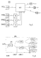
- FIG. 4 shows a section of the optical network termination unit ONU1n from Fig. 3.
- the detail shows an intermediate link, which during transmission of information is used from the end points to the nodes.
- the link serves to suppress interference and contains two Switches S1, S2, two bandpass filters BP1, BP2, a control unit CTRL and an electrical / optical converter E / O.
- the two switches S1, S2 serve to at least part of the Frequency range of the information transfer to the respective Node K1, ..., Km is used to activate or block the transmission becomes. In the event that none in this part of the frequency range The frequency range is blocked.
- the two bandpass filters BP1, BP2, alternatively also crossovers or Bandstops serve to divide the frequency range of the Information transfer to the respective node K1, ..., Km is used.
- the Bandpass filter BP1 blocks e.g. all frequencies except for those interactive signals.
- the bandpass filter BP2 blocks e.g. all frequencies, except those for the telephone signals.
- the control unit CTRL is used to detect the signal levels in the divided frequency ranges and for controlling the two switches S1, S2.
- the control unit CTRL contains, for example Amplitude detector, which the amplitudes of the interactive call signals and of the telephone signals detected and each with an upper and a compares lower threshold.
- the upper threshold is a maximum value that must not be exceeded, otherwise there will be disruptions on the Transmission line is coming.
- the lower threshold is a minimum Threshold that must not be undercut because the signal due to the Attenuation on the transmission line in the node is no longer detectable is.
- the two switches S1 and S2 are activated in such a way that for the Case that the corresponding signal level is below a predetermined minimum threshold or above a predetermined upper threshold the corresponding frequency range is blocked.
- information about optical Couplers summarized and together via an optical Transmission line The one from the sub-center HUB transmitted information and from the multiple nodes K1, ..., Km transmitted further information can be different Wavelengths are transmitted. This has the advantage that the Summary of information the possibility of occurrence of Interference is reduced. It also stands for both Sub-center HUB as well as for each individual node K1, ..., Km larger frequency range available for information transmission, so that a higher number of transmission channels is possible.
- 5 shows a system SYS according to the invention for the optical transmission of information.
- the SYS system contains four electrical / optical converters E / O1, E / O2, E / O3, E / O4 for converting and transmitting four different pieces of information.
- the electrical / optical converter E / O1 is used to convert electrical television signals CATV into optical signals with the wavelength ⁇ 1 and to transmit them via an optical transmission line to a broadband signal distribution device VER.
- the television signals are split into several optical signals, in order to then transmit them via several optical transmission lines to a number of optical / electrical converters O / E, which convert the optical signals back into the electrical television signals, so that they can be used, for example, at several terminals can be fed via coaxial cable.
- the SYS system is thus, among other things, a distribution system for CATV cable television signals.
- the electrical / optical converter E / O2 is used to convert and transmit near-video-on-demand signals NVOD. These are video signals that are repeatedly broadcast at predetermined time intervals and for which the participant has to pay a fee. To avoid optical interference, they can be transmitted at the wavelength ⁇ 2 ⁇ ⁇ 1 .
- the optical near-video-on-demand signals NVOD are fed to an optical attenuator T0 via an optical transmission line. This optical attenuator T0 is used to adjust the signal amplitude of the optical near-video-on-demand signals NVOD so that the already existing television signals CATV are influenced as little as possible.
- the optical output signal of the attenuator T0 is fed to the optical signal distribution device VER via a further optical transmission line.
- the optical near-video-on-demand signals NVOD are linked to the optical television signals CATV in order to transmit them together to the plurality of terminals via the same optical transmission lines.
- the optical signal distribution device VER is operated, for example, in wavelength division multiplexing.
- the electrical / optical converter E / O3 is used for the conversion and transmission of cablephone signals CABLE1.
- Optical cablephone signals are telephone signals that are transmitted via optical transmission lines.
- the optical cablephone signals CABLE1 are supplied, for example at the wavelength ⁇ 3 ⁇ ⁇ 2 ⁇ ⁇ 1, via an optical transmission line to an optical attenuator T1, in which the signal levels are adjusted, comparable to the optical attenuator T0.
- the optical cablephone signals CABLE1 are then fed to the optical signal distribution device VER via a further optical transmission line.
- the cablephone signals CABLE1 should only be fed to some of the end stations.
- the optical signal distribution device VER It is therefore provided in the optical signal distribution device VER to link the cablephone signals CABLE1 to the optical television signals CATV and the optical near-video-on-demand signals such that they are only supplied to a part of the optical transmission lines at the output of the optical signal distribution device VER, so that they only reach part of the optical / electrical converters O / E. This will be discussed in more detail below.
- Fig. 5 only the forward channel for the optical cablephone signals is shown.
- An implementation for the return channel can be seen, for example, in FIG. 3.
- the electrical / optical converter E / O4 is used for the conversion and transmission of cablephone signals CABLE2.
- the optical cablephone signals CABLE2 are transmitted, for example, at the wavelength ⁇ 3 ⁇ ⁇ 2 ⁇ ⁇ 1 . They are routed to the part of the terminals that do not already have access to a telephone network through the cablephone signals CABLE1.
- the optical cablephone signals CABLE2 are transmitted via an optical transmission line, an optical attenuator T2, the function of which is also to adjust the signal levels, as explained above for the optical attenuator T0, and a further optical transmission line to the optical signal distribution device VER.
- the optical cablephone signals CABLE2 are linked to the optical television signals CATV and the optical near-video-on-demand signals NVOD in such a way that on the one hand they are not superimposed on the optical cablephone signals CABLE1 and on the other hand all the optical / electrical converters O / E that cannot be reached by the optical cablephone signals CABLE1.
- the optical signal distribution device VER can also be other optical signals are supplied, which are not discussed in detail.
- the near-video-on-demand signals NVOD and the Cablephone signals CABLE1 and CABLE2 can also do other Information is transmitted, for example video on demand Signals, and thus other services are made available.
- At Video-on-demand signals each terminal must have its own broadband Transmission channel can be made available, whatever the requirement the transmission capacity increased.
- the use of optical Attenuators T0, T1, T2 is optional and depends on the optical Output power of the electrical / optical converter as well as from the Distribution depth of the respective services. With system SYS from Fig. 5 especially unidirectional distribution signals (CATV) with bidirectional Signals (CABLE1, CABLE2) linked.
- CATV unidirectional distribution signals
- CABLE1, CABLE2 bidirectional Signals
- the optical signal distribution device VER contains seven broadband optical splitters Sp1, SP2, SP3, SP4, SP5, Sp6, SP7. Each of the seven optical splitters SP1 to SP7 has two inputs and two outputs. It is used to link two different signals and to feed the linked signals to both outputs at the same time.
- optical splitters which are also referred to as optical couplers, in particular as 2x2 couplers, are described, for example, in Electronic Letters, August 15, 1985, vol. 21, no. 17, pages 742-743.
- the optical splitter SP1 has the optical television signals CATV at one input and the optical near-video-on-demand signals NVOD at the other input.
- the electrical television signals are in the frequency range 100-400 MHz and the electrical near-video-on-demand signals are in the frequency range 410-800MHz.
- optical NVOD Splitter SP1 The interconnected optical television signals CATV and the Optical near-video-on-demand signals are used in optical NVOD Splitter SP1 divided into two signals and the two splitter outputs fed.
- the two splitter output signals have the same Signal level and include both the optical television signals CATV and also the optical near-video-on-demand signals NVOD.
- the optical signals become an input of the optical splitter SP2 an output of the optical splitter SP1.
- An entrance to the optical splitter SP3 are the optical signals of the other output of the optical splitter SP1 supplied.
- the other input of the optical The optical cablephone signals CABLE1 are fed to splitters SP2.
- the other input of the optical splitter SP3 are the optical Cablephone signals CABLE2 supplied.
- optical splitter SP2 those that are already linked to one another are thus optical television signals CATV and optical near video on demand NVOD signals additionally with the optical cablephone signals CABLE1 connected.
- Each output of the optical splitter SP2 thus serves Transmission of signals, including an optical link CATV television signals, near-video-on-demand optical signals NVOD and optical cablephone signals CABLE1.
- optical splitter SP3 those that are already linked to one another are optical television signals CATV and optical near video on demand NVOD signals additionally with the optical cablephone signals CABLE2 connected.
- Each output of the optical splitter SP3 is used for Transmission of signals, including an optical link CATV television signals, near-video-on-demand optical signals NVOD and optical cablephone signals CABLE2.
- the optical splitter SP2 are optical splitters SP4 and SP5 downstream.
- optical signals become an input of the optical splitter SP4 an output of the optical splitter SP2 supplied.
- An entrance to the optical splitter SP5 are the optical signals of the other output of the optical splitter SP2 supplied.
- the other input of the optical Splitter SP4 and the other input of the optical splitter SP5 are here blank.
- optical splitters with two inputs and two Outputs can be the optical splitters SP4 and SP5 in this example also as optical splitters with one input and at least two Exits.
- the optical splitters SP4 and SP5 serve the optical TV signals CATV, the optical near video on demand signals NVOD and the optical cablephone signals CABLE1 on several Distribute optical / electrical converters O / E.
- the optical splitter SP3 are optical splitters SP6 and SP7 downstream.
- optical splitters SP6 and SP7 the same as for the optical splitters SP4 and SP5 above with the difference that the optical cablephone signals CABLE1 are to be replaced by the optical cablephone signals CABLE2.
- optical television signals CATV and the optical near video on demand NVOD signals arrive in the SYS system described here all terminals, whereas the optical cablephone signals CABLE1 and CABLE2 only reach part of the end points.
- each terminal with two User information channels with 64kbit / s each and a signaling channel with 16kbit / s and a control channel with 16kbit / s, as known from ISDN 160 Mbit / s transmission capacity is required for 1000 end points.
- the optical cablephone signals CABLE1 and CABLE2 each deliver 1000 end points each a channel with 160kbit / s, so that a total of 2000 Channels for 2000 end points and thus 320Mbit / s transmission capacity are needed.
- FIG. 7 shows a further optical device according to the invention Signal distribution device VER of the system of Fig. 5.
- the optical Signal distribution device VER contains like the optical one 6 seven optical splitters SP1 to SP7, the in their structure and their arrangement to each other that of 6 correspond to the signal distribution device.
- the optical signal distribution device VER an optical switching unit OS, the serves to input various input signals, e.g. optical Cablephone signals CABLE1 or CABLE2 and optical video-on-demand Signals VOD1, VOD2, VOD3 or VOD4 optionally on to switch different inputs of the optical splitters SP1 to SP7.
- the optical switching unit OS contains e.g. several optical Switches and possibly several optical combiners, the arrangement of which depends on the desired flexibility of the switching capacity of the optical switching unit OS depends.
- the optical combiners are used e.g. in addition, two in advance Link signals together and the linked signals one of the Feed inputs of the optical splitters SP1 to SP7.
- the control the switch is, for example, remotely controlled from a central office a separate control line.
- Example 1 The cablephone signals CABLE1 are on the optical Splitter SP1 switched and are thus available to all end points.
- the Video-on-demand signals VOD1 are on the optical splitter SP2 switched and are therefore only available to some of the end stations, namely the one with the optical splitters SP4 and SP5 connected is.
- the video-on-demand signals VOD2 are on the optical splitter SP3 switched and are therefore only a part of the Terminals available, namely the one with the optical Splinters SP6 and SP7 are connected.
- Example 2 The cablephone signals CABLE1 are on the optical Splitter SP2 switched, the cable signals CABLE2 on the optical Splitter SP3. This will e.g. necessary when expanding the network by connecting further end points, for which an increased Transmission capacity is needed.
- the video-on-demand signals VOD1 are then e.g. switched to the optical splitter SP4, the video on demand Signals VOD2 on the optical splitter SP5, the video on demand Signals VOD3 on the optical splitter SP6 and the video on demand Signals VOD4 on the optical splitter SP7.
- Example 3 The cablephone signals CABLE1 are on the optical Splitter SP1 switched and are thus available to all end points.
- the Video-on-demand signals VOD 1 are on the optical splitter SP2 switched and are therefore only available to some of the end stations, namely the one with the optical splitters SP4 and SP5 connected is.
- the video-on-demand signals VOD2 are on the optical splitter SP6 switched and the video-on-demand signals VOD3 on the optical splitter SP7. This is e.g.
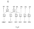
- FIG. 8 shows an embodiment of an optical switching unit OS of FIG optical signal distribution device from Fig. 7.
- the optical switching unit OS includes six optical switches and two optical combiners. In order to all three examples described for FIG. 7 can be realized.
- Example 1 is realized by all switch positions on the left output are switched.
- Another example would be the optical one Cablephone signals CABLE1 and the video-on-demand signals VOD1 to switch the optical splitter SP2 and the optical Cablephone signals CABLE2 and the video-on-demand signals VOD2 the optical splitter SP3.
Landscapes
- Engineering & Computer Science (AREA)
- Computing Systems (AREA)
- Physics & Mathematics (AREA)
- Electromagnetism (AREA)
- Computer Networks & Wireless Communication (AREA)
- Signal Processing (AREA)
- Optical Communication System (AREA)
- Two-Way Televisions, Distribution Of Moving Picture Or The Like (AREA)
Abstract
Description
- Fig. 1
- eine schematische Darstellung eines ersten erfindungsgemäßen Systems zur optischen Übertragung von Informationen,
- Fig. 2
- eine schematische Darstellung eines zweiten erfindungsgemäßen Systems zur optischen Übertragung von Informationen,
- Fig. 3
- eine schematische Darstellung eines dritten erfindungsgemäßen Systems zur optischen Übertragung von Informationen,
- Fig. 4
- ein schematisch dargestellter Aufbau eines Ausschnittes der optischen Netzabschlußeinheit aus Fig. 3,
- Fig. 5
- eine schematische Darstellung eines vierten erfindungsgemäßen Systems zur optischen Übertragung von Informationen,
- Fig. 6
- einen schematisch dargestellten Aufbau einer erfindungsgemäßen optischen Signalverteileinrichtung des Systems aus Fig. 5,
- Fig. 7
- einen schematisch dargestellten Aufbau einer weiteren erfindungsgemäßen optischen Signalverteileinrichtung des Systems aus Fig. 5, und
- Fig. 8
- eine Ausführungsform einer optischen Schalteinheit der optischen Signalverteileinrichtung aus Fig. 7.
Claims (12)
- System ( SYS ) zur optischen Übertragung von Informationen von einer Unterzentrale ( HUB ) über mehrere optische Übertragungsleitungen zu mehreren optischen Netzabschlußeinheiten ( ONU ), wobei das System ( SYS ) mindestens ein Mittel (K1,..., Km) zur optischen Übertragung von weiteren Informationen und mindestens einen optischen Koppler (C1, C2, SP1, SP2, SP3, SP4, SP5, SP6, SP7 ) beinhaltet, und wobei die weiteren Informationen eines jeden Mittels (K1,..., Km ) jeweils über einen optischen Koppler ( C1, C2, SP1, SP2, SP3, SP4, SP5, SP6, SP7 ) in eine optische Übertragungsleitung eingespeist werden, die nur mit einem Teil der mehreren optischen Netzabschlußeinheiten ( ONU ) verbunden ist,
dadurch gekennzeichnet,
daß eine optische Signalverteileinrichtung (VER) vorgesehen ist, um die Informationen (CATV) und die weiteren Informationen ( CABLE, NVOD, VOD ) zu verknüpfen und sie anschließend gemeinsam zu dem jeweiligen Teil der mehreren optischen Netzabschlußeinheiten (ONU) zu übertragen, daß die optische Signalverteileinrichtung (VER) mindestens drei optische Koppler (SP1, SP2, SP3 ) beinhaltet, von denen mindestens zwei ( SP2, SP3 ) zwei Eingänge und zwei Ausgänge aufweisen, daß die Informationen einem ( SP1 ) der mindestens drei optischen Koppler (SP1, SP2, SP3 ) zugeführt werden, der mit zwei der mindestens zwei optischen Koppler ( SP2, SP3 ) mit zwei Eingängen verbunden ist, und daß die weiteren Informationen ( CABLE, NVOD, VOD ) mindestens einem der mindestens zwei optischen Koppler ( SP2, SP3 ) mit zwei Eingängen zugeführt werden, um sie mit den Informationen (CATV) der Unterzentrale ( HUB ) zu verknüpfen. - System ( SYS ) nach Anspruch 1, dadurch gekennzeichnet, daß eine optische Schalteinheit (OS) vorgesehen ist, um die Zuordnung der weiteren Informationen ( CABLE, NVOD, VOD ) zu dem mindestens einen Eingang eines der optischen Koppler ( SP1, SP2, SP3 ) zu steuern.
- System ( SYS ) nach Anspruch 1 oder 2, dadurch gekennzeichnet, daß daß in der Unterzentrale ( HUB ) und in dem mindestens einem Mittel (K1,..., Km) jeweils ein Elektrisch/Optisch-Umsetzer ( E/O ) vorgesehen ist, um elektrische Signale in optische umzusetzen, wobei die optischen Signale dieselbe Wellenlänge besitzen, und wobei sich die Frequenzbereiche der elektrischen Signale in der Unterzentrale (HUB) und in dem mindestens einem Mittel (K1,..., Km ) derart gewählt sind, daß sie sich nicht überschneiden.
- System (SYS) nach Anspruch 1,2 oder 3, dadurch gekennzeichnet, daß die mehreren optischen Netzabschlußeinheiten ( ONU) zur Übertragung von Informationen über weitere optische Übertragungsleitungen mit dem mindestens einem Mittel (K1,..., Km ) verbunden sind.
- System ( SYS ) nach Anspruch 4, dadurch gekennzeichnet, daß das mindestens eine Mittel ( K1, ..., Km ) mit der Unterzentrale ( HUB) verbunden sind, und daß das midenstens eine Mittel (K1,..., Km ) Mittel zur Aufteilung der von den mehreren optischen Netzabschlußeinheiten ( ONU) empfangenen Informationen und Mittel zur Weiterleitung eines Teils der von den optischen Netzabschlußeinheiten (ONU) empfangenen Informationen zur Unterzentrale ( HUB ) beinhalten.
- System ( SYS ) nach Anspruch 1, dadurch gekennzeichnet, daß die Unterzentrale ( HUB ) eine Kabelfernsehkopfstation ist, die Informationen Fernsehsignale sind und die Kabelfernsehkopfstation über ein optisches Verteilnetz mit mindestens einem optischen Splitter mit den mehreren optischen Netzabschlußeinheiten ( ONU) verbunden ist.
- System ( SYS ) nach Anspruch 6, dadurch gekennzeichnet, daß die weiteren Informationen Fernsprechsignale sind, daß das midestens eine Mittel ( K1, ..., Km ) mit einem Fernsprechnetz (NET) und die mehreren optischen Netzabschlußeinheiten ( ONU) jeweils mit einer Gruppe von Endstellen ( END ) verbindbar sind, und daß über jedes Mittel (K1, ..., Km ) Fernsprechsignale zu wenigstens einer Gruppe von Endstellen ( END ) übertragen werden.
- System ( SYS ) nach den Ansprüchen 5 und 7, dadurch gekennzeichnet, daß die von den mehreren optischen Netzabschlußeinheiten ( ONU) zu übertragenden Informationen interaktive Abrufsignale und Fernsprechsignale sind, und daß die interaktiven Abrufsignale zur Unterzentrale ( HUB ) und die Fernsprechsignale zum Fernsprechnetz (NET) übertragen werden.
- System ( SYS ) nach Anspruch 7, dadurch gekennzeichnet, daß das die mehreren optischen Netzabschlußeinheiten ( ONU) zur Unterdrückung von Störungen jeweils mindestens einen Schalter (S1, S2) beinhalten, mittels dessen zumindest ein Teil des Frequenzbereichs, der zur Informationsübertragung zu dem jeweiligen Mittel (K1,..., Km ) dient, für die Übertragung gesperrt wird, für den Fall, daß in diesem Teil des Frequenzbereichs keine Übertragung stattfinden soll.
- System ( SYS ) nach Anspruch 9, dadurch gekennzeichnet, daß das die mehreren optischen Netzabschlußeinheiten (ONU) jeweils mindestens zwei Mittel ( BP1, BP2 ) zur Aufteilung des Frequenzbereichs, der zur Informationsübertragung zu dem jeweiligen Mittel (K1,..., Km ) dient, und eine Steuereinheit ( CTRL ) zur Detektion der Signalpegel in den aufgeteilten Frequenzbereichen und zur Ansteuerung des mindestens einen Schalter (S1, S2) beinhalten, und daß die Ansteuerung des mindestens einen Schalters (S1, S2) derart erfolgt, daß für den Fall, daß der entsprechende Signalpegel unterhalb einer vorgegebenen unteren Schwelle oder überhalb einer vorgegebenen oberen Schwelle liegt, der entsprechende Frequenzbereich gesperrt wird.
- System ( SYS ) nach Anspruch 1, dadurch gekennzeichnet, daß die von der Unterzentrale (HUB) übertragenen Informationen und die von dem midestens einem Mittel (K1,..., Km ) übertragenen weiteren Informationen bei unterschiedlichen Wellenlängen übertragen werden.
- Optische Signalverteileinrichtung (VER) eines optischen Übertragungssystems (SYS) zur Übertragung von mindestens drei unterschiedlichen Informationen ( CATV, CABLE1, CABLE2 ), beinhaltend mindestens drei optische Koppler ( SP1, SP2, SP3 ), von denen mindestens zwei ( SP2, SP3 ) zwei Eingänge und zwei Ausgänge aufweisen, daß erste Informationen einem ( SP1 ) der mindestens drei optischen Koppler ( SP1, SP2, SP3 ) zugeführt werden, der mit zwei der mindestens zwei optischen Koppler ( SP2, SP3 ) mit zwei Eingängen verbunden ist, daß zweite Informationen ( CABLE, NVOD, VOD ) mindestens einem ( SP2) der mindestens zwei optischen Koppler ( SP2, SP3 ) mit zwei Eingängen zugeführt werden, um sie mit den ersten Informationen (CATV) zu verknüpfen, und daß dritte Informationen ( CABLE, NVOD, VOD ) mindestens einem ( SP3) der mindestens zwei optischen Koppler ( SP2, SP3 ) mit zwei Eingängen zugeführt werden, um sie mit den ersten Informationen ( CATV) zu verknüpfen.
Applications Claiming Priority (2)
| Application Number | Priority Date | Filing Date | Title |
|---|---|---|---|
| DE19719425 | 1997-05-12 | ||
| DE19719425A DE19719425A1 (de) | 1997-05-12 | 1997-05-12 | System zur optischen Übertragung von Informationen |
Publications (3)
| Publication Number | Publication Date |
|---|---|
| EP0881791A2 true EP0881791A2 (de) | 1998-12-02 |
| EP0881791A3 EP0881791A3 (de) | 2003-09-10 |
| EP0881791B1 EP0881791B1 (de) | 2005-02-23 |
Family
ID=7828980
Family Applications (1)
| Application Number | Title | Priority Date | Filing Date |
|---|---|---|---|
| EP98440087A Expired - Lifetime EP0881791B1 (de) | 1997-05-12 | 1998-05-07 | System zur optischen Übertragung von Informationen |
Country Status (7)
| Country | Link |
|---|---|
| US (1) | US6144471A (de) |
| EP (1) | EP0881791B1 (de) |
| CN (1) | CN1130868C (de) |
| AU (1) | AU736033B2 (de) |
| CA (1) | CA2235080A1 (de) |
| DE (2) | DE19719425A1 (de) |
| ES (1) | ES2235304T3 (de) |
Families Citing this family (12)
| Publication number | Priority date | Publication date | Assignee | Title |
|---|---|---|---|---|
| DE19701888A1 (de) * | 1997-01-21 | 1998-07-23 | Alsthom Cge Alcatel | System zur optischen Übertragung von Informationen |
| US6577414B1 (en) * | 1998-02-20 | 2003-06-10 | Lucent Technologies Inc. | Subcarrier modulation fiber-to-the-home/curb (FTTH/C) access system providing broadband communications |
| DE19959813B4 (de) * | 1999-12-11 | 2004-02-05 | Alcatel | Synchrones digitales Nachrichtenübertragungssystem |
| US7181142B1 (en) * | 2002-04-09 | 2007-02-20 | Time Warner Cable Inc. | Broadband optical network apparatus and method |
| US20070091812A1 (en) * | 2005-10-24 | 2007-04-26 | Sbc Knowledge Ventures L.P. | Communication system and method utilizing a satellite network |
| KR101548176B1 (ko) * | 2009-02-02 | 2015-08-31 | 삼성전자주식회사 | 메모리 시스템, 메모리 테스트 시스템 및 이의 테스트 방법 |
| US9948399B2 (en) | 2015-01-09 | 2018-04-17 | Time Warner Cable Enterprises Llc | Methods and apparatus for removing beat interference from splitters/combiners |
| US9674591B2 (en) | 2015-06-08 | 2017-06-06 | Time Warner Cable Enterprises Llc | Methods and apparatus for asymmetric distribution of mixed content via a network |
| US12294820B1 (en) | 2024-08-12 | 2025-05-06 | Frontier Communications Holdings, Llc | Systems and methods for providing route redundancy in networking systems |
| US12294819B1 (en) | 2024-08-12 | 2025-05-06 | Frontier Communications Holdings, Llc | Systems and methods for external ethernet qualification |
| US12483814B1 (en) * | 2024-08-12 | 2025-11-25 | Frontier Communications Holdings, Llc | Systems and methods for qualifying on-ramp facilities in networking systems |
| US12294407B1 (en) | 2024-08-12 | 2025-05-06 | Frontier Communications Holdings, Llc | Systems and methods for fiber upstream trace determination |
Family Cites Families (5)
| Publication number | Priority date | Publication date | Assignee | Title |
|---|---|---|---|---|
| US5321541A (en) * | 1991-12-12 | 1994-06-14 | At&T Bell Laboratories | Passive optical communication network with broadband upgrade |
| US5579143A (en) * | 1993-06-04 | 1996-11-26 | Ciena Corporation | Optical system with tunable in-fiber gratings |
| WO1995005041A1 (en) * | 1993-08-04 | 1995-02-16 | British Telecommunications Public Limited Company | Optical fibre communications system |
| DE19505578A1 (de) * | 1995-02-18 | 1996-08-22 | Sel Alcatel Ag | Optisches Übertragungssystem für Kabelfernsehsignale und Video- und Telekommunikationssignale |
| US5933437A (en) * | 1996-09-26 | 1999-08-03 | Lucent Technologies Inc. | Optical fiber laser |
-
1997
- 1997-05-12 DE DE19719425A patent/DE19719425A1/de not_active Withdrawn
-
1998
- 1998-05-04 AU AU63769/98A patent/AU736033B2/en not_active Ceased
- 1998-05-04 US US09/072,281 patent/US6144471A/en not_active Expired - Fee Related
- 1998-05-07 ES ES98440087T patent/ES2235304T3/es not_active Expired - Lifetime
- 1998-05-07 DE DE59812587T patent/DE59812587D1/de not_active Expired - Fee Related
- 1998-05-07 EP EP98440087A patent/EP0881791B1/de not_active Expired - Lifetime
- 1998-05-11 CA CA002235080A patent/CA2235080A1/en not_active Abandoned
- 1998-05-11 CN CN98108417A patent/CN1130868C/zh not_active Expired - Fee Related
Also Published As
| Publication number | Publication date |
|---|---|
| DE59812587D1 (de) | 2005-03-31 |
| AU736033B2 (en) | 2001-07-26 |
| EP0881791A3 (de) | 2003-09-10 |
| US6144471A (en) | 2000-11-07 |
| CN1130868C (zh) | 2003-12-10 |
| EP0881791B1 (de) | 2005-02-23 |
| CA2235080A1 (en) | 1998-11-12 |
| AU6376998A (en) | 1998-11-12 |
| CN1199291A (zh) | 1998-11-18 |
| ES2235304T3 (es) | 2005-07-01 |
| DE19719425A1 (de) | 1998-11-19 |
Similar Documents
| Publication | Publication Date | Title |
|---|---|---|
| EP0727889B1 (de) | Optisches Übertragungssystem für Kabelfernsehsignale und Video- und Telekommunikationssignale | |
| EP0151454B1 (de) | Breitbandiges integriertes Teilnehmeranschlusssystem | |
| DE69010011T2 (de) | Kommunikationssystem. | |
| DE69533538T2 (de) | Optisches Kommunikations-Zugangs-Netzwerk mit einem Multiplexer/Demultiplexer in jeder Netzabschlusseinrichtung | |
| DE19841775B4 (de) | Teilnehmernetz mit optischer Faser | |
| DE69024006T2 (de) | Dynamisch reagierendes Kabelfernsehsystem mit mehrfach genutzter faseroptischer Verbindung. | |
| DE69719912T2 (de) | Netzwerkgerät und Methode zum Liefern von komprimierten digitalen Videosignalen über Minifaserknotenpunkte | |
| DE2807986A1 (de) | Anlage fuer interaktives kabelfernsehen | |
| EP0499065A2 (de) | Optisches Nachrichtenübertragungssystem für den Teilnehmeranschlussbereich mit optischen Verstärkern | |
| EP0817410A2 (de) | Endgerät für ein optisches Netz, optisches Netz und Endvermittlungsstelle hierfür | |
| EP0881791B1 (de) | System zur optischen Übertragung von Informationen | |
| DE60215222T2 (de) | Hybrider faseroptischer und koaxialkabelnetzwerkknoten mit einem kabelmodemabschlusssystem | |
| EP0386482B1 (de) | Optisches Nachrichtenübertragungssystem für den Teilnehmeranschlussbereich | |
| EP0972367B1 (de) | Zugangsnetz zur übertragung von optischen signalen | |
| DE69433916T2 (de) | Verfahren und vorrichtung zur bereitstellung eines geschützten telefondienstes über ein hybrides koaxialkabelnetz | |
| DE69513534T2 (de) | Hybrides faser-/koaxial kommunikationssystem für bild- und fernsprechsignalen | |
| DE60106736T2 (de) | Weichenanordnung mit wellenleitergitter und mehreren eingängen für broadcast- und multicastdienste | |
| EP0854597B1 (de) | System zur optischen Übertragung von Informationen über mehrere optische Übertragungsleitungen | |
| DE3403206A1 (de) | Lichtwellenleiter-verteilnetz fuer fernseh- und tonprogramme | |
| EP0786176B1 (de) | Hybrides lichtwellenleiter- und koaxialleitungs- teilnehmeranschlussnetz | |
| DE60113960T2 (de) | Zweiwegnetzwerk zur Verteilung von Kabel-TV-Signalen an Endpunkte mittels optischer Fasern | |
| EP0706292A1 (de) | Schaltungsanordnung zur Steuerung der Übertragung von Informationen für interaktive Dienste | |
| EP0760584B1 (de) | Elektrische Übertragungssystem, mit einem Breitbandverteilnetz für TV- und Audio-Signale, und mit einer Möglichkeit für interaktive Dienste | |
| DE10344753B4 (de) | Verfahren zum bidirektionalen Übertragen von elektronischen Daten in einem Fernsehdaten-Kabelnetzwerk | |
| EP0469382B1 (de) | Übertragungseinrichtung zur Übertragung von Nachrichten und von zusätzlichen Signalen |
Legal Events
| Date | Code | Title | Description |
|---|---|---|---|
| PUAI | Public reference made under article 153(3) epc to a published international application that has entered the european phase |
Free format text: ORIGINAL CODE: 0009012 |
|
| AK | Designated contracting states |
Kind code of ref document: A2 Designated state(s): AT BE CH CY DE DK ES FI FR GB GR IE IT LI LU MC NL PT SE |
|
| AX | Request for extension of the european patent |
Free format text: AL;LT;LV;MK;RO;SI |
|
| RAP3 | Party data changed (applicant data changed or rights of an application transferred) |
Owner name: ALCATEL |
|
| PUAL | Search report despatched |
Free format text: ORIGINAL CODE: 0009013 |
|
| AK | Designated contracting states |
Kind code of ref document: A3 Designated state(s): AT BE CH CY DE DK ES FI FR GB GR IE IT LI LU MC NL PT SE |
|
| AX | Request for extension of the european patent |
Extension state: AL LT LV MK RO SI |
|
| 17P | Request for examination filed |
Effective date: 20031008 |
|
| 17Q | First examination report despatched |
Effective date: 20031222 |
|
| AKX | Designation fees paid |
Designated state(s): BE DE ES FR GB IT SE |
|
| GRAP | Despatch of communication of intention to grant a patent |
Free format text: ORIGINAL CODE: EPIDOSNIGR1 |
|
| GRAS | Grant fee paid |
Free format text: ORIGINAL CODE: EPIDOSNIGR3 |
|
| GRAA | (expected) grant |
Free format text: ORIGINAL CODE: 0009210 |
|
| AK | Designated contracting states |
Kind code of ref document: B1 Designated state(s): BE DE ES FR GB IT SE |
|
| REG | Reference to a national code |
Ref country code: GB Ref legal event code: FG4D Free format text: NOT ENGLISH |
|
| GBT | Gb: translation of ep patent filed (gb section 77(6)(a)/1977) |
Effective date: 20050223 |
|
| REG | Reference to a national code |
Ref country code: IE Ref legal event code: FG4D Free format text: GERMAN |
|
| REF | Corresponds to: |
Ref document number: 59812587 Country of ref document: DE Date of ref document: 20050331 Kind code of ref document: P |
|
| PG25 | Lapsed in a contracting state [announced via postgrant information from national office to epo] |
Ref country code: SE Free format text: LAPSE BECAUSE OF FAILURE TO SUBMIT A TRANSLATION OF THE DESCRIPTION OR TO PAY THE FEE WITHIN THE PRESCRIBED TIME-LIMIT Effective date: 20050523 |
|
| PG25 | Lapsed in a contracting state [announced via postgrant information from national office to epo] |
Ref country code: BE Free format text: LAPSE BECAUSE OF NON-PAYMENT OF DUE FEES Effective date: 20050531 |
|
| REG | Reference to a national code |
Ref country code: ES Ref legal event code: FG2A Ref document number: 2235304 Country of ref document: ES Kind code of ref document: T3 |
|
| BERE | Be: lapsed |
Owner name: ALCATEL Effective date: 20050531 |
|
| ET | Fr: translation filed | ||
| PLBE | No opposition filed within time limit |
Free format text: ORIGINAL CODE: 0009261 |
|
| STAA | Information on the status of an ep patent application or granted ep patent |
Free format text: STATUS: NO OPPOSITION FILED WITHIN TIME LIMIT |
|
| 26N | No opposition filed |
Effective date: 20051124 |
|
| BERE | Be: lapsed |
Owner name: ALCATEL Effective date: 20050531 |
|
| PGFP | Annual fee paid to national office [announced via postgrant information from national office to epo] |
Ref country code: ES Payment date: 20080529 Year of fee payment: 11 Ref country code: DE Payment date: 20080523 Year of fee payment: 11 |
|
| PGFP | Annual fee paid to national office [announced via postgrant information from national office to epo] |
Ref country code: IT Payment date: 20080524 Year of fee payment: 11 |
|
| PGFP | Annual fee paid to national office [announced via postgrant information from national office to epo] |
Ref country code: GB Payment date: 20080522 Year of fee payment: 11 |
|
| GBPC | Gb: european patent ceased through non-payment of renewal fee |
Effective date: 20090507 |
|
| REG | Reference to a national code |
Ref country code: FR Ref legal event code: ST Effective date: 20100129 |
|
| PG25 | Lapsed in a contracting state [announced via postgrant information from national office to epo] |
Ref country code: FR Free format text: LAPSE BECAUSE OF NON-PAYMENT OF DUE FEES Effective date: 20090602 |
|
| PGFP | Annual fee paid to national office [announced via postgrant information from national office to epo] |
Ref country code: FR Payment date: 20080526 Year of fee payment: 11 |
|
| PG25 | Lapsed in a contracting state [announced via postgrant information from national office to epo] |
Ref country code: GB Free format text: LAPSE BECAUSE OF NON-PAYMENT OF DUE FEES Effective date: 20090507 |
|
| PG25 | Lapsed in a contracting state [announced via postgrant information from national office to epo] |
Ref country code: DE Free format text: LAPSE BECAUSE OF NON-PAYMENT OF DUE FEES Effective date: 20091201 |
|
| REG | Reference to a national code |
Ref country code: ES Ref legal event code: FD2A Effective date: 20090508 |
|
| PG25 | Lapsed in a contracting state [announced via postgrant information from national office to epo] |
Ref country code: ES Free format text: LAPSE BECAUSE OF NON-PAYMENT OF DUE FEES Effective date: 20090508 |
|
| PG25 | Lapsed in a contracting state [announced via postgrant information from national office to epo] |
Ref country code: IT Free format text: LAPSE BECAUSE OF NON-PAYMENT OF DUE FEES Effective date: 20090507 |