EP0881992B1 - Verfahren und vorrichtung zum schmelzen von körnformige materialen - Google Patents
Verfahren und vorrichtung zum schmelzen von körnformige materialen Download PDFInfo
- Publication number
- EP0881992B1 EP0881992B1 EP97900366A EP97900366A EP0881992B1 EP 0881992 B1 EP0881992 B1 EP 0881992B1 EP 97900366 A EP97900366 A EP 97900366A EP 97900366 A EP97900366 A EP 97900366A EP 0881992 B1 EP0881992 B1 EP 0881992B1
- Authority
- EP
- European Patent Office
- Prior art keywords
- cavity
- crucible
- melted
- microwave
- melting
- Prior art date
- Legal status (The legal status is an assumption and is not a legal conclusion. Google has not performed a legal analysis and makes no representation as to the accuracy of the status listed.)
- Expired - Lifetime
Links
- 238000000034 method Methods 0.000 title claims description 36
- 238000002844 melting Methods 0.000 title claims description 33
- 230000008018 melting Effects 0.000 title claims description 33
- 239000011236 particulate material Substances 0.000 title abstract description 5
- 239000000463 material Substances 0.000 claims abstract description 205
- 238000001816 cooling Methods 0.000 claims abstract description 24
- 239000000155 melt Substances 0.000 claims description 52
- 239000011521 glass Substances 0.000 claims description 34
- 239000002245 particle Substances 0.000 claims description 21
- 230000006698 induction Effects 0.000 claims description 17
- 238000010079 rubber tapping Methods 0.000 claims description 12
- 230000015572 biosynthetic process Effects 0.000 claims description 11
- VTYYLEPIZMXCLO-UHFFFAOYSA-L Calcium carbonate Chemical compound [Ca+2].[O-]C([O-])=O VTYYLEPIZMXCLO-UHFFFAOYSA-L 0.000 claims description 6
- CDBYLPFSWZWCQE-UHFFFAOYSA-L Sodium Carbonate Chemical compound [Na+].[Na+].[O-]C([O-])=O CDBYLPFSWZWCQE-UHFFFAOYSA-L 0.000 claims description 6
- 230000003247 decreasing effect Effects 0.000 claims description 5
- 239000012530 fluid Substances 0.000 claims description 5
- 239000011800 void material Substances 0.000 claims description 5
- 238000007496 glass forming Methods 0.000 claims description 4
- 239000004576 sand Substances 0.000 claims description 4
- 238000007711 solidification Methods 0.000 claims description 4
- 229910000019 calcium carbonate Inorganic materials 0.000 claims description 3
- 230000005484 gravity Effects 0.000 claims description 3
- 235000012204 lemonade/lime carbonate Nutrition 0.000 claims description 3
- 239000004571 lime Substances 0.000 claims description 3
- 229910000029 sodium carbonate Inorganic materials 0.000 claims description 3
- 239000004615 ingredient Substances 0.000 claims description 2
- 239000000289 melt material Substances 0.000 claims description 2
- 239000013589 supplement Substances 0.000 claims description 2
- 239000002699 waste material Substances 0.000 abstract description 20
- XKRFYHLGVUSROY-UHFFFAOYSA-N Argon Chemical compound [Ar] XKRFYHLGVUSROY-UHFFFAOYSA-N 0.000 abstract description 16
- 239000007789 gas Substances 0.000 abstract description 12
- 229910052786 argon Inorganic materials 0.000 abstract description 8
- 230000008901 benefit Effects 0.000 abstract description 4
- 238000004140 cleaning Methods 0.000 abstract description 4
- 238000005265 energy consumption Methods 0.000 abstract description 2
- 210000003625 skull Anatomy 0.000 description 27
- 238000010438 heat treatment Methods 0.000 description 21
- 230000008569 process Effects 0.000 description 10
- OKTJSMMVPCPJKN-UHFFFAOYSA-N Carbon Chemical compound [C] OKTJSMMVPCPJKN-UHFFFAOYSA-N 0.000 description 7
- 229910002804 graphite Inorganic materials 0.000 description 7
- 239000010439 graphite Substances 0.000 description 7
- 239000000203 mixture Substances 0.000 description 6
- 239000006060 molten glass Substances 0.000 description 6
- 239000003039 volatile agent Substances 0.000 description 6
- 229910052751 metal Inorganic materials 0.000 description 4
- 239000002184 metal Substances 0.000 description 4
- 230000007704 transition Effects 0.000 description 4
- XLYOFNOQVPJJNP-UHFFFAOYSA-N water Substances O XLYOFNOQVPJJNP-UHFFFAOYSA-N 0.000 description 4
- 230000004888 barrier function Effects 0.000 description 3
- 239000002585 base Substances 0.000 description 3
- 239000000919 ceramic Substances 0.000 description 3
- 238000005816 glass manufacturing process Methods 0.000 description 3
- 239000007788 liquid Substances 0.000 description 3
- 239000011159 matrix material Substances 0.000 description 3
- 238000002156 mixing Methods 0.000 description 3
- 239000012768 molten material Substances 0.000 description 3
- 239000010453 quartz Substances 0.000 description 3
- VYPSYNLAJGMNEJ-UHFFFAOYSA-N silicon dioxide Inorganic materials O=[Si]=O VYPSYNLAJGMNEJ-UHFFFAOYSA-N 0.000 description 3
- 238000004017 vitrification Methods 0.000 description 3
- 230000009471 action Effects 0.000 description 2
- PNEYBMLMFCGWSK-UHFFFAOYSA-N aluminium oxide Inorganic materials [O-2].[O-2].[O-2].[Al+3].[Al+3] PNEYBMLMFCGWSK-UHFFFAOYSA-N 0.000 description 2
- 238000006243 chemical reaction Methods 0.000 description 2
- 238000007599 discharging Methods 0.000 description 2
- 230000000694 effects Effects 0.000 description 2
- 239000012466 permeate Substances 0.000 description 2
- 239000000047 product Substances 0.000 description 2
- 230000005855 radiation Effects 0.000 description 2
- 238000003860 storage Methods 0.000 description 2
- WHXSMMKQMYFTQS-UHFFFAOYSA-N Lithium Chemical compound [Li] WHXSMMKQMYFTQS-UHFFFAOYSA-N 0.000 description 1
- ZLMJMSJWJFRBEC-UHFFFAOYSA-N Potassium Chemical compound [K] ZLMJMSJWJFRBEC-UHFFFAOYSA-N 0.000 description 1
- 230000002378 acidificating effect Effects 0.000 description 1
- 229910000287 alkaline earth metal oxide Inorganic materials 0.000 description 1
- 229910052792 caesium Inorganic materials 0.000 description 1
- TVFDJXOCXUVLDH-UHFFFAOYSA-N caesium atom Chemical compound [Cs] TVFDJXOCXUVLDH-UHFFFAOYSA-N 0.000 description 1
- 230000008859 change Effects 0.000 description 1
- 238000009833 condensation Methods 0.000 description 1
- 230000005494 condensation Effects 0.000 description 1
- 239000004020 conductor Substances 0.000 description 1
- 238000010276 construction Methods 0.000 description 1
- 239000000498 cooling water Substances 0.000 description 1
- 230000007423 decrease Effects 0.000 description 1
- 239000003517 fume Substances 0.000 description 1
- 239000011261 inert gas Substances 0.000 description 1
- 239000011810 insulating material Substances 0.000 description 1
- 229910000464 lead oxide Inorganic materials 0.000 description 1
- 229910001947 lithium oxide Inorganic materials 0.000 description 1
- 238000010309 melting process Methods 0.000 description 1
- 230000003287 optical effect Effects 0.000 description 1
- 239000005304 optical glass Substances 0.000 description 1
- 229920000573 polyethylene Polymers 0.000 description 1
- 239000011591 potassium Substances 0.000 description 1
- 229910001950 potassium oxide Inorganic materials 0.000 description 1
- 239000000843 powder Substances 0.000 description 1
- 238000002360 preparation method Methods 0.000 description 1
- 239000002901 radioactive waste Substances 0.000 description 1
- 238000004064 recycling Methods 0.000 description 1
- 230000000630 rising effect Effects 0.000 description 1
- 238000007789 sealing Methods 0.000 description 1
- 238000000926 separation method Methods 0.000 description 1
- 229910052712 strontium Inorganic materials 0.000 description 1
- CIOAGBVUUVVLOB-UHFFFAOYSA-N strontium atom Chemical compound [Sr] CIOAGBVUUVVLOB-UHFFFAOYSA-N 0.000 description 1
- 231100000331 toxic Toxicity 0.000 description 1
- 230000002588 toxic effect Effects 0.000 description 1
Images

Classifications
-
- G—PHYSICS
- G21—NUCLEAR PHYSICS; NUCLEAR ENGINEERING
- G21F—PROTECTION AGAINST X-RADIATION, GAMMA RADIATION, CORPUSCULAR RADIATION OR PARTICLE BOMBARDMENT; TREATING RADIOACTIVELY CONTAMINATED MATERIAL; DECONTAMINATION ARRANGEMENTS THEREFOR
- G21F9/00—Treating radioactively contaminated material; Decontamination arrangements therefor
- G21F9/28—Treating solids
- G21F9/30—Processing
- G21F9/301—Processing by fixation in stable solid media
- G21F9/302—Processing by fixation in stable solid media in an inorganic matrix
- G21F9/305—Glass or glass like matrix
-
- C—CHEMISTRY; METALLURGY
- C03—GLASS; MINERAL OR SLAG WOOL
- C03B—MANUFACTURE, SHAPING, OR SUPPLEMENTARY PROCESSES
- C03B5/00—Melting in furnaces; Furnaces so far as specially adapted for glass manufacture
- C03B5/04—Melting in furnaces; Furnaces so far as specially adapted for glass manufacture in tank furnaces
-
- C—CHEMISTRY; METALLURGY
- C03—GLASS; MINERAL OR SLAG WOOL
- C03B—MANUFACTURE, SHAPING, OR SUPPLEMENTARY PROCESSES
- C03B5/00—Melting in furnaces; Furnaces so far as specially adapted for glass manufacture
- C03B5/005—Melting in furnaces; Furnaces so far as specially adapted for glass manufacture of glass-forming waste materials
-
- C—CHEMISTRY; METALLURGY
- C03—GLASS; MINERAL OR SLAG WOOL
- C03B—MANUFACTURE, SHAPING, OR SUPPLEMENTARY PROCESSES
- C03B5/00—Melting in furnaces; Furnaces so far as specially adapted for glass manufacture
- C03B5/02—Melting in furnaces; Furnaces so far as specially adapted for glass manufacture in electric furnaces, e.g. by dielectric heating
- C03B5/023—Melting in furnaces; Furnaces so far as specially adapted for glass manufacture in electric furnaces, e.g. by dielectric heating by microwave heating
-
- C—CHEMISTRY; METALLURGY
- C03—GLASS; MINERAL OR SLAG WOOL
- C03B—MANUFACTURE, SHAPING, OR SUPPLEMENTARY PROCESSES
- C03B5/00—Melting in furnaces; Furnaces so far as specially adapted for glass manufacture
- C03B5/02—Melting in furnaces; Furnaces so far as specially adapted for glass manufacture in electric furnaces, e.g. by dielectric heating
- C03B5/025—Melting in furnaces; Furnaces so far as specially adapted for glass manufacture in electric furnaces, e.g. by dielectric heating by arc discharge or plasma heating
-
- C—CHEMISTRY; METALLURGY
- C03—GLASS; MINERAL OR SLAG WOOL
- C03B—MANUFACTURE, SHAPING, OR SUPPLEMENTARY PROCESSES
- C03B5/00—Melting in furnaces; Furnaces so far as specially adapted for glass manufacture
- C03B5/16—Special features of the melting process; Auxiliary means specially adapted for glass-melting furnaces
-
- F—MECHANICAL ENGINEERING; LIGHTING; HEATING; WEAPONS; BLASTING
- F23—COMBUSTION APPARATUS; COMBUSTION PROCESSES
- F23G—CREMATION FURNACES; CONSUMING WASTE PRODUCTS BY COMBUSTION
- F23G5/00—Incineration of waste; Incinerator constructions; Details, accessories or control therefor
- F23G5/08—Incineration of waste; Incinerator constructions; Details, accessories or control therefor having supplementary heating
- F23G5/085—High-temperature heating means, e.g. plasma, for partly melting the waste
-
- F—MECHANICAL ENGINEERING; LIGHTING; HEATING; WEAPONS; BLASTING
- F27—FURNACES; KILNS; OVENS; RETORTS
- F27B—FURNACES, KILNS, OVENS OR RETORTS IN GENERAL; OPEN SINTERING OR LIKE APPARATUS
- F27B14/00—Crucible or pot furnaces
- F27B14/08—Details specially adapted for crucible or pot furnaces
- F27B14/14—Arrangements of heating devices
-
- F—MECHANICAL ENGINEERING; LIGHTING; HEATING; WEAPONS; BLASTING
- F27—FURNACES; KILNS; OVENS; RETORTS
- F27D—DETAILS OR ACCESSORIES OF FURNACES, KILNS, OVENS OR RETORTS, IN SO FAR AS THEY ARE OF KINDS OCCURRING IN MORE THAN ONE KIND OF FURNACE
- F27D11/00—Arrangement of elements for electric heating in or on furnaces
- F27D11/08—Heating by electric discharge, e.g. arc discharge
-
- F—MECHANICAL ENGINEERING; LIGHTING; HEATING; WEAPONS; BLASTING
- F27—FURNACES; KILNS; OVENS; RETORTS
- F27D—DETAILS OR ACCESSORIES OF FURNACES, KILNS, OVENS OR RETORTS, IN SO FAR AS THEY ARE OF KINDS OCCURRING IN MORE THAN ONE KIND OF FURNACE
- F27D11/00—Arrangement of elements for electric heating in or on furnaces
- F27D11/12—Arrangement of elements for electric heating in or on furnaces with electromagnetic fields acting directly on the material being heated
-
- H—ELECTRICITY
- H05—ELECTRIC TECHNIQUES NOT OTHERWISE PROVIDED FOR
- H05B—ELECTRIC HEATING; ELECTRIC LIGHT SOURCES NOT OTHERWISE PROVIDED FOR; CIRCUIT ARRANGEMENTS FOR ELECTRIC LIGHT SOURCES, IN GENERAL
- H05B6/00—Heating by electric, magnetic or electromagnetic fields
- H05B6/64—Heating using microwaves
- H05B6/80—Apparatus for specific applications
-
- F—MECHANICAL ENGINEERING; LIGHTING; HEATING; WEAPONS; BLASTING
- F23—COMBUSTION APPARATUS; COMBUSTION PROCESSES
- F23G—CREMATION FURNACES; CONSUMING WASTE PRODUCTS BY COMBUSTION
- F23G2204/00—Supplementary heating arrangements
- F23G2204/20—Supplementary heating arrangements using electric energy
- F23G2204/203—Microwave
-
- H—ELECTRICITY
- H05—ELECTRIC TECHNIQUES NOT OTHERWISE PROVIDED FOR
- H05B—ELECTRIC HEATING; ELECTRIC LIGHT SOURCES NOT OTHERWISE PROVIDED FOR; CIRCUIT ARRANGEMENTS FOR ELECTRIC LIGHT SOURCES, IN GENERAL
- H05B2206/00—Aspects relating to heating by electric, magnetic, or electromagnetic fields covered by group H05B6/00
- H05B2206/04—Heating using microwaves
- H05B2206/045—Microwave disinfection, sterilization, destruction of waste...
-
- Y—GENERAL TAGGING OF NEW TECHNOLOGICAL DEVELOPMENTS; GENERAL TAGGING OF CROSS-SECTIONAL TECHNOLOGIES SPANNING OVER SEVERAL SECTIONS OF THE IPC; TECHNICAL SUBJECTS COVERED BY FORMER USPC CROSS-REFERENCE ART COLLECTIONS [XRACs] AND DIGESTS
- Y02—TECHNOLOGIES OR APPLICATIONS FOR MITIGATION OR ADAPTATION AGAINST CLIMATE CHANGE
- Y02P—CLIMATE CHANGE MITIGATION TECHNOLOGIES IN THE PRODUCTION OR PROCESSING OF GOODS
- Y02P40/00—Technologies relating to the processing of minerals
- Y02P40/50—Glass production, e.g. reusing waste heat during processing or shaping
- Y02P40/57—Improving the yield, e-g- reduction of reject rates
-
- Y—GENERAL TAGGING OF NEW TECHNOLOGICAL DEVELOPMENTS; GENERAL TAGGING OF CROSS-SECTIONAL TECHNOLOGIES SPANNING OVER SEVERAL SECTIONS OF THE IPC; TECHNICAL SUBJECTS COVERED BY FORMER USPC CROSS-REFERENCE ART COLLECTIONS [XRACs] AND DIGESTS
- Y10—TECHNICAL SUBJECTS COVERED BY FORMER USPC
- Y10S—TECHNICAL SUBJECTS COVERED BY FORMER USPC CROSS-REFERENCE ART COLLECTIONS [XRACs] AND DIGESTS
- Y10S65/00—Glass manufacturing
- Y10S65/04—Electric heat
Definitions
- This invention relates to a melting process for a particulate material in which the main heat source is microwave energy.
- UK Patent No: 2122859A discloses the use of microwave energy to heat a material, such as a glass, in a container having a cooled outer surface, the arrangement being such that a layer of melted and re-solidified material, known as a "skull", is formed in contact with the internal surface of the container. Whilst the skull protects the container wall and avoids reactions between it and the melt, the container cannot easily be cleaned as the material adheres to the walls. Furthermore, start-up may be slow due to poor microwave heating of the materials to be melted at low temperature.
- UK Patent No: 2228476 VERT Ltd. discloses a cold-top melter furnace in which a blanket of unmelted glass frit is maintained above the molten glass, the blanket thickness assisting in retaining volatiles.
- infrasound energy is specifically used to prevent the formation of a skull of solidified glass. This ensures that the molten glass is in contact with the furnace wall, and reactions may occur as a result.
- apparatus for melting a fusible material comprises:
- the material to be melted may be in particulate form and / or liquid form.
- the particles may be between 0.5 and 10mm and preferably 1 to 5mm in size and / or have a volume of 1mm 3 to 100mm 3 .
- the material to be melted may be a pre-formed material, such as glass particles.
- the material to be melted may comprise materials to be melted to form a further material.
- glass forming materials may be added to the cavity.
- Glass forming materials may include sand, sodium carbonate, lime or calcium carbonate.
- the sand may be replaced wholly or partially by other acidic oxides, such as B 2 O 3 or P 2 O 5 and / or with potassium, lithium, alkali earth metal or lead oxides.
- the material to be melted may be fed to the cavity together with other materials which are not intended to be melted by the cavity. Thus higher temperature materials may be introduced and dispersed in a melt of the melted materials.
- the materials to be melted may comprise a matrix forming material and a material to be dispersed within that matrix. A glass matrix in which waste material is dispersed may be provided in this way.
- the material may be calcined or partially calcined prior to feeding.
- the cavity may be microwave tunable.
- the cavity may be at least partially microwave tuned by its physical dimensions.
- the cavity may have four side walls, a bottom and top wall.
- the cavity may be provided in substantially spherical configuration.
- the cavity may have an internal volume of 2 to 500 litres and is preferably 10 to 300 litres.
- the material from which the crucible has been formed may be the same as the fusible material to be melted within the crucible, and / or the same as the unmelted material. Different fusible materials may be used.
- the crucible is formed of the same material as the unmelted material, the crucible being formed from melted and re-solidified such material.
- the unmelted material remains substantially as fed to the cavity.
- the crucible is preferably liquid impermeable.
- the layer forming the crucible may be between 0.5 and 10cm thick and is preferably 1 to 5cm thick.
- the thickness of the material forming the crucible may vary between different locations.
- the crucible is substantially ovoid in shape.
- the crucible is spaced from the walls defining the cavity by the unmelted material over at least 80% of its surface area. Levels of 90 and 95% are to be preferred and most preferably no contact between the crucible and the cavity walls occurs.
- the crucible is made of glass.
- the unmelted material is in particulate form with voids between individual particles.
- the unmelted material is of the same material as the crucible.
- the unmelted material may be provided in particles of between 1 and 5mm.
- the unmelted material remains free to move relative to other portions of the unmelted material and most preferably relative to the crucible.
- the unmelted material provides a layer between the crucible and the cavity wall.
- the layer is at least 1cm thick and more preferably 3cm thick over at least 90% of the surface area of the crucible.
- the material to be melted may be fed to the cavity by feed means such as a hopper.
- the fusible material feed means are provided above the cavity. Gravity feed may be relied upon to convey the fusible material into the cavity.
- the material is fed on to the top of the skull.
- the material is kept topped up within the cavity, most preferably contact between the top cavity wall and the unmelted material is maintained.
- Sensing means may be provided in the material feed means to determine the level of feed material.
- the feed means may introduce the feed into the cavity by means of a passage. Microwaves may also be introduced into the cavity by means of this passage.
- a column of feed material is maintained in the feed means, in gaseous contact with the cavity. In this way the column feed material can act as a filter for off gases from the melt.
- the means for cooling the exterior of the cavity may comprise radiation and / or convection and / or conduction of energy away from the exterior cavity surface. Additional means may be provided to supplement the natural cooling of the cavity.
- One or more heat exchangers may therefore be provided in proximity to the exterior of the cavity. Heat exchangers may be provided inside the cavity and / or inside the cavity wall and / or in thermal contact with the exterior of the cavity. The provision of the heat exchanger means in contact with the exterior of the cavity is preferred for simplicity of construction.
- the heat exchanger may employ forced air or other forced fluid flow, such as water.
- the cooling means comprise one or more pipes in contact with the exterior surface of the cavity.
- the flow of fluid through the heat exchanger is variable. In this way the cooling extent can be varied as desired.
- the microwave energy source is separated from the cavity by a fluid impermeable barrier, permeable to microwaves.
- a fluid impermeable barrier permeable to microwaves.
- Alumina, quartz, polythene or other barrier materials may be employed.
- the microwave source may have a power of between 10 and 50Kw.
- the power output from the microwave source is controllable.
- the microwave source and / or cavity may be provided with tuning means.
- coarse tuning means are provided for the cavity.
- the coarse tuning means may be provided in a passage leading from the cavity.
- the cavity and passage may be separated by a fluid impermeable barrier which is permeable to microwaves.
- a tuning stub may be employed.
- Coarse tuning means for the cavity may be provided, preferably in the form of moveable shutters.
- the shutters are presented in the microwave guide leading to the cavity. This microwave guide may also serve as the feed route for the fusible material.
- the further energy means may be used during the crucible formation process and / or during tapping of the molten core.
- the further means are located / generated below the cavity.
- the further means may extend into the cavity.
- the further means may be a plasma, a plasma being formed when gas-filled voids within the crucible are exposed to microwave radiation.
- the gas may be drawn into the cavity during draining and / or specifically introduced and / or formed in the cavity.
- a loading cavity may be generated in the upper part of the crucible, by melting the appropriate area of the crucible, due to plasma formation in a void formed by draining the core.
- Such a plasma may be used to provide initial heating of particles within the cavity.
- a plasma torch is preferably formed in the exit aperture from the cavity.
- the plasma torch may be formed by feeding a gas jet, such as an argon stream, to the exit resonant cavity.
- the plasma torch may be used to drain melted material from the lower part of the crucible.
- the further means may be a microwave source acting on lossy material which have been added to the cavity.
- a lossy material is heated through ohmic or dielectric effects of the microwaves.
- Such further means are preferred during initial heating of the cavity contents.
- the lossy material may be graphite and / or components of the waste material to be processed or vitrified. Graphite rods and / or blocks and / or powder may be used.
- the further means may be an induction heater, for instance of the radio frequency type.
- the induction heater may be used to melt material in the lower part of the crucible, above the exit, to tap the molten core.
- the induction heater may be in the form of a inductor round a metal collar, the collar extending through the aperture into the bottom of the cavity.
- cooling means are provided in conjunction with the metal collar.
- the collar is spaced from the cavity wall by an insulating material, such as a ceramic.
- the ceramic may be spaced over the substantial part of its area from the cavity wall also, the spacing being maintained by a limited area rib present on the insulating member.
- the further means may comprise means for providing preferential conduction between a first and a second location within the cavity.
- Preferential conductors may be in the form of metallic or other thermally conductive elements, such as graphite, which are positioned between the hotter molten core of the cavity and the cooler material surrounding the exit. In this way preferential heat conduction from a core towards the exit could be provided, melting the material near the exit and so tapping the core.
- Graphite rods are particularly preferred for this function.
- the fusible material is in particulate form.
- the fusible particles are glass particles or glass forming materials.
- the cavity is microwave tunable.
- the cavity is tuned to provide maximum microwave absorbency at the centre of the cavity.
- the re-solidification is caused by removing the microwave energy input.
- the re-solidification may be caused by decreasing the microwave energy input.
- the re-solidification may be caused by increasing the exterior cooling of the cavity.
- the crucible may be formed from the same material as the layer of unmelted material.
- the centre of the melt pool may be allowed to drain from the cavity. It is preferred, however, that the melt pool only be partially drained from the cavity. Preferably draining the cavity leads to the introduction of further fusible material to the top of the cavity.
- the further feed material may be heated due to plasma formation in the void left by the material drained from the cavity.
- the particles at the centre of the cavity are initially heated by use of a plasma torch, preferably generated when an inert gas such as argon is supplied to the cavity and / or exit.
- the microwave energy may be applied to the cavity simultaneously with the plasma and / or plasma torch or alternatively the microwave energy may be applied after a portion of the material in the cavity becomes molten. Initial heating may be affected by applying microwave energy to lossy materials present within the microwave cavity.
- the lossy materials may be introduced into the microwave cavity along with the fusible material feed.
- the melt pool may be tapped by melting the material between the melt pool and an exit aperture in the cavity.
- the melting of this material may be affected by the application of a plasma torch. Alternatively or additionally the melting of this material may be affected by an induction heater. Alternatively or additionally the melting of this material may be affected by preferential conduction of heat away from the melt pool towards the exit aperture.
- the apparatus for melting particulate material may subsequently be used for melting similar or different fusible particles or materials or liquids.
- it may be used to process a high purity glass such as an optical glass, or a high melting point glass.
- the apparatus may be used to vitrify nuclear waste provided as a mixture of glass frit and calcined nuclear waste particles, or the material to be processed can be a mixture of waste materials and glass making materials.
- a method of melting a fusible material comprising supplying particles of material to the interior of a microwave cavity, the materials entering a crucible formed from melted and re-solidified material and spaced from the walls of the cavity by a layer of unmelted material, in which the material fed to the cavity and crucible is melted, energy being supplied to the crucible in the form of microwave energy, the melted material subsequently being tapped from the crucible by melting the material between the melt pool and an exit aperture in the cavity.
- the fusible material may be provided in pre-formed form, such as glass particles or may be added as the ingredients for a material to be formed, for instance sand, sodium carbonate, lime or calcium carbonate for forming glass.
- the fusible material may, therefore, be formed by the method of melting. Other materials which are not intended to be melted, but dispersed within the melt may be added.
- the microwave energy applied to the cavity is tuned.
- the microwave energy is tuned to be preferentially absorbed within the crucible, and most preferably towards the centre of the crucible.
- the fusible material may be the same or different to the re-solidified material forming the crucible.
- the fusible material may be fed to the cavity under gravity feed conditions.
- a level of feed material is maintained over the crucible such that the top portion of that feed material is below 100°C. In this way volatiles seeping out of the melt will be condensed on the feed material before reaching the top of the feed material.
- the fusible material is introduced through the top of the cavity.
- the microwaves are introduced through the top of the cavity.
- both the feed and microwaves are introduced through the same passage way.
- the exterior cooling is preferably performed by means of heat exchangers.
- a series of pipes wrapped around the cavity walls forms a particularly preferred method of cooling the exterior.
- Preferably water is passed through these pipes, most preferably forced through.
- the rate of cooling applied to the exterior of the cavity is preferably variable.
- the method may include the provision of further energy input to the fusible material.
- Further energy input may be provided by means of a plasma and / or plasma torch and / or by means of an induction heater and / or by means of lossy materials introduced into the cavity.
- Introduction of lossy materials and / or the provision of a plasma torch below the crucible is particularly preferred during initial heating of the fusible material.
- the additional energy input may assist in the tapping of molten material from the crucible.
- the use of a plasma torch below the crucible and / or of an induction heater below the crucible is particularly preferred in this regard.
- Alternatively or additionally preferential conduction of heat away from the molten core, towards the tapping aperture may be used to melt the material below the crucible and so tap the molten core in that way.
- a plasma may be used to assist in melting the top portion of the crucible.
- the plasma may form in a void formed as the melt pool to at least partially drained. This process assists in feeding new frit to the crucible.
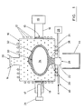
- Figure 1 provides a tunable microwave cavity 10 which has around its exterior a number of water cooling coils 12, and has above it a loading hopper 14.
- a first waveguide 16 is connected at one end to one side of the microwave cavity by a quartz window 15, the other end of the waveguide 16 being coupled to a first microwave source 18.
- a tuning cavity 17 is connected through a second quartz window 19; the tuning cavity being fitted with a fine tuning stub 21.
- exit aperture 20 At the bottom of the cavity 10 there is an exit aperture 20 surrounded by an exit resonant cavity 22 which is coupled by a second wave guide 24 to a second microwave source 26.
- the exit cavity has a discharge aperture 28 in its lower surface.
- a discharge hopper 44 Below the exit aperture 28 is a discharge hopper 44.
- a pipe 40 is connected to one side of the exit cavity 22, so that argon gas can be supplied, as indicated by the arrow A.
- the microwave cavity 10 is initially filled with clean glass frit 30 via the hopper 14 which is continually topped up.
- the cooling water is supplied to the coils 12, and the first microwave source 18 is switched on.
- argon gas is supplied through the pipe 40, and the second microwave source 26 is also switched on.
- an argon plasma at the same region as illustrated in Figure 2 by region 31, is generated and heats the frit on the axis of the cavity 10 as the argon gas permeates upwards. As the heat permeates into the cavity 10 the resistance of the frit / glass decreases.
- the second microwave source 26 and argon gas supply 40 are switched off. Subsequent heating and melting continues by use of the first microwave source 18, the process now being resistive heating.
- the power input is balanced by heat loss from the exterior of the cavity 10 due to cooling.
- the microwave source 18 is then shut off (or reduced in power, and / or the cooling is increased) and the melt is allowed to cool a little so that the ovoid shaped crucible 32 is formed.
- the crucible forms as previously largely molten material is allowed to re-solidify due to the inward retraction of the melted zone.
- the funnel shaped throat / drain hole 38 contains solidified material formed after the plasma torch is turned off.
- the zone / throat 38 consists of a transition zone from unmelted frit, through partially melted frit to material which is effectively part of a soft skull.
- the hopper 14 can be loaded with a material to be processed.
- a material to be processed This may be a high purity glass, or a high melting point glass; alternatively the material to be processed can be a mixture of calcined nuclear waste and glass frit; alternatively, the material to be processed can be a mixture of waste materials and / or glass making materials.
- the plasma torch 31 is used as start up for initial heating, as in preparation of the crucible 32, or for tapping the molten core, then melting continues by use of the first microwave source 18 as before.
- the transition from crucible formation (equipment set up) to processing of materials can be done in a continuous manner. In which case the core will remain molten throughout with the microwave source 18 applied and the feed will change over.
- Volatile waste within the melt is prevented from escaping as it condenses above the melt on the surface of unmelted glass frit in the hopper.
- the contents may be left to mix for 4 to 8 hours.
- the plasma torch When vitrification and / or mixing has proceeded to the required level the plasma torch is reignited in zone 31 to melt a drainage hole in the throat 38. Some of the vitrified nuclear waste is discharged into the discharge hopper 44 and removed to a storage facility. At the same time, more material is added for processing through the top of the crucible. The tapping can then be stopped and this material allowed to mix with the existing material inside the crucible. After a further period of time has elapsed, more vitrified material is discharged into the discharge hopper 44 and material for processing is added through the top of the crucible. The material is processed continuously.
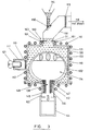
- the apparatus 110 consists of a four sided, top and bottom container. The dimensions are tuned as far as possible to the applied microwave frequency.
- the microwaves are introduced into the cavity through a temperature resistant, non permeable window 115 in waveguide 116 located above the cavity.
- the loading hopper 114 is fitted with a control valve 150 also leading to the waveguide 116.
- the wave guide 116 is fitted with a coarse microwave tuner 160 in the form of sliding shutters 161. The frit enters the apparatus by a gap between the shutters 161.
- the wave guide also contains an optical sensor 163 used to monitor the frit level.
- the layer of unmelted frit particles fed to the apparatus above the skull act as a cold top filter 171 on to which volatile and particulate fumes generated within the melt can be condensed.
- the cavity is provided with a number of external water cooling coils 112 around the periphery of the cavity.
- a fine tuning cavity 117 is connected to the main cavity 134 through a temperature resistant, non permeable alumina window 119, the tuning cavity being fitted with a tuning stub 121.
- the floor of the microwave cavity consists of a removable base plate 148 to allow cleaning of the apparatus. Attached to this plate 148 is an exit chamber 122 also provided with cooling coils 112 on its exterior surface. Within the exit chamber 122 is a metal drain pipe 145 around which is wound an induction heating coil 146. The drain pipe is separated from the base plate by a ceramic insulating piece 147. A raised section of the insulating piece ensures the minimum amount of contact between the metal drain pipe 145 and the base of the cavity, see Figure 4.
- the initial generation of the skull / crucible is achieved in a similar manner to that described for Figure 1.
- the cavity is thus loaded with unmelted glass frit 130, part of which will subsequently form the crucible itself.
- lossy materials which dissipate microwave energy at low temperatures can be introduced.
- lossy material such as graphite rods or blocks are positioned towards the centre of the cavity.
- the microwave source is then switched on and the coarse tuning shutters, and if desired fine tuning stub can be used to tune the filled cavity to the microwave frequency applied.
- the microwaves are absorbed and lead to a very significant heating of the graphite. This heat input, towards the centre of the cavity, is conducted and radiated to the surrounding glass frit and as a consequence leads to melting of it.
- the level of molten glass frit increases and soon direct heating of the frit by the microwaves is attained.
- the graphite absorbs a decreasing proportion of the microwaves under these conditions and eventually melts and is taken up in the material tapped from the cavity at a later point.
- the microwave source 118 is then reduced in power and the melt is allowed to cool so that the ovoid shaped skull 132 is formed.
- the induction heating coil 146 is switched on.
- the coil acts to heat the drain pipe and melt the solidified material within the throat 138 above it.
- the skull 132 is eventually breached and the melt pool 134 is then drained into the discharge flask 144 to the desired extent.
- the induction heating coil 146 is then switched off allowing the lower part of the molten glass to re-solidify ending tapping.
- the hopper 114 is loaded with the material to be processed.
- This may be high purity glass, or a high melting point glass; alternatively the material to be processed can be a mixture of calcined nuclear waste and glass frit; alternatively the material to be processed can be a mixture of waste materials and glass making materials.
- the material is processed or vitrified by heating the skull using the plasma 133 until the top of the skull softens and collapses allowing the material in the hopper to be fed into the skull. Under the action of the microwaves and contact with the molten core this feed material is melted within the skull. The significant convection currents present within the molten core ensure thorough and efficient mixing of the materials.
- Volatile waste within the melt is prevented from escaping as it condenses on the surface of unmelted glass frit in the cold top filter 171.
- the volatiles present will vary depending on the feed materials involved, but in nuclear waste vitrification applications caesium and strontium gas products, amongst others, are encountered.
- a temperature gradient exists between the highest temperature in the molten core 134, through the lower temperature soft skull material and down to still lower temperatures as progression is made away from the skull up the frit feed 171 stacked above the skull.
- Volatiles rising from the melt and seeping through the soft top of the skull will condense as they pass up the temperature gradient and contact the relatively cool frit 171. This frit moves gradually downwards as the processing progresses and carries the volatile material once more back into the melt 134.
- the induction heating coil 146 is switched on to melt the glass plug in the throat 138. A portion of the vitrified waste is drained into the discharge flask 144.
- the skull softens once more and still further of the material to be processed is added through that part of the skull which has softened and collapsed. This material mixes with the already molten contents of the skull. After a period of time, more vitrified waste is removed by the process previously described and more material to be processed is added through the collapsed skull.
- Vitrified material is collected in a discharge flask and removed to a waste storage facility.
- the microwave cavity 10 is 256mm in diameter and 150mm in height
- the first microwave source 18 is a 35kW source operating at 896MHz.
- the second microwave source 26 operates at 2.46GHz.
- the cavity 10 can hold 10-20 kilogrammes of glass, depending on the proportion which is molten, and a 10 kilogramme melt pool can be formed in 45 minutes with a power input of 10kW.
- the peak temperature can be 1,200 degrees C and convection flows of up to 3mm per second may be generated by temperature differentials within the melt, which give effective mixing.
- Re-tuning of the cavity during the formation process for the crucible, or during subsequent processing is possible. Re-tuning is not, however, generally necessary as the cavity once heated, absorbs from microwaves on a broad band basis negating the need for precise tuning. Precise tuning is, however, needed during the initial microwave heating phase as bandwidth absorbency is far lower at this stage requiring closer correspondence between the narrow band of microwaves generated by the magnetron and the narrow band width of microwaves which will be absorbed within the cavity.
- the method and apparatus according to the invention have several advantages, especially for processing of nuclear waste.
- the crucible 32 is not attached to or in contact with the wall of the microwave cavity 10. Because of this the cavity walls are not attacked chemically by the melt or contaminated by radioactivity from the melt.
- the cavity can be cleaned by removing its floor, removing the crucible 32 and the particulate material around it, and breaking up the crucible for recycling through the hopper 14.
- the unmelted and hence, free flowing, characteristics of the unmelted particles making the cleaning process very easy as the material literally falls away from the walls.
- the particles plus voids nature of this material also mean it has a significant insulating effect reducing energy consumption for the process.
- a plasma torch or lossy materials permits easy start-up from cold, and the torch and / or induction heater and / or preferential conduction can be used to burn through the solidified glass sealing the lower throats 38 to permit the ready formation of drainage holes.
- the separation of the crucible from the cavity walls by unmelted material also means that the crucible volume can be controlled and adjusted.
- a smaller crucible can be obtained by decreasing power and / or increasing cooling.
- a larger crucible can be formed by melting a greater portion of the surrounding material.
- a crucible of the desired volume and / or shape can thus be provided without having to alter the overall apparatus dimensions.
- the cold feed above the melt pool and skull serves to filter out and / or remove by condensation any material exiting the top of the melt, such as off gases. This material is fed back into the melt as the process continues so adhering this problem.
Landscapes
- Engineering & Computer Science (AREA)
- Chemical & Material Sciences (AREA)
- General Engineering & Computer Science (AREA)
- Mechanical Engineering (AREA)
- Physics & Mathematics (AREA)
- Materials Engineering (AREA)
- Organic Chemistry (AREA)
- Plasma & Fusion (AREA)
- Electromagnetism (AREA)
- Inorganic Chemistry (AREA)
- High Energy & Nuclear Physics (AREA)
- Furnace Details (AREA)
- Crucibles And Fluidized-Bed Furnaces (AREA)
- Manufacture And Refinement Of Metals (AREA)
- Constitution Of High-Frequency Heating (AREA)
- Glass Melting And Manufacturing (AREA)
- Processing Of Solid Wastes (AREA)
Claims (30)
- Vorrichtung zum Schmelzen von verflüssigbarem Material mit: einem Mikrowellen-Hohlraum (10;110);Mitteln (12;112) zur Kühlung des Äußeren des Hohlraumes;Mitteln (14;114) zur Zuführung des verflüssigbaren Materials, welches zu schmelzen ist, in das Innere des Hohlraumes (10;110);einem Schmelztiegel (32;132) innerhalb des Hohlraumes (10;110) und in Abstand zu dessen Wänden aufgrund einer Schicht ungeschmolzenen Materials (130), wobei der Schmelztiegel von geschmolzenem und rückverfestigtem Material gebildet wird;Mitteln (18) zur Zuführung von Mikrowellen-Energie zum Schmelztiegel (10;110) einer solchen Leistung, daß verflüssigbares Material im Inneren des Schmelztiegels (32;132) geschmolzen wird;und mit Mitteln zur Zuführung von Energie zum Material im Schmelztiegel (10;110) zum Anstechen des geschmolzenen Kernes (34;134) durch Schmelzen des Materials zwischen dem Schmelzkern (34;134) und einer Austrittsöffnung (38) im Hohlraum (10;110).
- Vorrichtung nach Anspruch 1, bei der das zu schmelzende Material ein vorgeformtes Material ist, beispielsweise Glaspartikel, oder bei dem das zu schmelzende Material von schmelzfähigen Materialien umgeben wird, um ein weiteres Material zu bilden, wie beispielsweise glasbildende Materialien.
- Vorrichtung nach Anspruch 1 oder 2, bei dem der Hohlraum Mikrowellen abstimmbar ist.
- Vorrichtung nach einem der vorangehenden Ansprüche, bei der das Material, aus dem der Schmelztiegel (32;132) gebildet wurde, dasselbe Material, wie das ungeschmolzene Material (130) ist.
- Vorrichtung nach einem der vorangehenden Ansprüche, bei der der Schmelztiegel (32;132) auf Abstand von den Wänden, die den Hohlraum (10;110) bilden, durch ungeschmolzenes Material (130) über wenigstens 80 % seines Flächeninhaltes gehalten wird.
- Vorrichtung nach einem der vorangehenden Ansprüche, bei der ungeschmolzenes Material eine bestimmte Form aufweist, mit Lücken zwischen individuellen Partikeln.
- Vorrichtung nach einem der vorangehenden Ansprüche, bei der das Zuführmaterial in den Hohlraum (10;110) mit Hilfe von Mitteln eines Durchganges eingebracht wird und vorzugsweise werden auch die Mikrowellen in den Hohlraum (10;110) mit Mitteln dieses Durchganges (116) eingeführt.
- Vorrichtung nach einem der vorangehenden Ansprüche, bei der eine Säule von Zuführmaterial mit Hilfe des zuströmenden Materials in Gaskontakt mit dem Hohlraum aufrechterhalten wird.
- Vorrichtung nach einem der vorangehenden Ansprüche, bei der zusätzliche Mittel (12;112) vorgesehen sind zur Ergänzung der natürlichen Kühlung des Hohlraumes, wie beispielsweise ein Wärmetauscher.
- Vorrichtung nach einem der vorangehenden Ansprüche, bei der die Kühlmittel eine oder mehrere Röhren (12;112) in Kontakt mit der äußeren Fläche (10;110) aufweisen.
- Vorrichtung nach Anspruch 9 oder 10, bei der der Fluß des Fluids durch den Wärmetauscher (12;112) variabel ist.
- Vorrichtung nach einem der vorangehenden Ansprüche, bei der die Mittel der Zufuhr von Energie zum Schmelzen des Materials/der Partikel innerhalb des Hohlraumes (10;110) zum Anstechen des geschmolzenen Kernes (34;134) weitere Mittel umfassen, wobei diese weiteren Mittel (26;40;146) unterhalb des Hohlraumes positioniert sind.
- Vorrichtung nach Anspruch 12, bei der das weitere Mittel ein Plasma ist und/oder ein Plasmabrenner.
- Vorrichtung nach Anspruch 12, bei der das weitere Mittel eine zweite Mikrowellen-Quelle (26) ist.
- Vorrichtung nach Anspruch 12, bei der das weitere Mittel ein Induktionsheizgerät (146) ist, beispielsweise nach Art einer Funkfrequenz.
- Vorrichtung nach Anspruch 12, bei der die weiteren Mittel Mittel darstellen zum Vorsehen bevorzugt thermischer Leitungen zwischen einem ersten und einem zweiten Ort innerhalb des Hohlraumes (10;110).
- Verfahren zum Vorsehen einer Vorrichtung zum Schmelzen von Material mit:Zuführung eines verflüssigbaren Materials in das Innere eines Mikrowellen-Hohlraumes (10;110);Kühlen des Äußeren des Hohlraumes (10;110);Zuführung von Mikrowellen-Energie zum Hohlraum (10;110) einer solchen Leistung, daß das Material innerhalb des Hohlraumes (10;110) schmilzt, um einen Schmelzkern (34;134) im Abstand zu den Hohlraumwänden (10;110) aufgrund ungeschmolzenen Materiales (130) zu bilden;Bewirkung der Rückverfestigung eines Teiles des geschmolzenen Materials (134) rund um den Schmelzkern;wodurch ein Schmelztiegel (32;132) aus geschmolzenem Material und rückverfestigtem Material innerhalb des Hohlraumes (10;110) gebildet wird, auf Abstand zu seinen Wänden als Boden einer Schicht von ungeschmolzenem Material (130); undder Schmelzkern (34;134) angestochen wird durch Schmelzen des Materials zwischen dem Schmelzkern und einer Austrittsöffnung (28) im Hohlraum (10;110).
- Verfahren nach Anspruch 17, bei dem das Rückverfestigen durch Abschalten der Mikrowellen-Energiezufuhr (18) oder durch Abschwächen der Mikrowellen-Energiezufuhr (18) und/ oder Steigerung der äußeren Kühlung des Hohlraumes(10;110) bewirkt wird.
- Verfahren nach Anspruch 17 oder 18, bei dem es dem Schmelzkern (34;134) erlaubt wird, aus dem Hohlraum (10;110) insbesondere teilweise zu tropfen.
- Verfahren nach Anspruch 17 bis 19, bei dem weiteres zugeführtes Material dank Plasmabildung (133) in der Lücke, die zurückgelassen wird durch das aus dem Hohlraum (10;110) abfließende Material, erhitzt wird.
- Verfahren nach Anspruch 17 bis 20, bei dem das Material durch den Gebrauch eines Plasmabrenners (40) und/oder durch Aufbringen von Mikrowellen-Energie (18) auf in dem Mikrowellen-Hohlraum befindliches loses Material anfänglich erhitzt wird.
- Verfahren nach einem der Ansprüche 17 bis 21, bei dem das Schmelzen des Materials zwischen dem geschmolzenen Kern und der Austrittsöffnung durch das Anwenden eines Plasmabrenners (40) und/oder durch einen Induktionsheizer (146) und/ oder durch bevorzugte Wärmeleitung vom geschmolzenen Kern (34;134) in Richtung auf die Ausgangsöffnung (23) bewirkt wird.
- Verfahren zum Schmelzen von verflüssigbarem Material mit Zufuhr von Partikeln eines Materiales in das Innere eines Mikrowellen-Hohlraumes (10;110), wobei die Materialien einen Schmelztiegel (32;132) beaufschlagen, der von geschmolzenem und rückverfestigtem Material gebildet ist und entfernt ist von den Wänden des Hohlraumes (10;110) durch Schichten von ungeschmolzenem Material (13), bei dem das Material, welches dem Hohlraum (10;110) und dem Schmelztiegel (32;132) zugeführt wird, dort geschmolzen wird, wobei die Energie im Schmelztiegel (32;132) aufgebracht wird in Form von Mikrowellen-Energie und das geschmolzene Material nachfolgend aus dem Schmelztiegel aufgrund des Schmelzens des Materials zwischen dem geschmolzenen Kern und einer Austrittsöffnung (28) in dem Hohlraum abgestochen wird.
- Verfahren nach Anspruch 23, bei dem das verflüssigbare Material vorgesehen wird in einer vorgeformten Form, wie beispielsweise Glaspartikel und/oder hinzugeführt wird als Bestandteil für ein Material, welches gebildet werden soll, z.B. Sand, Natriumkarbonat, Kalk oder Kalziumkarbonat zur Bildung von Glas.
- Verfahren nach Anspruch 23 oder 24, bei dem andere Materialien, die nicht geschmolzen, aber innerhalb der Schmelze verteilt werden sollen, hinzugefügt werden.
- Verfahren nach einem der Ansprüche 23 bis 25, bei dem die Mikrowellen-Energie, die dem Hohlraum aufgegeben wird, abgestimmt wird insbesondere auf das Zentrum des Schmelztiegels.
- Verfahren nach einem der Ansprüche 23 bis 26, bei dem das verflüssigbare Material im Hohlraum unter Schwerkraft-Zuführbedingungen zugeführt wird.
- Verfahren nach einem der Ansprüche 23 bis 27, bei dem das Verfahren das Vorsehen einer weiteren Energieeinspeisung in das zu verflüssigende Material umfaßt mit Mitteln eines Plasmabrenners (40) und/oder durch Mittel eines Induktionsheizgerätes (146) und/oder durch Mittel einer Mikrowelle (26), aufgegeben auf lose Materialien, die in die Kavität eingegeben werden und/oder durch Umgebungsbedingungen.
- Verfahren nach einem der Ansprüche 23 bis 28, bei dem der Plasmabrenner (40) und/oder der Induktionsheizer (146) eingesetzt werden, um anfänglich Energie in den Hohlraum (10; 110) einzubringen, um ein partielles Schmelzen des Materiales zu bewirken.
- Verfahren nach einem der Ansprüche 23 bis 29, bei dem ein Plasmabrenner unter dem Schmelztiegel (32;132) und/oder ein Induktionserhitzer (146) unter dem Schmelztiegel (32;132) und/oder Umgebungswärmeleitung weg von dem geschmolzenen Kern (34;134) in Richtung auf die Anstichöffnung gebraucht werden, um das Material unterhalb des Schmelztiegels zu schmelzen, um so den geschmolzenen Kern anzustechen.
Applications Claiming Priority (3)
| Application Number | Priority Date | Filing Date | Title |
|---|---|---|---|
| GBGB9600895.8A GB9600895D0 (en) | 1996-01-17 | 1996-01-17 | Improved method and apparatus for melting a particulate material |
| GB9600895 | 1996-01-17 | ||
| PCT/GB1997/000119 WO1997026219A1 (en) | 1996-01-17 | 1997-01-16 | Improved method and apparatus for melting a particulate material |
Publications (2)
| Publication Number | Publication Date |
|---|---|
| EP0881992A1 EP0881992A1 (de) | 1998-12-09 |
| EP0881992B1 true EP0881992B1 (de) | 2000-06-07 |
Family
ID=10787130
Family Applications (1)
| Application Number | Title | Priority Date | Filing Date |
|---|---|---|---|
| EP97900366A Expired - Lifetime EP0881992B1 (de) | 1996-01-17 | 1997-01-16 | Verfahren und vorrichtung zum schmelzen von körnformige materialen |
Country Status (9)
| Country | Link |
|---|---|
| US (1) | US6568215B2 (de) |
| EP (1) | EP0881992B1 (de) |
| JP (1) | JP4190581B2 (de) |
| KR (1) | KR19990077310A (de) |
| AU (1) | AU1394597A (de) |
| CA (1) | CA2242893A1 (de) |
| DE (1) | DE69702241T2 (de) |
| GB (1) | GB9600895D0 (de) |
| WO (1) | WO1997026219A1 (de) |
Cited By (1)
| Publication number | Priority date | Publication date | Assignee | Title |
|---|---|---|---|---|
| WO2026052776A1 (de) * | 2024-09-06 | 2026-03-12 | Technische Universität Bergakademie Freiberg, Körperschaft des öffentlichen Rechts | Verwendung, verfahren und vorrichtung zur herstellung und/oder thermischen behandlung von anorganischen rohstoffen und/oder erzeugnissen |
Families Citing this family (23)
| Publication number | Priority date | Publication date | Assignee | Title |
|---|---|---|---|---|
| KR20020021644A (ko) | 1999-06-17 | 2002-03-21 | 우스타브 케미키츠 프로세쥬 아카데미에 베드 케스케 리버블리키 | 유리 재료와 특히 화산 근원의 천연 재료의 열처리 방법및 장치 |
| SE520817C2 (sv) * | 2000-06-16 | 2003-09-02 | Sonny Johansson | Sätt och anordning för smältning av glasmaterial |
| US6693253B2 (en) * | 2001-10-05 | 2004-02-17 | Universite De Sherbrooke | Multi-coil induction plasma torch for solid state power supply |
| FR2867940A1 (fr) * | 2004-02-27 | 2005-09-23 | Richard Caterini | Inertage des dechets domestiques ou industriels par conjugaison de cavites resonnantes et guides d'onde generant la composante preferentielle d'un rayonnement haute frequence |
| US8022341B2 (en) | 2007-05-15 | 2011-09-20 | Appliance Scientific, Inc. | High-speed cooking oven with optimized cooking efficiency |
| US7435931B1 (en) * | 2007-05-15 | 2008-10-14 | Appliance Scientific, Inc. | High-speed cooking oven with optimized cooking efficiency |
| US8134102B2 (en) * | 2007-05-15 | 2012-03-13 | Appliance Scientific, Inc. | High-speed cooking oven with cooking support |
| US8026463B2 (en) * | 2007-05-15 | 2011-09-27 | Appliance Scientific, Inc. | High-speed cooking oven with optimized cooking efficiency |
| US8455797B2 (en) * | 2007-05-15 | 2013-06-04 | Appliance Scientific, Inc. | High-speed cooking oven with optimized cooking efficiency |
| US8129665B2 (en) * | 2007-05-15 | 2012-03-06 | Appliance Scientific, Inc. | Apparatus and method for heating or cooling an object using a fluid |
| DE102008061871B4 (de) * | 2008-12-15 | 2012-10-31 | Heraeus Quarzglas Gmbh & Co. Kg | Schmelztiegel für den Einsatz in einem Tiegelziehverfahren für Quarzglas |
| US20110224474A1 (en) * | 2010-03-09 | 2011-09-15 | Kurion, Inc. | Advanced Microwave System for Treating Radioactive Waste |
| US20110224473A1 (en) * | 2010-03-09 | 2011-09-15 | Kurion, Inc. | Microwave-Enhanced System for Pyrolysis and Vitrification of Radioactive Waste |
| WO2011140258A1 (en) | 2010-05-04 | 2011-11-10 | Appliance Scientific, Inc. | Oven circulating heated air |
| US8759731B2 (en) | 2010-05-06 | 2014-06-24 | Appliance Scientific, Inc. | Plurality of accelerated cooking ovens with master-slave power assembly |
| US10427970B1 (en) | 2016-10-03 | 2019-10-01 | Owens-Brockway Glass Container Inc. | Glass coatings and methods to deposit same |
| US10479717B1 (en) | 2016-10-03 | 2019-11-19 | Owens-Brockway Glass Container Inc. | Glass foam |
| US10364176B1 (en) | 2016-10-03 | 2019-07-30 | Owens-Brockway Glass Container Inc. | Glass precursor gel and methods to treat with microwave energy |
| RU172125U1 (ru) * | 2017-04-05 | 2017-06-29 | Акционерное общество "Лыткаринский завод оптического стекла" | Устройство для разогрева и охлаждения выработочной трубы ванной стекловаренной печи периодического действия |
| JP7615600B2 (ja) * | 2020-10-13 | 2025-01-17 | 日本電気硝子株式会社 | ガラスの製造方法 |
| DE102021112145A1 (de) * | 2021-05-10 | 2022-11-10 | Technische Universität Bergakademie Freiberg | Verfahren zur Herstellung und/oder Verarbeitung von Glas mittels Mikrowellenstrahlung im Einlegebereich |
| DE102022122280A1 (de) * | 2022-09-02 | 2024-03-07 | Technische Universität Bergakademie Freiberg, Körperschaft des öffentlichen Rechts | Kombination elektrischer Heizelemente, enthalten einen Verbundwerkstoff, mit Mikrowellen-Plasmabrennern für Hochtemperaturanwendungen in der Metallurgie, in der chemischen Industrie und in der Zementindustrie |
| WO2025188899A1 (en) * | 2024-03-06 | 2025-09-12 | Inentec Inc. | Selective electromagnetic heating |
Family Cites Families (15)
| Publication number | Priority date | Publication date | Assignee | Title |
|---|---|---|---|---|
| US1684800A (en) * | 1925-12-24 | 1928-09-18 | Maximoff Juvenal | Centrifugal liquid crucible |
| US3151964A (en) * | 1958-06-10 | 1964-10-06 | Glasrock Products | Process of manufacturing fused silica |
| US4052181A (en) * | 1976-02-13 | 1977-10-04 | Nasa | Acoustic energy shaping |
| GB2122859B (en) * | 1982-07-05 | 1985-10-02 | Atomic Energy Authority Uk | Improvements in or relating to microwave heating |
| US4545798A (en) * | 1983-06-02 | 1985-10-08 | Ppg Industries, Inc. | Ablating liquefaction employing plasma |
| FR2566890B1 (fr) * | 1984-06-29 | 1986-11-14 | Commissariat Energie Atomique | Cage froide pour creuset a fusion par induction electromagnetique a frequence elevee |
| US4801435A (en) * | 1986-09-08 | 1989-01-31 | Plasma Holdings N.V. | Hybrid plasma reactor |
| FR2633377B1 (fr) * | 1988-06-27 | 1990-08-31 | Commissariat Energie Atomique | Procede et installation de fusion par micro-ondes d'un materiau corrosif a chaud |
| JPH077102B2 (ja) * | 1988-10-21 | 1995-01-30 | 動力炉・核燃料開発事業団 | 廃棄物処理用溶融炉及びその加熱方法 |
| DE68927849T2 (de) * | 1988-11-17 | 1997-07-24 | Schuller Corp | Verfahren zum Schmelzen von Stoffen |
| GB8911441D0 (en) * | 1989-05-18 | 1989-07-05 | Tetronics Res & Dev Co Ltd | A process for the treatment of molten materials |
| FR2674939B1 (fr) * | 1991-04-03 | 1993-07-30 | Tech Nles Ste Gle | Four de fusion a micro-ondes pour la vitrification de materiaux. |
| FR2708217B1 (fr) * | 1993-07-28 | 1995-10-06 | Europlasma | Procédé d'inertage par torche à plasma de produits contenant des métaux, en particulier des métaux lourds et installation pour sa mise en Óoeuvre. |
| FR2708725B1 (fr) * | 1993-07-29 | 1995-11-10 | Imphy Sa | Procédé de fusion d'un matériau électroconducteur dans un four de fusion par induction en creuset froid et four de fusion pour la mise en Óoeuvre de ce procédé. |
| SE9401065D0 (sv) * | 1993-12-27 | 1994-03-30 | W & E Umwelttechnik Ag | Sätt och anordning för behandling av aska |
-
1996
- 1996-01-17 GB GBGB9600895.8A patent/GB9600895D0/en active Pending
-
1997
- 1997-01-16 CA CA002242893A patent/CA2242893A1/en not_active Abandoned
- 1997-01-16 JP JP52578397A patent/JP4190581B2/ja not_active Expired - Lifetime
- 1997-01-16 KR KR1019980705456A patent/KR19990077310A/ko not_active Withdrawn
- 1997-01-16 DE DE69702241T patent/DE69702241T2/de not_active Expired - Fee Related
- 1997-01-16 WO PCT/GB1997/000119 patent/WO1997026219A1/en not_active Ceased
- 1997-01-16 EP EP97900366A patent/EP0881992B1/de not_active Expired - Lifetime
- 1997-01-16 AU AU13945/97A patent/AU1394597A/en not_active Abandoned
-
2001
- 2001-01-31 US US09/774,493 patent/US6568215B2/en not_active Expired - Fee Related
Cited By (1)
| Publication number | Priority date | Publication date | Assignee | Title |
|---|---|---|---|---|
| WO2026052776A1 (de) * | 2024-09-06 | 2026-03-12 | Technische Universität Bergakademie Freiberg, Körperschaft des öffentlichen Rechts | Verwendung, verfahren und vorrichtung zur herstellung und/oder thermischen behandlung von anorganischen rohstoffen und/oder erzeugnissen |
Also Published As
| Publication number | Publication date |
|---|---|
| DE69702241T2 (de) | 2001-01-25 |
| US6568215B2 (en) | 2003-05-27 |
| CA2242893A1 (en) | 1997-07-24 |
| US20020043082A1 (en) | 2002-04-18 |
| EP0881992A1 (de) | 1998-12-09 |
| KR19990077310A (ko) | 1999-10-25 |
| JP2000503378A (ja) | 2000-03-21 |
| JP4190581B2 (ja) | 2008-12-03 |
| GB9600895D0 (en) | 1996-03-20 |
| WO1997026219A1 (en) | 1997-07-24 |
| AU1394597A (en) | 1997-08-11 |
| DE69702241D1 (de) | 2000-07-13 |
Similar Documents
| Publication | Publication Date | Title |
|---|---|---|
| EP0881992B1 (de) | Verfahren und vorrichtung zum schmelzen von körnformige materialen | |
| CA1212837A (en) | Method of and device for the continuous manufacture of elongate bodies starting from unmolten solid starting material | |
| US4471488A (en) | Direct induction melting device for dielectric substances of the glass or enamel type | |
| US7429239B2 (en) | Methods for melting of materials to be treated | |
| GB2224106A (en) | A melting furnace for treating wastes and a heating method for the same | |
| CA1200826A (en) | Joule melter for the processing of radioactive wastes | |
| JP4563687B2 (ja) | 2つの加熱手段を用いた溶融固化炉及び溶融固化方法 | |
| EP1847156A1 (de) | Vorrichtung zum schnellen start während der innenverglasung von behältern | |
| US20110155720A1 (en) | Directed Energy Melter | |
| JP2547147B2 (ja) | 材料のガラス化及び/又は高密度化のためのマイクロ波融解炉 | |
| CN106287744B (zh) | 熔渣排放装置及等离子炉 | |
| EP0018413B1 (de) | Vorrichtung zum schmelzen mittels mikrowellen | |
| US20060091134A1 (en) | Method and apparatus for heating refractory oxides | |
| JPH0248420A (ja) | 腐食性材料を熱溶融させる方法および設備 | |
| JPH1152095A (ja) | 廃棄物の分離装置および分離方法 | |
| Charvin et al. | Nuclear waste treatment by induction heating and stirring of a metal/glass bath: the PIVIC process | |
| JPS6242974B2 (de) | ||
| JP2004091246A (ja) | 鉄リン酸ガラスの溶融方法 | |
| CA2498404C (en) | Apparatus and method for vitrification of contaminated soil or waste | |
| JPS6056560B2 (ja) | マイクロ波溶融装置 | |
| RU2168226C1 (ru) | Способ остекловывания радиоактивных отходов в охлаждаемом металлическом индукционном плавителе | |
| Shibata et al. | An improved microwave melting furnace for radioactive wastes | |
| KR101951805B1 (ko) | 용탕배출 장치 | |
| HU220470B1 (hu) | Eljárás és berendezés szilárd, elsősorban fémes vagy kerámia anyagoknak elektromos kemencében történő olvasztására | |
| CS200939B1 (cs) | Způsob zatavování radioaktivního odpadu do ekloviny a zařízení k provádění tohoto způsobu |
Legal Events
| Date | Code | Title | Description |
|---|---|---|---|
| PUAI | Public reference made under article 153(3) epc to a published international application that has entered the european phase |
Free format text: ORIGINAL CODE: 0009012 |
|
| 17P | Request for examination filed |
Effective date: 19980930 |
|
| AK | Designated contracting states |
Kind code of ref document: A1 Designated state(s): DE FR GB |
|
| 17Q | First examination report despatched |
Effective date: 19981126 |
|
| GRAG | Despatch of communication of intention to grant |
Free format text: ORIGINAL CODE: EPIDOS AGRA |
|
| GRAG | Despatch of communication of intention to grant |
Free format text: ORIGINAL CODE: EPIDOS AGRA |
|
| GRAG | Despatch of communication of intention to grant |
Free format text: ORIGINAL CODE: EPIDOS AGRA |
|
| GRAH | Despatch of communication of intention to grant a patent |
Free format text: ORIGINAL CODE: EPIDOS IGRA |
|
| GRAH | Despatch of communication of intention to grant a patent |
Free format text: ORIGINAL CODE: EPIDOS IGRA |
|
| GRAA | (expected) grant |
Free format text: ORIGINAL CODE: 0009210 |
|
| AK | Designated contracting states |
Kind code of ref document: B1 Designated state(s): DE FR GB |
|
| REF | Corresponds to: |
Ref document number: 69702241 Country of ref document: DE Date of ref document: 20000713 |
|
| ET | Fr: translation filed | ||
| PGFP | Annual fee paid to national office [announced via postgrant information from national office to epo] |
Ref country code: DE Payment date: 20001219 Year of fee payment: 5 |
|
| PLBE | No opposition filed within time limit |
Free format text: ORIGINAL CODE: 0009261 |
|
| STAA | Information on the status of an ep patent application or granted ep patent |
Free format text: STATUS: NO OPPOSITION FILED WITHIN TIME LIMIT |
|
| 26N | No opposition filed | ||
| REG | Reference to a national code |
Ref country code: GB Ref legal event code: IF02 |
|
| PG25 | Lapsed in a contracting state [announced via postgrant information from national office to epo] |
Ref country code: DE Free format text: LAPSE BECAUSE OF NON-PAYMENT OF DUE FEES Effective date: 20020801 |
|
| REG | Reference to a national code |
Ref country code: GB Ref legal event code: 732E |
|
| REG | Reference to a national code |
Ref country code: FR Ref legal event code: TP |
|
| PGFP | Annual fee paid to national office [announced via postgrant information from national office to epo] |
Ref country code: FR Payment date: 20110630 Year of fee payment: 15 |
|
| PGFP | Annual fee paid to national office [announced via postgrant information from national office to epo] |
Ref country code: GB Payment date: 20110523 Year of fee payment: 15 |
|
| GBPC | Gb: european patent ceased through non-payment of renewal fee |
Effective date: 20120116 |
|
| REG | Reference to a national code |
Ref country code: FR Ref legal event code: ST Effective date: 20120928 |
|
| PG25 | Lapsed in a contracting state [announced via postgrant information from national office to epo] |
Ref country code: GB Free format text: LAPSE BECAUSE OF NON-PAYMENT OF DUE FEES Effective date: 20120116 |
|
| PG25 | Lapsed in a contracting state [announced via postgrant information from national office to epo] |
Ref country code: FR Free format text: LAPSE BECAUSE OF NON-PAYMENT OF DUE FEES Effective date: 20120131 |