EP0882166B1 - Schwimmbecken - Google Patents
Schwimmbecken Download PDFInfo
- Publication number
- EP0882166B1 EP0882166B1 EP97903324A EP97903324A EP0882166B1 EP 0882166 B1 EP0882166 B1 EP 0882166B1 EP 97903324 A EP97903324 A EP 97903324A EP 97903324 A EP97903324 A EP 97903324A EP 0882166 B1 EP0882166 B1 EP 0882166B1
- Authority
- EP
- European Patent Office
- Prior art keywords
- connector
- slip
- hollow
- swimming pool
- pool according
- Prior art date
- Legal status (The legal status is an assumption and is not a legal conclusion. Google has not performed a legal analysis and makes no representation as to the accuracy of the status listed.)
- Expired - Lifetime
Links
- 230000009182 swimming Effects 0.000 title claims abstract description 25
- XLYOFNOQVPJJNP-UHFFFAOYSA-N water Substances O XLYOFNOQVPJJNP-UHFFFAOYSA-N 0.000 claims abstract description 40
- 238000007599 discharging Methods 0.000 claims abstract 2
- 239000011888 foil Substances 0.000 claims description 10
- 229920002994 synthetic fiber Polymers 0.000 claims 2
- 241000238634 Libellulidae Species 0.000 description 15
- 239000004033 plastic Substances 0.000 description 5
- XAGFODPZIPBFFR-UHFFFAOYSA-N aluminium Chemical compound [Al] XAGFODPZIPBFFR-UHFFFAOYSA-N 0.000 description 3
- 229910052782 aluminium Inorganic materials 0.000 description 3
- 229910000831 Steel Inorganic materials 0.000 description 2
- 238000005553 drilling Methods 0.000 description 2
- 239000010959 steel Substances 0.000 description 2
- 238000011161 development Methods 0.000 description 1
- 230000018109 developmental process Effects 0.000 description 1
- 230000000694 effects Effects 0.000 description 1
- 230000008030 elimination Effects 0.000 description 1
- 238000003379 elimination reaction Methods 0.000 description 1
- 238000005516 engineering process Methods 0.000 description 1
- 238000010438 heat treatment Methods 0.000 description 1
- 238000002347 injection Methods 0.000 description 1
- 239000007924 injection Substances 0.000 description 1
- 238000009434 installation Methods 0.000 description 1
- JEIPFZHSYJVQDO-UHFFFAOYSA-N iron(III) oxide Inorganic materials O=[Fe]O[Fe]=O JEIPFZHSYJVQDO-UHFFFAOYSA-N 0.000 description 1
- 238000012986 modification Methods 0.000 description 1
- 230000004048 modification Effects 0.000 description 1
- 210000004197 pelvis Anatomy 0.000 description 1
- 229920001296 polysiloxane Polymers 0.000 description 1
- 238000002360 preparation method Methods 0.000 description 1
- 238000004080 punching Methods 0.000 description 1
- 239000003566 sealing material Substances 0.000 description 1
- 238000000926 separation method Methods 0.000 description 1
- 229920001169 thermoplastic Polymers 0.000 description 1
- 229920001187 thermosetting polymer Polymers 0.000 description 1
- 239000004416 thermosoftening plastic Substances 0.000 description 1
- 230000037303 wrinkles Effects 0.000 description 1
Images



Classifications
-
- E—FIXED CONSTRUCTIONS
- E04—BUILDING
- E04H—BUILDINGS OR LIKE STRUCTURES FOR PARTICULAR PURPOSES; SWIMMING OR SPLASH BATHS OR POOLS; MASTS; FENCING; TENTS OR CANOPIES, IN GENERAL
- E04H4/00—Swimming or splash baths or pools
- E04H4/0018—Easily movable or transportable swimming pools
-
- E—FIXED CONSTRUCTIONS
- E04—BUILDING
- E04H—BUILDINGS OR LIKE STRUCTURES FOR PARTICULAR PURPOSES; SWIMMING OR SPLASH BATHS OR POOLS; MASTS; FENCING; TENTS OR CANOPIES, IN GENERAL
- E04H4/00—Swimming or splash baths or pools
- E04H4/14—Parts, details or accessories not otherwise provided for
- E04H2004/146—Fixing of liners
Definitions
- the invention relates to a swimming pool with a frame and an inner liner that wraps around the top Pool edge placed and by means of the foil and the pool edge a connector designed as a handrail is attached, and with a suction and inflow device for water supply and for water drainage, the connector at least partially itself as Hollow body or is designed to be fastened as a hollow body.
- a connector designed as a handrail is, for example known from WO 92/12310, which consists of individual pieces exists, which each have bores in the end Dowels can be inserted, by means of which two handrail pieces can be attached to each other. The one in question The connector is then pushed onto a pool wall, the one that protrudes down into a lower groove between two Leg is inserted.
- the pools described above have one over the pool edge reaching, closed film, which is attached to the Pool edge is clamped.
- This bracket which is in cross section Is U-shaped and the pool edge with applied The wrapping around the film is at the base of the U-leg on both sides widened out, this widening as a handrail serves.
- the bracket and handrail are made of aluminum or Made of plastic.
- the frame is formed into a closed area Holes drilled, the size of the outer jacket dimensions of the adapted nozzles, skimmers and / or headlights to be installed are.
- further holes are made to the flange-like brackets for the parts mentioned on the outer frame jacket to attach the pelvis.
- the film hung in the pool and the pool up to one Height of about 30 cm flooded with water.
- the aforementioned Accessories flanged with the film, which afterwards is cut out.
- the above-mentioned swimming pool and the type of Flange mounting has several disadvantages: First is drilling of holes in the pelvic mantle according to the number of bores to be manufactured are complex. In addition, the cut edges of the swimming pool created by the holes unprotected because the skimmer is on the outside of the above-ground pool attached and fixed from the inside by means of a flange becomes. The coverage of the cut end faces with silicone or other sealing material often proves to be inadequate, so that the end faces gradually oxidize or rust.
- US 3 793 651 describes a portable swimming pool.
- the swimming pool has one of several segments and posts existing frame, which is lined with a film on the inside is.
- a U-profile cover of a pool edge shows also FR 2 596 445 A3.
- US 5 107 551 shows a profile body, which in a pool wall can be walled in and the groove-shaped Recesses with undercuts to accommodate a has elongated filament.
- the connector is at least partially even as a hollow body or for fastening at least one Hollow body formed, the hollow body or bodies in each case trained for water supply and / or drainage is / are and form a closed hollow chamber system.
- the main idea of the present invention is the connector not only as an upper edge of the Training basin in the form of a handrail, but more integrate necessary parts here.
- the nozzle water inlet and the skimmer water drain through suitable hollow channels, through which the water can flow in and out become.
- electrical power lines can also be integrated for headlights, pumps or the like, the Connector hollow body or a hollow channel created there serves as an empty pipe.
- the connector also as a support for solar cells and their power lines serve.
- the connector is preferably a multi-chamber hollow profile trained, each chamber as a housing or pipe guide has another function.
- the connector is in multiple pitch circles or Part oval pieces made, each essentially let closed pipe systems be created; about desired Pipe continuations are achieved in the cross-sectional profiles two adjacent connectors congruent be formed.
- the connector can be designed as a multi-chamber hollow profile be, each cavity having one of the functions of water supply, Water drainage, electrical cable routing or bracket Fulfills.
- the connector can also in the Sections reaching inside the basin, e.g. over T-shaped Connections have, the end of the sections Skimmer, a water nozzle or a headlight can be arranged can.
- Each section of the connector is with the each adjacent section via a screw, clamp, Snap, snap or other plug connection connected, with what an externally closed hollow chamber system is formed. Any section that forms a hollow body can can be replaced if necessary.
- the modular Structure of the connector can be any pool shape, such as round, square-round, oval, oblong-oval or the like become.
- the connector can also be designed such that tubular via snap, snap or plug connections Hollow bodies are releasably attached, in the simplest case they clicked into place at the bottom of the connector.
- the connector is preferably made of a plastic, especially made of injection molded hard plastic (Thermoplastics) or thermosets.
- the connector have an upper roof surface designed as a seat So designed wider than a handrail.
- the swimming pool can be designed as a above-ground pool his.
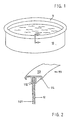
- the above-ground pool according to FIG. 1 consists of a pot-shaped frame that is circular in plan view 10 made of steel or aluminum, one all around the Pool edge attached connector 11 for attaching the Foil or inner lining 12 (see Fig. 2 to 5).
- the film 12 is placed around the upper edge of the pool wall 101 and is attached with a connector 111, the bottom of which has a leg 112 formed in the manner of a clip, to those in the upper part an essentially flat horizontal Handrail roof surface 113 is arranged to the Outside 114 bent ends.
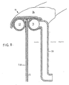
- the configuration of the plug connection 11 according to the invention is 3 and 5, which is uniform that internal cavities are provided as water flow, cable routing, are designed to hold solar cells etc.
- the connector a substantially flat top roof surface 113 which but is designed as a correspondingly wide seat.
- the connector has two below this roof area Hollow chambers 13 and 14, the pipe sections for water supply and -serve serve.
- the cavities 14 can be on their underside Nozzles or other water connections that are equipped lead to underwater nozzles.
- the cavities 13 are with a Skimmer not shown, so connected to scooping water.
- This cavity 15 serves as a heat buffer in the summer avoiding excessive heating of the seat 113 helps because the heat in question is partly from the (colder) water is recorded, which flows through the cavity 14. modifications this embodiment are also possible in such a way that in the Cavity 15 directed nozzles with the relevant cavity 15 Rinse cold water so that it is exposed to strong sunlight the roof surface 113 is cooled accordingly, whereby the seat surface 113 is comfortably tempered.
- FIG. 5 shows a cross section through a multi-chamber hollow profile, which is realized here in an essentially rectangular shape is.
- the hollow chambers 13 and 14 can, as described above, serve as water inlet and outlet, while one of the above Hollow chambers 17 as empty tubes for power cable guides and the remaining space 18 as a space for receiving solar cells (with a correspondingly transparent seat).
- the solar cells arranged in the chamber 18 can supply energy for lamps or headlights, pumps or the like serve.
- the connector 111 designed as a handrail on the underside has two legs 112 forming a bracket. both sides the legs are U-shaped profiles downwards trained in which one of the legs - here leg 116 - is designed as a snap-in receptacle for releasable locking of pipes 19 and 20 as sections of a piping system serve for the water inlet and the water outlet.
- This embodiment has the advantage that the tubular hollow body 19th and 20 can be removed and reinserted if necessary, without having to disconnect the connector 111 from the edge of the pool.
- the two are tubular Hollow body 19 and 20 between the respective leg 112 and a leg 117 arranged parallel thereto inserted, which at the same time an outer closure or a Cover the plastic handrail.
- this handrail is several below the roof surface 113 parallel pipes 118 integrated.
- the water carried here heats up to the roof surface 113 when the sun is shining and can the via a connection system, not shown Circulation can be supplied as hot water.
- Fig. 7 shows a connector in a corresponding embodiment as described in Fig. 3, with an integrated Skimmer and an associated water drain line 22.
- the hollow chamber 13 a side opening with a plug connection for detachable Insert a curved water drain pipe at the end the skimmer 21 is arranged.
- the top forms Outside wall 221 the handrail roof surface.
- the hollow chamber 14 as a water inlet a side opening have the via a plug or snap connection with a Inlet pipe 23 is connected, at the free end of a nozzle is arranged.
- the inlet pipe 23 is in one piece provided with an upper cover profile 24 on both sides of the connector 11 and this across Snap connections is held.
- Fig. 9 shows a plan view of a swimming pool, in which the water leaving a filter 25 via an inlet 26 a nozzle 27 is guided, which is located in the pool Water forms a countercurrent.
- Line 26 the in one of FIGS. 1 to 8 shown in the connector 11 integrated or releasable with this via a clamp connection is connected, is only guided over a semicircle.
- the amount of water supplied via the nozzle 27 an equal amount of water via the skimmer 21 and the connecting line 22 dissipated. Possibly. can be on the inside of the Basin wall 101 still another line or more Lines may be provided.
- the pools When viewed from above, the pools can be round, oval, oblong-oval or also essentially rectangular, but also have any conceivable polygon shapes.
- the connector is made up of individual parts that in sections to a round, oval or one of the aforementioned Forms put together depending on the shape of the pool wall become.
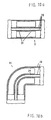
- Two longitudinal cross sections are exemplary in FIGS. 10a and 10b such connector parts 11 shown, at least corresponding to the hollow cross-sectional profile on one side
- the individual elements of the connectors are straight, arc-shaped, part-circular, possibly also S-shaped. After connecting adjacent elements, one becomes closed curve-forming connectors on the pool edge attached.
- the invention also relates to those embodiments in which not all pitch circle segments are constructed identically. It can also be closed depending on the size of the above-ground pool Realize partial circuits that only have a partial arc Add or remove water. The same applies to power cables, Solar cells and their electrical connections to any Consumers.
- Plug connection 11 as a holder for nozzle or nozzle connection pipes, To train headlights, skimmers etc., whereby all parts, preferably via plug or clamp connections flanged or plugged in.
- Plug connection 11 if necessary with the appropriate preparation of the plug connection the above-ground pool design modularly without the jacket-shaped frame to hold and fix swimming pool accessories must be drilled out.
- This has the advantage that the Foil inner lining the frame compared to the filled Water completely without using seals etc. covers.
- the water-bearing arranged on both sides of the clamping groove Channels 13 and 14 also have a correspondingly high weight, what is taking advantage of the residual elasticity of the plastic connector leads to the fact that the groove side walls more closely to the Foil 12 or the pelvic wall 101 are pressed, that is higher clamping pressure is achieved.
- the partial segment-like design of the plug connections allowed also a partial ring exchange, taking out a skimmer or certain nozzles, the separation of headlights etc., without draining the water in the above-ground pool must become.
Landscapes
- Engineering & Computer Science (AREA)
- Architecture (AREA)
- Civil Engineering (AREA)
- Structural Engineering (AREA)
- Devices For Medical Bathing And Washing (AREA)
- Photovoltaic Devices (AREA)
- Lubricants (AREA)
- Massaging Devices (AREA)
- Reciprocating Pumps (AREA)
- Medicines Containing Material From Animals Or Micro-Organisms (AREA)
- Tents Or Canopies (AREA)
- Special Spraying Apparatus (AREA)
- Nozzles (AREA)
Applications Claiming Priority (3)
| Application Number | Priority Date | Filing Date | Title |
|---|---|---|---|
| DE19606496A DE19606496A1 (de) | 1996-02-22 | 1996-02-22 | Ansaug- und Einströmvorrichtung für ein Schwimmbecken |
| DE19606496 | 1996-02-22 | ||
| PCT/EP1997/000781 WO1997031168A1 (de) | 1996-02-22 | 1997-02-10 | Ansaug- und einströmvorrichtung für ein schwimmbecken |
Publications (2)
| Publication Number | Publication Date |
|---|---|
| EP0882166A1 EP0882166A1 (de) | 1998-12-09 |
| EP0882166B1 true EP0882166B1 (de) | 2003-05-02 |
Family
ID=7786034
Family Applications (1)
| Application Number | Title | Priority Date | Filing Date |
|---|---|---|---|
| EP97903324A Expired - Lifetime EP0882166B1 (de) | 1996-02-22 | 1997-02-10 | Schwimmbecken |
Country Status (10)
| Country | Link |
|---|---|
| EP (1) | EP0882166B1 (da) |
| AT (1) | ATE239159T1 (da) |
| CZ (1) | CZ294618B6 (da) |
| DE (2) | DE19606496A1 (da) |
| DK (1) | DK0882166T3 (da) |
| ES (1) | ES2194177T3 (da) |
| HU (1) | HU220122B (da) |
| PL (1) | PL187731B1 (da) |
| PT (1) | PT882166E (da) |
| WO (1) | WO1997031168A1 (da) |
Families Citing this family (4)
| Publication number | Priority date | Publication date | Assignee | Title |
|---|---|---|---|---|
| DE29918542U1 (de) | 1999-10-21 | 2000-02-17 | Wutschik, Mark, 70825 Korntal-Münchingen | Schwimmender Springbrunnen |
| DE10005507A1 (de) * | 2000-02-08 | 2001-08-09 | Rienks Markus | Montagesystem für Behälter-Systeme, insbesondere Schwimmbecken |
| ES1063361Y (es) * | 2006-06-30 | 2007-01-16 | Torrente Ind | Funda para piscinas |
| CN103541563A (zh) * | 2013-10-31 | 2014-01-29 | 镇江汇荣机电科技有限责任公司 | 一种防止幼童溺水游泳池 |
Family Cites Families (5)
| Publication number | Priority date | Publication date | Assignee | Title |
|---|---|---|---|---|
| US3793651A (en) * | 1971-08-23 | 1974-02-26 | Atreo Mfg Co Inc | Portable swimming pool |
| DE2522673A1 (de) * | 1975-05-22 | 1976-12-09 | Whitten Jun | Gitterrost fuer eine schwimmbecken- ueberlaufabflussrinne |
| IT206529Z2 (it) * | 1986-03-26 | 1987-08-10 | A & T Europ Spa | Piscina con bordo sfioratore composito e piano. |
| US5107551A (en) * | 1990-03-23 | 1992-04-28 | Fox Pool Corporation | Multiple accessory swimming pool coping |
| US5161264A (en) * | 1991-01-08 | 1992-11-10 | Gerald Dugas | Above-ground swimming pool |
-
1996
- 1996-02-22 DE DE19606496A patent/DE19606496A1/de not_active Withdrawn
-
1997
- 1997-02-10 CZ CZ19982409A patent/CZ294618B6/cs not_active IP Right Cessation
- 1997-02-10 EP EP97903324A patent/EP0882166B1/de not_active Expired - Lifetime
- 1997-02-10 PT PT97903324T patent/PT882166E/pt unknown
- 1997-02-10 HU HU9900570A patent/HU220122B/hu not_active IP Right Cessation
- 1997-02-10 PL PL97328508A patent/PL187731B1/pl not_active IP Right Cessation
- 1997-02-10 DK DK97903324T patent/DK0882166T3/da active
- 1997-02-10 ES ES97903324T patent/ES2194177T3/es not_active Expired - Lifetime
- 1997-02-10 DE DE59709976T patent/DE59709976D1/de not_active Expired - Fee Related
- 1997-02-10 WO PCT/EP1997/000781 patent/WO1997031168A1/de not_active Ceased
- 1997-02-10 AT AT97903324T patent/ATE239159T1/de not_active IP Right Cessation
Also Published As
| Publication number | Publication date |
|---|---|
| DE19606496A1 (de) | 1997-08-28 |
| HUP9900570A2 (hu) | 1999-06-28 |
| HUP9900570A3 (en) | 1999-11-29 |
| PL187731B1 (pl) | 2004-09-30 |
| ES2194177T3 (es) | 2003-11-16 |
| WO1997031168A1 (de) | 1997-08-28 |
| DK0882166T3 (da) | 2003-08-04 |
| PT882166E (pt) | 2003-09-30 |
| CZ294618B6 (cs) | 2005-02-16 |
| CZ240998A3 (cs) | 1998-12-16 |
| HU220122B (hu) | 2001-11-28 |
| PL328508A1 (en) | 1999-02-01 |
| DE59709976D1 (de) | 2003-06-05 |
| EP0882166A1 (de) | 1998-12-09 |
| ATE239159T1 (de) | 2003-05-15 |
Similar Documents
| Publication | Publication Date | Title |
|---|---|---|
| DE3514053C2 (da) | ||
| EP2385323A2 (de) | Gestell zur Befestigung von Solarmodulen | |
| DE1930274A1 (de) | Kuehlturm | |
| EP0882166B1 (de) | Schwimmbecken | |
| DE3235945C2 (da) | ||
| EP0318536A1 (de) | Fernwärme-übergabevorrichtung. | |
| DE69713082T2 (de) | Filtertreppe für schwimmbassin | |
| DE3148187A1 (de) | Einrichtung zur montage einer wandbatterie | |
| DE2929853A1 (de) | Laermschutzelement | |
| DE20012030U1 (de) | Siphon, insbesondere zur Kondensatableitung aus Heizkesseln o.dgl. Wärmeerzeugung | |
| DE3320619A1 (de) | Filteranlage fuer schwimmbecken | |
| DE2550520B2 (de) | Schwimmbeckenrand für ein mit einer Folie ausgekleidetes Schwimmbecken | |
| EP1128135A2 (de) | Hohler Dachziegel zur Warmwasserbereitung | |
| DE20216270U1 (de) | Versorgungskanal zur Aufnahme von Versorgungsleitungen, insbesondere für Außenanlagen | |
| EP0089466A1 (de) | Tauchbelüfter | |
| EP0557750B1 (de) | Ablaufarmatur einer wandhängenden Toilette | |
| DE10205464A1 (de) | Abzweig- und Absperreinrichtung für Kaltwasserversogungsnetze | |
| DE8209626U1 (de) | Abwassersammel- und hebevorrichtung | |
| DE10211608A1 (de) | Anlage zur Wiederverwertung von gebrauchtem Wasser | |
| DE102005049450B4 (de) | Leuchte | |
| DE10341497B3 (de) | Handlauf für Balkon- und Treppengeländer | |
| DE202005012943U1 (de) | Wannenabtrennung mit integrierter Duschsäule | |
| DE2428581A1 (de) | Massagebrunnen | |
| DE2157604C3 (de) | Halte- und Isoliervorrichtung für Rohrleitungen | |
| DE3124311A1 (de) | "pumpvorrichtung" |
Legal Events
| Date | Code | Title | Description |
|---|---|---|---|
| PUAI | Public reference made under article 153(3) epc to a published international application that has entered the european phase |
Free format text: ORIGINAL CODE: 0009012 |
|
| 17P | Request for examination filed |
Effective date: 19980807 |
|
| AK | Designated contracting states |
Kind code of ref document: A1 Designated state(s): AT BE CH DE DK ES FR GB GR IT LI NL PT SE |
|
| 17Q | First examination report despatched |
Effective date: 20020220 |
|
| RTI1 | Title (correction) |
Free format text: SWIMMING POOL |
|
| GRAH | Despatch of communication of intention to grant a patent |
Free format text: ORIGINAL CODE: EPIDOS IGRA |
|
| RTI1 | Title (correction) |
Free format text: SWIMMING POOL |
|
| GRAH | Despatch of communication of intention to grant a patent |
Free format text: ORIGINAL CODE: EPIDOS IGRA |
|
| GRAA | (expected) grant |
Free format text: ORIGINAL CODE: 0009210 |
|
| AK | Designated contracting states |
Designated state(s): AT BE CH DE DK ES FR GB GR IT LI NL PT SE |
|
| REG | Reference to a national code |
Ref country code: GB Ref legal event code: FG4D Free format text: NOT ENGLISH |
|
| REG | Reference to a national code |
Ref country code: CH Ref legal event code: EP |
|
| REF | Corresponds to: |
Ref document number: 59709976 Country of ref document: DE Date of ref document: 20030605 Kind code of ref document: P |
|
| REG | Reference to a national code |
Ref country code: CH Ref legal event code: NV Representative=s name: INVENTIO AG |
|
| REG | Reference to a national code |
Ref country code: SE Ref legal event code: TRGR |
|
| REG | Reference to a national code |
Ref country code: DK Ref legal event code: T3 |
|
| GBT | Gb: translation of ep patent filed (gb section 77(6)(a)/1977) |
Effective date: 20030714 |
|
| REG | Reference to a national code |
Ref country code: GR Ref legal event code: EP Ref document number: 20030402796 Country of ref document: GR |
|
| REG | Reference to a national code |
Ref country code: PT Ref legal event code: SC4A Free format text: AVAILABILITY OF NATIONAL TRANSLATION Effective date: 20030801 |
|
| ET | Fr: translation filed | ||
| REG | Reference to a national code |
Ref country code: ES Ref legal event code: FG2A Ref document number: 2194177 Country of ref document: ES Kind code of ref document: T3 |
|
| PLBE | No opposition filed within time limit |
Free format text: ORIGINAL CODE: 0009261 |
|
| STAA | Information on the status of an ep patent application or granted ep patent |
Free format text: STATUS: NO OPPOSITION FILED WITHIN TIME LIMIT |
|
| 26N | No opposition filed |
Effective date: 20040203 |
|
| REG | Reference to a national code |
Ref country code: CH Ref legal event code: PCAR Free format text: ISLER & PEDRAZZINI AG;POSTFACH 1772;8027 ZUERICH (CH) |
|
| PGFP | Annual fee paid to national office [announced via postgrant information from national office to epo] |
Ref country code: ES Payment date: 20080228 Year of fee payment: 12 Ref country code: DK Payment date: 20080215 Year of fee payment: 12 |
|
| PGFP | Annual fee paid to national office [announced via postgrant information from national office to epo] |
Ref country code: SE Payment date: 20080214 Year of fee payment: 12 Ref country code: NL Payment date: 20080214 Year of fee payment: 12 |
|
| PGFP | Annual fee paid to national office [announced via postgrant information from national office to epo] |
Ref country code: AT Payment date: 20080215 Year of fee payment: 12 |
|
| PGFP | Annual fee paid to national office [announced via postgrant information from national office to epo] |
Ref country code: BE Payment date: 20080327 Year of fee payment: 12 |
|
| PGFP | Annual fee paid to national office [announced via postgrant information from national office to epo] |
Ref country code: PT Payment date: 20090129 Year of fee payment: 13 Ref country code: DE Payment date: 20081216 Year of fee payment: 13 |
|
| PGFP | Annual fee paid to national office [announced via postgrant information from national office to epo] |
Ref country code: GR Payment date: 20090226 Year of fee payment: 13 Ref country code: GB Payment date: 20090219 Year of fee payment: 13 Ref country code: CH Payment date: 20090217 Year of fee payment: 13 |
|
| BERE | Be: lapsed |
Owner name: *WTS KERESKEDELMI ES SZOLGALTATO KORLATOLT FELELOS Effective date: 20090228 |
|
| PGFP | Annual fee paid to national office [announced via postgrant information from national office to epo] |
Ref country code: IT Payment date: 20090221 Year of fee payment: 13 |
|
| EUG | Se: european patent has lapsed | ||
| REG | Reference to a national code |
Ref country code: DK Ref legal event code: EBP |
|
| PG25 | Lapsed in a contracting state [announced via postgrant information from national office to epo] |
Ref country code: AT Free format text: LAPSE BECAUSE OF NON-PAYMENT OF DUE FEES Effective date: 20090210 |
|
| PGFP | Annual fee paid to national office [announced via postgrant information from national office to epo] |
Ref country code: FR Payment date: 20090213 Year of fee payment: 13 |
|
| NLV4 | Nl: lapsed or anulled due to non-payment of the annual fee |
Effective date: 20090901 |
|
| PG25 | Lapsed in a contracting state [announced via postgrant information from national office to epo] |
Ref country code: NL Free format text: LAPSE BECAUSE OF NON-PAYMENT OF DUE FEES Effective date: 20090901 |
|
| PG25 | Lapsed in a contracting state [announced via postgrant information from national office to epo] |
Ref country code: BE Free format text: LAPSE BECAUSE OF NON-PAYMENT OF DUE FEES Effective date: 20090228 |
|
| REG | Reference to a national code |
Ref country code: ES Ref legal event code: FD2A Effective date: 20090211 |
|
| PG25 | Lapsed in a contracting state [announced via postgrant information from national office to epo] |
Ref country code: ES Free format text: LAPSE BECAUSE OF NON-PAYMENT OF DUE FEES Effective date: 20090211 Ref country code: DK Free format text: LAPSE BECAUSE OF NON-PAYMENT OF DUE FEES Effective date: 20090831 |
|
| REG | Reference to a national code |
Ref country code: PT Ref legal event code: MM4A Free format text: LAPSE DUE TO NON-PAYMENT OF FEES Effective date: 20100810 |
|
| REG | Reference to a national code |
Ref country code: CH Ref legal event code: PL |
|
| GBPC | Gb: european patent ceased through non-payment of renewal fee |
Effective date: 20100210 |
|
| PG25 | Lapsed in a contracting state [announced via postgrant information from national office to epo] |
Ref country code: LI Free format text: LAPSE BECAUSE OF NON-PAYMENT OF DUE FEES Effective date: 20100228 Ref country code: CH Free format text: LAPSE BECAUSE OF NON-PAYMENT OF DUE FEES Effective date: 20100228 |
|
| REG | Reference to a national code |
Ref country code: FR Ref legal event code: ST Effective date: 20101029 |
|
| PG25 | Lapsed in a contracting state [announced via postgrant information from national office to epo] |
Ref country code: PT Free format text: LAPSE BECAUSE OF NON-PAYMENT OF DUE FEES Effective date: 20100810 Ref country code: FR Free format text: LAPSE BECAUSE OF NON-PAYMENT OF DUE FEES Effective date: 20100301 |
|
| PG25 | Lapsed in a contracting state [announced via postgrant information from national office to epo] |
Ref country code: DE Free format text: LAPSE BECAUSE OF NON-PAYMENT OF DUE FEES Effective date: 20100901 |
|
| PG25 | Lapsed in a contracting state [announced via postgrant information from national office to epo] |
Ref country code: GB Free format text: LAPSE BECAUSE OF NON-PAYMENT OF DUE FEES Effective date: 20100210 Ref country code: IT Free format text: LAPSE BECAUSE OF NON-PAYMENT OF DUE FEES Effective date: 20100210 |
|
| PG25 | Lapsed in a contracting state [announced via postgrant information from national office to epo] |
Ref country code: SE Free format text: LAPSE BECAUSE OF NON-PAYMENT OF DUE FEES Effective date: 20090211 |