EP0882176B1 - Abtrennvorrichtung - Google Patents
Abtrennvorrichtung Download PDFInfo
- Publication number
- EP0882176B1 EP0882176B1 EP97904385A EP97904385A EP0882176B1 EP 0882176 B1 EP0882176 B1 EP 0882176B1 EP 97904385 A EP97904385 A EP 97904385A EP 97904385 A EP97904385 A EP 97904385A EP 0882176 B1 EP0882176 B1 EP 0882176B1
- Authority
- EP
- European Patent Office
- Prior art keywords
- centrifuge
- lubricating oil
- filter
- housing
- filter insert
- Prior art date
- Legal status (The legal status is an assumption and is not a legal conclusion. Google has not performed a legal analysis and makes no representation as to the accuracy of the status listed.)
- Expired - Lifetime
Links
- 239000010687 lubricating oil Substances 0.000 claims abstract description 14
- 238000002485 combustion reaction Methods 0.000 claims abstract description 13
- 239000012535 impurity Substances 0.000 claims abstract 2
- 230000001105 regulatory effect Effects 0.000 claims 1
- 239000003921 oil Substances 0.000 abstract description 19
- 238000009423 ventilation Methods 0.000 description 8
- 238000011161 development Methods 0.000 description 5
- 230000018109 developmental process Effects 0.000 description 5
- 239000010779 crude oil Substances 0.000 description 3
- 238000009434 installation Methods 0.000 description 2
- 238000004519 manufacturing process Methods 0.000 description 2
- 238000010276 construction Methods 0.000 description 1
- 239000000356 contaminant Substances 0.000 description 1
- 230000000694 effects Effects 0.000 description 1
- 238000012423 maintenance Methods 0.000 description 1
- 239000003595 mist Substances 0.000 description 1
- 238000007789 sealing Methods 0.000 description 1
Images


Classifications
-
- F—MECHANICAL ENGINEERING; LIGHTING; HEATING; WEAPONS; BLASTING
- F01—MACHINES OR ENGINES IN GENERAL; ENGINE PLANTS IN GENERAL; STEAM ENGINES
- F01M—LUBRICATING OF MACHINES OR ENGINES IN GENERAL; LUBRICATING INTERNAL COMBUSTION ENGINES; CRANKCASE VENTILATING
- F01M11/00—Component parts, details or accessories, not provided for in, or of interest apart from, groups F01M1/00 - F01M9/00
- F01M11/03—Mounting or connecting of lubricant purifying means relative to the machine or engine; Details of lubricant purifying means
-
- B—PERFORMING OPERATIONS; TRANSPORTING
- B01—PHYSICAL OR CHEMICAL PROCESSES OR APPARATUS IN GENERAL
- B01D—SEPARATION
- B01D29/00—Filters with filtering elements stationary during filtration, e.g. pressure or suction filters, not covered by groups B01D24/00 - B01D27/00; Filtering elements therefor
- B01D29/11—Filters with filtering elements stationary during filtration, e.g. pressure or suction filters, not covered by groups B01D24/00 - B01D27/00; Filtering elements therefor with bag, cage, hose, tube, sleeve or like filtering elements
- B01D29/114—Filters with filtering elements stationary during filtration, e.g. pressure or suction filters, not covered by groups B01D24/00 - B01D27/00; Filtering elements therefor with bag, cage, hose, tube, sleeve or like filtering elements arranged for inward flow filtration
-
- B—PERFORMING OPERATIONS; TRANSPORTING
- B01—PHYSICAL OR CHEMICAL PROCESSES OR APPARATUS IN GENERAL
- B01D—SEPARATION
- B01D29/00—Filters with filtering elements stationary during filtration, e.g. pressure or suction filters, not covered by groups B01D24/00 - B01D27/00; Filtering elements therefor
- B01D29/50—Filters with filtering elements stationary during filtration, e.g. pressure or suction filters, not covered by groups B01D24/00 - B01D27/00; Filtering elements therefor with multiple filtering elements, characterised by their mutual disposition
- B01D29/52—Filters with filtering elements stationary during filtration, e.g. pressure or suction filters, not covered by groups B01D24/00 - B01D27/00; Filtering elements therefor with multiple filtering elements, characterised by their mutual disposition in parallel connection
- B01D29/54—Filters with filtering elements stationary during filtration, e.g. pressure or suction filters, not covered by groups B01D24/00 - B01D27/00; Filtering elements therefor with multiple filtering elements, characterised by their mutual disposition in parallel connection arranged concentrically or coaxially
-
- B—PERFORMING OPERATIONS; TRANSPORTING
- B01—PHYSICAL OR CHEMICAL PROCESSES OR APPARATUS IN GENERAL
- B01D—SEPARATION
- B01D29/00—Filters with filtering elements stationary during filtration, e.g. pressure or suction filters, not covered by groups B01D24/00 - B01D27/00; Filtering elements therefor
- B01D29/96—Filters with filtering elements stationary during filtration, e.g. pressure or suction filters, not covered by groups B01D24/00 - B01D27/00; Filtering elements therefor in which the filtering elements are moved between filtering operations; Particular measures for removing or replacing the filtering elements; Transport systems for filters
-
- B—PERFORMING OPERATIONS; TRANSPORTING
- B01—PHYSICAL OR CHEMICAL PROCESSES OR APPARATUS IN GENERAL
- B01D—SEPARATION
- B01D36/00—Filter circuits or combinations of filters with other separating devices
- B01D36/04—Combinations of filters with settling tanks
- B01D36/045—Combination of filters with centrifugal separation devices
-
- B—PERFORMING OPERATIONS; TRANSPORTING
- B04—CENTRIFUGAL APPARATUS OR MACHINES FOR CARRYING-OUT PHYSICAL OR CHEMICAL PROCESSES
- B04B—CENTRIFUGES
- B04B5/00—Other centrifuges
- B04B5/005—Centrifugal separators or filters for fluid circulation systems, e.g. for lubricant oil circulation systems
-
- F—MECHANICAL ENGINEERING; LIGHTING; HEATING; WEAPONS; BLASTING
- F01—MACHINES OR ENGINES IN GENERAL; ENGINE PLANTS IN GENERAL; STEAM ENGINES
- F01M—LUBRICATING OF MACHINES OR ENGINES IN GENERAL; LUBRICATING INTERNAL COMBUSTION ENGINES; CRANKCASE VENTILATING
- F01M1/00—Pressure lubrication
- F01M1/10—Lubricating systems characterised by the provision therein of lubricant venting or purifying means, e.g. of filters
-
- B—PERFORMING OPERATIONS; TRANSPORTING
- B01—PHYSICAL OR CHEMICAL PROCESSES OR APPARATUS IN GENERAL
- B01D—SEPARATION
- B01D2201/00—Details relating to filtering apparatus
- B01D2201/08—Regeneration of the filter
- B01D2201/081—Regeneration of the filter using nozzles or suction devices
- B01D2201/082—Suction devices placed on the cake side of the filtering element
-
- B—PERFORMING OPERATIONS; TRANSPORTING
- B01—PHYSICAL OR CHEMICAL PROCESSES OR APPARATUS IN GENERAL
- B01D—SEPARATION
- B01D2201/00—Details relating to filtering apparatus
- B01D2201/29—Filter cartridge constructions
- B01D2201/291—End caps
-
- B—PERFORMING OPERATIONS; TRANSPORTING
- B01—PHYSICAL OR CHEMICAL PROCESSES OR APPARATUS IN GENERAL
- B01D—SEPARATION
- B01D2201/00—Details relating to filtering apparatus
- B01D2201/30—Filter housing constructions
- B01D2201/301—Details of removable closures, lids, caps, filter heads
- B01D2201/305—Snap, latch or clip connecting means
-
- B—PERFORMING OPERATIONS; TRANSPORTING
- B01—PHYSICAL OR CHEMICAL PROCESSES OR APPARATUS IN GENERAL
- B01D—SEPARATION
- B01D2201/00—Details relating to filtering apparatus
- B01D2201/34—Seals or gaskets for filtering elements
-
- B—PERFORMING OPERATIONS; TRANSPORTING
- B01—PHYSICAL OR CHEMICAL PROCESSES OR APPARATUS IN GENERAL
- B01D—SEPARATION
- B01D2201/00—Details relating to filtering apparatus
- B01D2201/40—Special measures for connecting different parts of the filter
- B01D2201/4084—Snap or Seeger ring connecting means
-
- F—MECHANICAL ENGINEERING; LIGHTING; HEATING; WEAPONS; BLASTING
- F01—MACHINES OR ENGINES IN GENERAL; ENGINE PLANTS IN GENERAL; STEAM ENGINES
- F01M—LUBRICATING OF MACHINES OR ENGINES IN GENERAL; LUBRICATING INTERNAL COMBUSTION ENGINES; CRANKCASE VENTILATING
- F01M1/00—Pressure lubrication
- F01M1/16—Controlling lubricant pressure or quantity
-
- F—MECHANICAL ENGINEERING; LIGHTING; HEATING; WEAPONS; BLASTING
- F01—MACHINES OR ENGINES IN GENERAL; ENGINE PLANTS IN GENERAL; STEAM ENGINES
- F01M—LUBRICATING OF MACHINES OR ENGINES IN GENERAL; LUBRICATING INTERNAL COMBUSTION ENGINES; CRANKCASE VENTILATING
- F01M13/00—Crankcase ventilating or breathing
- F01M13/02—Crankcase ventilating or breathing by means of additional source of positive or negative pressure
- F01M13/021—Crankcase ventilating or breathing by means of additional source of positive or negative pressure of negative pressure
- F01M13/022—Crankcase ventilating or breathing by means of additional source of positive or negative pressure of negative pressure using engine inlet suction
- F01M13/023—Control valves in suction conduit
Definitions
- the invention relates to a device for separating contaminants from the lubricating oil of an internal combustion engine.
- Such devices are known, for example in DE-PS 43 06 431. If you want such devices, for example in tight-fitting engine compartments use of internal combustion engines, it is disadvantageous that for such a device often lacks the space required.
- the object of the invention is therefore a device for oil management to create an internal combustion engine which is inexpensive to manufacture, reliable in operation and easy to maintain.
- This task is accomplished by the Features of claim 1 solved. According to the task solved in that the filter insert and the centrifuge in side by side arranged housings are located. This makes it compact Design achieved.
- the two housings arranged side by side are one Component summarized, which has a common housing area. This makes this housing easy to manufacture. The one for care necessary channels are integrated in the component. This will also Construction space saved.
- crankcase ventilation valve is placed under the centrifuge. This is by means of a connection opening connected to the crankcase of the internal combustion engine.
- the crankcase ventilation valve can also save space in the arrangement can be integrated since an additional valve housing is not required.
- a pressure control valve is included in at least one of the housings connecting lubricating oil channels. This ensures that, for example, optimal working conditions in the centrifuge to rule.
- centrifuge and / or the filter insert in the area of a functional element of the internal combustion engine are arranged. This guarantees that so-called functional units can be formed to
- Example of accessing control, regulation or drive elements together can. This applies equally to jointly usable housing walls.
- the centrifuge and / or the filter insert and the Functional element has at least one common housing side.
- the spatial dimensions can be also reduce.
- the filter at open filter housing is removable or replaceable. This makes maintenance easier or the exchange of the elements.
- the supply channel Device corresponds to the feed channel of the centrifuge.
- the Centrifuge operated on the crude oil side.
- the Discharge channel of the device corresponds to the feed channel of the centrifuge.
- the centrifuge is operated on the pure oil side.
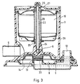
- the device 1 which is shown in FIGS. 1 and 2, consists of a filter insert 2, which can be seen in FIGS. 1, 4a and 4b, and a centrifuge rotor 10 shown in FIG. 3, which, as shown in FIG. 1, are connected by means of a communicating lubricating oil channel 6.
- the device 1 is fastened to the internal combustion engine by means of housing fastening bores 17 shown in FIGS. 1 and 2 and screws (not shown in more detail). Both the filter insert 2 and the centrifuge rotor 10 are located in separate housings.
- the housing 11 of the filter insert 2, which is shown in FIGS. 1, 2, 4a and 4b, has a feed channel 4 shown in FIGS.
- FIG. 3 also shows how the oil entering the centrifuge rotor 0 is guided through a hollow centrifuge axis 24, the centrifuge axis 24 being anchored in the centrifuge housing 3 and the centrifuge housing cover 21 in such a way that in connection with the sealing centrifuge bearing 25, the oil is merely over the centrifuge rotor nozzles 26 can get into the space of the centrifuge housing 3 surrounding the centrifuge rotor. From there, the filtered and centrifuged oil leaves the device 1 via the discharge channel 5, which is located on the housing of the centrifuge 3 and is shown in FIGS. 1, 2, 3, 4a, 4b, 6a and 6b, without pressure.
- the arrangement of the centrifuge housing 3 takes place on the internal combustion engine in the manner shown in FIG.
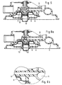
- crankcase ventilation valve 8 has the one coil spring 13 communicating with a valve plate 23, which is also visible in FIGS. 5 and 6a, and via which 2, 3, 5 and 6a is vented, and the centrifuge housing 3 has a common housing wall 9, which can also be seen in FIGS. 5 and 6a.
- the centrifuge housing 3 is fastened to the device 1 by means of the centrifuge housing fastenings 20 shown in FIGS. 1 and 2. Both the housing 11 of the filter insert 2 and that of the centrifuge 3 are to be opened (FIGS.
- FIG. 4b has two filter inserts 2, which are accommodated in a housing in such a way that they can be replaced after the housing has been opened.
- the filter inserts 2 are in the installed state by means of the filter seal 19 shown in FIGS. 4a and 4b Filter space emptying opening 18, which is shown in Figure 2, sealed. If the filter inserts 2 are replaced, the oil in the filter chamber can flow into the crankcase without pressure.
- the filter inserts 2 have, as shown in FIGS. 4a and 4b, filter bypass valves 15 which, when the filter is added, do not allow the oil pressure to drop.
- the centrifuge is loaded on the crude oil side, as shown in FIG. 6a. The loading of the centrifuge on the pure oil side shown in comparison can be seen in FIG. 6b. In the embodiments described above, the centrifuge is operated in the bypass flow, the oil is discharged from the centrifuge without pressure, and the centrifuged oil flows, for example, into the oil pan (not shown in more detail).
Landscapes
- Engineering & Computer Science (AREA)
- Chemical & Material Sciences (AREA)
- Chemical Kinetics & Catalysis (AREA)
- Mechanical Engineering (AREA)
- General Engineering & Computer Science (AREA)
- Lubrication Details And Ventilation Of Internal Combustion Engines (AREA)
- Centrifugal Separators (AREA)
Abstract
Description
- Figur 1
- eine Draufsicht der Vorrichtung,
- Figur 2
- eine Ansicht von unten,
- Figur 3
- einen Schnitt entlang der Linie C-C,
- Figur 4a, b
- einen Schnitt entlang der Linie A-A,
- Figur 5
- einen Schnitt entlang der Linie C-E,
- Figur 6a, b
- einen Schnitt entlang der Linie C-E.
Die Anordnung des Zentrifugengehäuses 3 erfolgt an der Verbrennungskraftmaschine in der Weise, wie die in Figur 3 dargestellt wird, daß das Kurbelgehäusentlüftungsventil 8 das eine mit einer Ventilplatte 23 kommunizierende Schraubenfeder 13, die ebenfalls in den Figuren 5 und 6a sichtbar ist, aufweist und über den in den Figuren 2, 3, 5 und 6a gezeigten Entlüftungskanal 12 entlüftet wird, und das Zentrifugengehäuse 3 eine gemeinsame Gehäusewandung 9, die zusätzlich in den Figuren5 und 6a zu sehen ist, aufweisen. Das Kurbelgehäuseentlüftungsventil 8, das zusätzlich in den Figuren 5, 6a und 6b gezeigt wird, hat mittels Verbindungsöffnung 14, die in Figur 3 erscheint, Kontakt zum nicht näher dargestellten Kurbelgehäuse der Verbrennungskraftmaschine. Das Zentrifugengehäuse 3 ist mittels der in Fig. 1 und Fig. 2 dargestellten Zentrifugengehäusebefestigungen 20 an der Vorrichtung 1 befestigt.
Sowohl das Gehäuse 11 von Filtereinsatz 2 als auch das von Zentrifuge 3 sind zu öffnen (Fig. 3,4), so, daß nachdem sowohl der in den Figuren 4a und 4b dargestellten Filtergehäusedeckel 16 als auch der Zentrifugengehäusedeckel 21 abgenommen sind, bei geöffneten Gehäusen Filtereinsatz 2 oder Zentifugenrotor 10 herausnehmbar bzw. auswechselbar sind. Die Gehäusedeckel 16, 21 sind mittels Schraub- oder Schnappverbindung mit den Gehäusen derart verbunden, daß im Betriebszustand kein Öl das Gehäuseinnere verlassen kann, wie z. B. in Fig. 4a durch Dichtung 27 dargestellt.
Im mit den Gehäusen des Filtereinsatzes 2 und der Zentrifuge 3 kommunizierenden Schmierölkanal 6 befindet sich ein Druckregelventil 7, das in Figur 5 dargestellt ist und als Kugel-Feder-Ventil ausgeführt ist.
In einer alternativen Ausgestaltung weist die Vorrichtung 1, wie in Fig. 4b dargestellt, zwei Filtereinsätze 2 auf, die in einem Gehäuse so untergebracht sind, daß sie nach dem Öffnen des Gehäuses ausgewechselt werden können. Die Filtereinsätze 2 sind im eingebauten Zustand mittels der in den Figuren 4a und 4b dargestellten Filterabdichtung 19 zur
Filterraumentleerungsöffnung 18, die in Figur 2 gezeigt wird, hin abgedichtet. Im Falle der Auswechslung der Filtereinsätze 2 kann das im Filterraum vorhandene Öl drucklos in das Kurbelgehäuse abfließen. Die Filtereinsätze 2 weisen, wie in den Figuren 4a und 4b dargestellt, Filter-Umgehungsventile 15 auf, die bei zugesetztem Filter den Öldruck nicht abreißen lassen.
In einer weiteren alternativen Ausgestaltung wird die Zentrifuge rohölseitig beaufschlagt, wie dies in Figur 6a dargestellt wird. Die im Vergleich dazu dargestellte reinölseitige Beaufschlagung der Zentrifuge ist Figur 6b zu entnehmen. In den vorstehend geschilderten Ausgestaltungen wird die Zentrifuge im Nebenstrom betrieben, der Ölablauf aus der Zentrifuge erfolgt drucklos, das zentrifugierte Öl fließt beispielsweise in die nicht näher dargestellte Ölwanne.
- 1
- Vorrichtung
- 2
- Filtereinsatz
- 3
- Zentrifugengehäuse
- 4
- Zuleitungskanal
- 5
- Ableitungskanal
- 6
- kommunizierender Schmierölkanal
- 7
- Druckregelventil
- 8
- Kurbegehäuseentlüftungsventil
- 9
- gemeinsame Gehäusewandung
- 10
- Zentrifugenrotor
- 11
- Gehäuse des Filtereinsatzes
- 12
- Entlüftungskanal
- 13
- Schraubenfeder
- 14
- Verbindungsöffnung
- 15
- Filter-Umgehungsventil
- 16
- Filtergehäusedeckel
- 17
- Gehäusebefestigungsbohrung
- 18
- Filterraumentleerungsöffnung
- 19
- Filterabdichtung
- 20
- Zentrifugengehäusebefestigung
- 21
- Zentrifugengehäusedeckel
- 22
- Zulauf
- 23
- Ventilplatte
- 24
- Zentrifugenachse
- 25
- Zentrifugenlagerung
- 26
- Zentrifugenrotordüse
- 27
- Dichtung
- 28
- Zulauföffnung im Zentrifugenrotor
Claims (7)
- Vorrichtung zum Abtrennen von Verunreinigungen aus dem Schmieröl einer Verbrennungskraftmaschine, wobei die Vorrichtung (1) wenigstens einen Filtereinsatz (2), eine mittels durchströmenden Schmieröls antreibbare Zentrifuge und mindestens einen Zuleitungskanal (4) für zu reinigendes Schmieröl und mindestens einen Ableitungskanal (5) für gereinigtes Schmieröl aufweist, wobei der Filtereinsatz (2) und die mittels durchströmendem Schmieröl antreibbare Zentrifuge in separaten, wenigstens mittels einem kommunizierenden Schmierölkanal (6) verbundenen, nebeneinander angeordneten Gehäusen befindlich sind, deren Mittelachsen parallel verlaufen, dadurch gekennzeichnet, daß ein Kurbelgehäuseentlüftungsventil (8) unter der Zentrifuge mit einer gemeinsamen Gehäusewandung untergebracht ist, wobei das Kurbelgehäuseentlüftungsventil (8) mittels einer Verbindungsöffnung mit dem Kurbelgehäuse der Verbrennungskraftmaschine kommuniziert.
- Vorrichtung nach Anspruch 1, dadurch gekennzeichnet, daß in wenigstens einem des die Gehäuse verbindenden Schmierölkanäle ein Druckregelventil (7) enthalten ist.
- Vorrichtung nach einem oder mehreren der vorgenannten Ansprüche, dadurch gekennzeichnet, daß die Zentrifuge und/oder der Filtereinsatz (2) im Bereich eines Funktionselements der Brennkraftmaschine angeordnet sind.
- Vorrichtung nach einem oder mehreren der vorgenannten Ansprüche, dadurch gekennzeichnet, daß der Filtereinsatz (2) bei geöffnetem Filtergehäuse herausnehmbar bzw. auswechselbar ist.
- Vorrichtung nach einem oder mehreren der vorgenannten Ansprüche, dadurch gekennzeichnet, daß der Zentrifugenrotor (10) der Zentrifuge bei geöffnetem Zentrifugengehäuse(3) herausnehmbar bzw. auswechselbar ist.
- Vorrichtung nach einem oder mehreren der vorgenannten Ansprüche, dadurch gekennzeichnet, daß der Zuleitungskanal der Vorrichtung (1) dem Zuleitungskanal (4) der Zentrifuge entspricht.
- Vorrichtung nach einem oder mehreren der vorgenannten Ansprüche, dadurch gekennzeichnet, daß der Zuleitungskanal der Vorrichtung (1) dem Zuleitungskanal (4) des Filters (2) entspricht.
Applications Claiming Priority (3)
| Application Number | Priority Date | Filing Date | Title |
|---|---|---|---|
| DE19606182 | 1996-02-20 | ||
| DE19606182A DE19606182A1 (de) | 1996-02-20 | 1996-02-20 | Abtrennvorrichtung |
| PCT/EP1997/000537 WO1997031180A1 (de) | 1996-02-20 | 1997-02-06 | Abtrennvorrichtung |
Publications (2)
| Publication Number | Publication Date |
|---|---|
| EP0882176A1 EP0882176A1 (de) | 1998-12-09 |
| EP0882176B1 true EP0882176B1 (de) | 2000-08-23 |
Family
ID=7785845
Family Applications (1)
| Application Number | Title | Priority Date | Filing Date |
|---|---|---|---|
| EP97904385A Expired - Lifetime EP0882176B1 (de) | 1996-02-20 | 1997-02-06 | Abtrennvorrichtung |
Country Status (9)
| Country | Link |
|---|---|
| US (1) | US6058899A (de) |
| EP (1) | EP0882176B1 (de) |
| JP (1) | JP2000504808A (de) |
| KR (1) | KR19990082663A (de) |
| BR (1) | BR9707653A (de) |
| CA (1) | CA2247183A1 (de) |
| DE (2) | DE19606182A1 (de) |
| WO (1) | WO1997031180A1 (de) |
| ZA (1) | ZA971420B (de) |
Families Citing this family (27)
| Publication number | Priority date | Publication date | Assignee | Title |
|---|---|---|---|---|
| GB2317203B (en) * | 1996-09-13 | 2000-03-08 | Glacier Metal Co Ltd | I C engine crankcase breather assembly |
| DE19736039B4 (de) * | 1997-08-20 | 2018-01-11 | Man Truck & Bus Ag | Brennkraftmaschine mit einem Ölmodul |
| FR2772636B1 (fr) * | 1997-12-19 | 2000-07-21 | Alfa Laval Moatti Snc | Ensemble pour l'epuration automatique d'un fluide pollue et procede de mise en oeuvre |
| DE19806929A1 (de) * | 1998-02-19 | 1999-08-26 | Knecht Filterwerke Gmbh | Dichteinrichtung für ein Ringfilter in einem Filtergehäuse |
| SE513440C2 (sv) * | 1999-01-27 | 2000-09-11 | Alfa Laval Ab | Utlopp vid centrifugalseparator med reaktionsdriven rotor |
| DE19907267B4 (de) * | 1999-02-20 | 2005-08-04 | Mtu Friedrichshafen Gmbh | Kühlermodul für eine Brennkraftmaschine |
| DE20018278U1 (de) * | 2000-10-25 | 2002-02-28 | Ing. Walter Hengst GmbH & Co. KG, 48147 Münster | Aggregatemodul einer Brennkraftmaschine |
| US6364822B1 (en) * | 2000-12-07 | 2002-04-02 | Fleetguard, Inc. | Hero-turbine centrifuge with drainage enhancing baffle devices |
| DE10148405A1 (de) * | 2001-10-01 | 2003-04-10 | Otto Altmann | Doppelwand-Zyklon-System als Abtrennvorrichtung |
| DE20310841U1 (de) * | 2003-07-14 | 2004-11-25 | Hengst Gmbh & Co.Kg | Modul für eine Brennkraftmaschine |
| US8215492B2 (en) * | 2003-09-18 | 2012-07-10 | Pur Water Purification Products, Inc. | Water treatment devices and cartridges therefor |
| DE10350562B4 (de) * | 2003-10-29 | 2008-07-31 | Daimler Ag | Vorrichtung zur Aufbereitung von Schmieröl |
| DE102004037414A1 (de) * | 2004-07-30 | 2006-03-23 | Mann + Hummel Gmbh | Zentrifugalabscheider |
| DE202005014232U1 (de) * | 2005-09-08 | 2007-02-01 | Hengst Gmbh & Co.Kg | Zentrifugen, insbesondere für das Schmieröl einer Brennkraftmaschine |
| DE202006011992U1 (de) * | 2006-08-03 | 2007-12-20 | Mann + Hummel Gmbh | Gehäuse für eine Kurbelgehäuseentlüftungsvorrichtung |
| DE202007014822U1 (de) * | 2007-10-02 | 2009-02-19 | Mann+Hummel Gmbh | Filterelement Zackendichtung |
| US8157997B2 (en) | 2007-10-17 | 2012-04-17 | Caterpillar Inc. | Canister filter system with drain that cooperates with filter element |
| US8501003B2 (en) | 2007-10-17 | 2013-08-06 | Caterpillar Inc. | Canister filter system with drain that cooperates with filter element |
| US8419938B2 (en) * | 2007-11-19 | 2013-04-16 | Catepillar Inc. | Fluid filter system |
| US8272516B2 (en) | 2007-11-19 | 2012-09-25 | Caterpillar Inc. | Fluid filter system |
| DE102008046499A1 (de) * | 2008-09-09 | 2010-03-18 | Mann + Hummel Gmbh | Filter mit Drainageanschluss |
| USD646750S1 (en) | 2010-10-01 | 2011-10-11 | Caterpillar Inc. | Fuel filter |
| USD646350S1 (en) | 2010-10-01 | 2011-10-04 | Caterpillar Inc. | Filter |
| USD648822S1 (en) | 2010-10-01 | 2011-11-15 | Caterpillar Inc. | Fuel filter |
| WO2018061085A1 (ja) * | 2016-09-27 | 2018-04-05 | 本田技研工業株式会社 | 内燃機関の潤滑構造 |
| JP6452742B2 (ja) * | 2017-03-07 | 2019-01-16 | 本田技研工業株式会社 | 内燃機関のオイルフィルタ構造 |
| CN116871066A (zh) * | 2023-06-27 | 2023-10-13 | 青岛洛克环保科技有限公司 | 基于生物技术用活性淤泥分散式筛选设备及其筛选方法 |
Family Cites Families (14)
| Publication number | Priority date | Publication date | Assignee | Title |
|---|---|---|---|---|
| US3125083A (en) * | 1964-03-17 | Device for preventing contamination of crank case oil | ||
| DE1166155B (de) * | 1958-12-11 | 1964-03-26 | Mann & Hummel Filter | Mehrstufige Reinigungsvorrichtung fuer im Kreislauf gefuehrte Fluessigkeiten, insbesondere Schmieroel |
| DE2905645A1 (de) * | 1979-02-14 | 1980-08-28 | Glacier Metal Co Ltd | Zentrifugalseparator |
| US4324213A (en) * | 1980-01-21 | 1982-04-13 | Cummins Engine Company, Inc. | Lubrication fluid filtering and cooling assembly |
| GB2160796B (en) * | 1984-05-04 | 1987-09-16 | Ae Plc | Oil cleaning assemblies for engines |
| GB2160449B (en) * | 1984-05-04 | 1988-09-21 | Ae Plc | Oil cleaning assemblies for engines |
| JP2886190B2 (ja) * | 1989-08-04 | 1999-04-26 | 阪神内燃機工業株式会社 | 油清浄装置 |
| DE4403425A1 (de) * | 1993-02-20 | 1994-08-25 | Audi Ag | Verfahren und Vorrichtung zur Überwachung der Funktion einer Freistrahl-Zentrifuge in Druckumlauf-Schmiersystem |
| DE4306431C2 (de) * | 1993-03-02 | 2000-04-20 | Hengst Walter Gmbh & Co Kg | Vorrichtung zum Abtrennen von Verunreinigungen aus dem Schmieröl einer Brennkraftmaschine |
| DE4311906A1 (de) * | 1993-04-10 | 1994-10-13 | Audi Ag | Vorrichtung zum Entlüften des Kurbelgehäuses einer Brennkraftmaschine |
| DE4420868C2 (de) * | 1994-06-15 | 1997-01-23 | Knecht Filterwerke Gmbh | Vorrichtung zum Reinigen von Schmieröl |
| DE4430751A1 (de) * | 1994-08-30 | 1996-03-07 | Mann & Hummel Filter | Fluidkreislauf mit einem Hauptstromfilter |
| GB2298037B (en) * | 1995-02-18 | 1999-07-28 | Glacier Metal Co Ltd | Temperature regulating liquid conditioning arrangements |
| DE29518840U1 (de) * | 1995-11-28 | 1996-01-18 | eco clean systems Filtriertechnik GmbH, 21079 Hamburg | Mobile Anlage zum Reinigen von verunreinigten Flüssigkeiten |
-
1996
- 1996-02-20 DE DE19606182A patent/DE19606182A1/de not_active Withdrawn
-
1997
- 1997-02-06 KR KR1019980706408A patent/KR19990082663A/ko not_active Withdrawn
- 1997-02-06 JP JP9529742A patent/JP2000504808A/ja active Pending
- 1997-02-06 DE DE59702237T patent/DE59702237D1/de not_active Expired - Fee Related
- 1997-02-06 WO PCT/EP1997/000537 patent/WO1997031180A1/de not_active Ceased
- 1997-02-06 US US09/125,507 patent/US6058899A/en not_active Expired - Lifetime
- 1997-02-06 CA CA002247183A patent/CA2247183A1/en not_active Abandoned
- 1997-02-06 EP EP97904385A patent/EP0882176B1/de not_active Expired - Lifetime
- 1997-02-06 BR BR9707653A patent/BR9707653A/pt not_active Application Discontinuation
- 1997-02-19 ZA ZA9701420A patent/ZA971420B/xx unknown
Also Published As
| Publication number | Publication date |
|---|---|
| EP0882176A1 (de) | 1998-12-09 |
| WO1997031180A1 (de) | 1997-08-28 |
| US6058899A (en) | 2000-05-09 |
| JP2000504808A (ja) | 2000-04-18 |
| CA2247183A1 (en) | 1997-08-28 |
| DE59702237D1 (de) | 2000-09-28 |
| ZA971420B (en) | 1997-08-27 |
| DE19606182A1 (de) | 1997-08-21 |
| BR9707653A (pt) | 1999-07-27 |
| KR19990082663A (ko) | 1999-11-25 |
Similar Documents
| Publication | Publication Date | Title |
|---|---|---|
| EP0882176B1 (de) | Abtrennvorrichtung | |
| DE3713210C2 (de) | ||
| EP1174597A1 (de) | Baugruppe für eine Brennkraftmaschine mit einem Ölfilter | |
| DE4428771A1 (de) | Filter, insbesondere zum Reinigen von Schmieröl einer Brennkraftmaschine | |
| DE4427753A1 (de) | Ölabscheider | |
| EP1644124A1 (de) | Einrichtung zum schalten von zyklonen | |
| DE3341359A1 (de) | Brennkraftmaschine mit durchgaengen fuer durchgeblasenes gas oder gemisch | |
| EP0925428A1 (de) | Baugruppe für eine verbrennungskraftmaschine | |
| DE19701977B4 (de) | Brennkraftmaschine mit einem Ventilkammerdeckel | |
| EP1246680A1 (de) | Filtervorrichtung | |
| EP0024514B1 (de) | Filteranordnung zum Filtern von Flüssigkeiten, insbesondere Motoröl | |
| EP1284342B1 (de) | Ölauffangvorrichtung für eine Brennkraftmaschine, insbesondere für einen Boxermotor | |
| EP1310637B1 (de) | Brennkraftmaschine mit mindestens zwei Zylinderbankreihen | |
| DE19711457A1 (de) | Ölfilter mit zwei Ölströmen in einem gemeinsamen Gehäuse | |
| DE19701066B4 (de) | Vorrichtung zum Filtrieren von Öl | |
| EP1337308B1 (de) | Aggregatemodul einer brennkraftmaschine | |
| DE102005006438A1 (de) | Einrichtung zur Entlüftung eines Kurbelgehäuses einer Brennkraftmaschine sowie Brennkraftmaschine mit insbesondere V-förmiger Anordnung der Zylinder | |
| DE19736039B4 (de) | Brennkraftmaschine mit einem Ölmodul | |
| DE102017120139A1 (de) | Ölnebelabscheider mit Druckbegrenzungsventilen | |
| DE69830042T2 (de) | Filter mit Druckventil zum Abscheiden von Öl aus Luft für Druckluftbeschaffungsanlagen | |
| DE20118683U1 (de) | Ölfilter mit Reinölrohr und drei Dichtungen | |
| DE102012015594B4 (de) | Zylinderkopf für eine Verbrennungskraftmaschine sowie Verbrennungskraftmaschine mit einem solchen Zylinderkopf | |
| DE29920634U1 (de) | Kombinationsbauteil mit zwei Ventilen für einen Flüssigkeitsfilter | |
| WO2022038142A1 (de) | Filterelement und filtersystem | |
| EP4200053B1 (de) | Filterelement und filtersystem |
Legal Events
| Date | Code | Title | Description |
|---|---|---|---|
| PUAI | Public reference made under article 153(3) epc to a published international application that has entered the european phase |
Free format text: ORIGINAL CODE: 0009012 |
|
| 17P | Request for examination filed |
Effective date: 19980710 |
|
| AK | Designated contracting states |
Kind code of ref document: A1 Designated state(s): DE ES FR GB IT SE |
|
| 17Q | First examination report despatched |
Effective date: 19990303 |
|
| GRAG | Despatch of communication of intention to grant |
Free format text: ORIGINAL CODE: EPIDOS AGRA |
|
| GRAG | Despatch of communication of intention to grant |
Free format text: ORIGINAL CODE: EPIDOS AGRA |
|
| GRAH | Despatch of communication of intention to grant a patent |
Free format text: ORIGINAL CODE: EPIDOS IGRA |
|
| 17Q | First examination report despatched |
Effective date: 19990303 |
|
| GRAH | Despatch of communication of intention to grant a patent |
Free format text: ORIGINAL CODE: EPIDOS IGRA |
|
| GRAA | (expected) grant |
Free format text: ORIGINAL CODE: 0009210 |
|
| AK | Designated contracting states |
Kind code of ref document: B1 Designated state(s): DE ES FR GB IT SE |
|
| PG25 | Lapsed in a contracting state [announced via postgrant information from national office to epo] |
Ref country code: IT Free format text: LAPSE BECAUSE OF FAILURE TO SUBMIT A TRANSLATION OF THE DESCRIPTION OR TO PAY THE FEE WITHIN THE PRESCRIBED TIME-LIMIT;WARNING: LAPSES OF ITALIAN PATENTS WITH EFFECTIVE DATE BEFORE 2007 MAY HAVE OCCURRED AT ANY TIME BEFORE 2007. THE CORRECT EFFECTIVE DATE MAY BE DIFFERENT FROM THE ONE RECORDED. Effective date: 20000823 Ref country code: GB Free format text: LAPSE BECAUSE OF FAILURE TO SUBMIT A TRANSLATION OF THE DESCRIPTION OR TO PAY THE FEE WITHIN THE PRESCRIBED TIME-LIMIT Effective date: 20000823 Ref country code: FR Free format text: LAPSE BECAUSE OF FAILURE TO SUBMIT A TRANSLATION OF THE DESCRIPTION OR TO PAY THE FEE WITHIN THE PRESCRIBED TIME-LIMIT Effective date: 20000823 Ref country code: ES Free format text: THE PATENT HAS BEEN ANNULLED BY A DECISION OF A NATIONAL AUTHORITY Effective date: 20000823 |
|
| REF | Corresponds to: |
Ref document number: 59702237 Country of ref document: DE Date of ref document: 20000928 |
|
| PG25 | Lapsed in a contracting state [announced via postgrant information from national office to epo] |
Ref country code: SE Free format text: LAPSE BECAUSE OF FAILURE TO SUBMIT A TRANSLATION OF THE DESCRIPTION OR TO PAY THE FEE WITHIN THE PRESCRIBED TIME-LIMIT Effective date: 20001123 |
|
| EN | Fr: translation not filed | ||
| GBV | Gb: ep patent (uk) treated as always having been void in accordance with gb section 77(7)/1977 [no translation filed] |
Effective date: 20000823 |
|
| PLBE | No opposition filed within time limit |
Free format text: ORIGINAL CODE: 0009261 |
|
| STAA | Information on the status of an ep patent application or granted ep patent |
Free format text: STATUS: NO OPPOSITION FILED WITHIN TIME LIMIT |
|
| 26N | No opposition filed | ||
| PGFP | Annual fee paid to national office [announced via postgrant information from national office to epo] |
Ref country code: DE Payment date: 20060214 Year of fee payment: 10 |
|
| PG25 | Lapsed in a contracting state [announced via postgrant information from national office to epo] |
Ref country code: DE Free format text: LAPSE BECAUSE OF NON-PAYMENT OF DUE FEES Effective date: 20070901 |