EP0882177B1 - Ventilatorgehäuse - Google Patents
Ventilatorgehäuse Download PDFInfo
- Publication number
- EP0882177B1 EP0882177B1 EP97904051A EP97904051A EP0882177B1 EP 0882177 B1 EP0882177 B1 EP 0882177B1 EP 97904051 A EP97904051 A EP 97904051A EP 97904051 A EP97904051 A EP 97904051A EP 0882177 B1 EP0882177 B1 EP 0882177B1
- Authority
- EP
- European Patent Office
- Prior art keywords
- fan shroud
- receptacle arrangement
- wall
- arrangement described
- hollow body
- Prior art date
- Legal status (The legal status is an assumption and is not a legal conclusion. Google has not performed a legal analysis and makes no representation as to the accuracy of the status listed.)
- Expired - Lifetime
Links
Images

Classifications
-
- F—MECHANICAL ENGINEERING; LIGHTING; HEATING; WEAPONS; BLASTING
- F04—POSITIVE - DISPLACEMENT MACHINES FOR LIQUIDS; PUMPS FOR LIQUIDS OR ELASTIC FLUIDS
- F04D—NON-POSITIVE-DISPLACEMENT PUMPS
- F04D29/00—Details, component parts, or accessories
- F04D29/40—Casings; Connections of working fluid
- F04D29/52—Casings; Connections of working fluid for axial pumps
- F04D29/54—Fluid-guiding means, e.g. diffusers
- F04D29/541—Specially adapted for elastic fluid pumps
- F04D29/545—Ducts
-
- F—MECHANICAL ENGINEERING; LIGHTING; HEATING; WEAPONS; BLASTING
- F01—MACHINES OR ENGINES IN GENERAL; ENGINE PLANTS IN GENERAL; STEAM ENGINES
- F01P—COOLING OF MACHINES OR ENGINES IN GENERAL; COOLING OF INTERNAL-COMBUSTION ENGINES
- F01P11/00—Component parts, details, or accessories not provided for in, or of interest apart from, groups F01P1/00 - F01P9/00
- F01P11/02—Liquid-coolant filling, overflow, venting, or draining devices
- F01P11/029—Expansion reservoirs
-
- F—MECHANICAL ENGINEERING; LIGHTING; HEATING; WEAPONS; BLASTING
- F01—MACHINES OR ENGINES IN GENERAL; ENGINE PLANTS IN GENERAL; STEAM ENGINES
- F01P—COOLING OF MACHINES OR ENGINES IN GENERAL; COOLING OF INTERNAL-COMBUSTION ENGINES
- F01P5/00—Pumping cooling-air or liquid coolants
- F01P5/02—Pumping cooling-air; Arrangements of cooling-air pumps, e.g. fans or blowers
- F01P5/06—Guiding or ducting air to, or from, ducted fans
-
- F—MECHANICAL ENGINEERING; LIGHTING; HEATING; WEAPONS; BLASTING
- F28—HEAT EXCHANGE IN GENERAL
- F28F—DETAILS OF HEAT-EXCHANGE AND HEAT-TRANSFER APPARATUS, OF GENERAL APPLICATION
- F28F9/00—Casings; Header boxes; Auxiliary supports for elements; Auxiliary members within casings
- F28F9/001—Casings in the form of plate-like arrangements; Frames enclosing a heat exchange core
- F28F9/002—Casings in the form of plate-like arrangements; Frames enclosing a heat exchange core with fastening means for other structures
Definitions
- This invention relates generally to automotive radiator fan shrouds and, more particularly to such shrouds which are blow molded to include hollow compartments which serve as reservoirs for fluids, such as coolant fluid, and/or window and headlamp washer fluids, including air and other gases.
- fluids such as coolant fluid, and/or window and headlamp washer fluids, including air and other gases.
- Tangue et al patent no. 3,692,004 discloses a fan shroud and fluid receptacle arrangement including a cylindrical band or collar extending away from a radiator, and a radiator fluid receptacle and a windshield washer fluid receptacle integrally molded on opposite side surfaces of the cylindrical band or collar.
- Patents disclosing plastic radiators or associated parts thereof include Bly no. 4,709,757; Ziegler no. 4,762,244; Temmesfeld et al no. 4,763,724; Vitacco no. 4,947,931; and Herbert et al no. 5,107,924.
- a general object of the invention is to provide an improved, compact and efficient blow molded radiator fan shrouds with integral fluid receptacles.
- Another object of the invention is to provide a one-piece fan shroud arrangement wherein compartments, such as a radiator fluid overflow compartment, a windshield washer fluid compartment, and a headlamp washer fluid compartment, are integrally contained around side surfaces of at least one fan shroud formed as openings through a blow molded receptacle.
- compartments such as a radiator fluid overflow compartment, a windshield washer fluid compartment, and a headlamp washer fluid compartment
- Another object of the invention is to provide a compact, one-piece fan shroud and dual fluid receptacle arrangement, resulting in: (1) the elimination of the need for space and fastening means for three separate components; (2) cost savings by virtue of having eliminated the need to manufacture three separate parts, while utilizing heretofore unused surrounding surface areas of the fan shroud; (3) the possible elimination of the need for retooling for different designs for specific vehicle models; (4) larger capacity windshield washer fluid and/or headlamp washer fluid compartments; (5) a radially and axially rigid structure; and (6) improved aerodynamic surface areas around the fan opening to allow higher, more efficient air flow through the fan shroud and receptacle assembly.
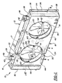
- Figure 1 illustrates an automotive engine cooling system 10, including a radiator 12, two engine cooling fans 14 shown in phantom, and a blow molded fan shroud arrangement 16.
- the latter arrangement 16 is blow molded (the mold parting line 17 is shown in phantom) to include a rectangular hollow body 18 of predetermined height, width and depth, and having dual openings 20 with respective cylindrical walls 22 and 23 formed therethrough and adapted to surround the outer peripheral paths of the two fans 14.
- the body 18 includes a front face 24, a rear face 26, a top wall 28, a bottom wall 30, and oppositely disposed side walls 32 and 34.
- a flange or tab 36 is formed on an edge of each side wall 32 and 34.
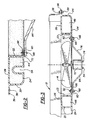
- the flanges 36 include spaced mounting holes 38 adapted to accommodate fasteners 39 to mount the body 18 on the radiator 12 of the vehicle involved, as shown in Figure 3.
- a pair of filler necks 40 and 42 are formed at spaced-apart locations along the top wall 28, for communicating with respective chambers 44 and 46 formed within the hollow body 18, adjacent and around the cylindrical walls 22, as will be explained.
- a pair of removable caps 48 are mounted on the filler necks 40 and 42.
- Oppositely disposed vertically oriented recesses 50 and 52 are formed in the respective front and rear faces 24 and 26 to provide walls 54 ( Figure 1) and 56 ( Figure 4) adjacent upper and lower portions of the cylindrical wall 22, serving to separate the chambers 44 and 46.
- Additional recesses such as the vertical recess 58 ( Figures 1 and 2), may be formed in the front face 24 to accommodate wire harnesses, hoses, or the like.
- Perforated tabs 60 and 62 are formed on opposite edges of each opening 20 to accommodate the mounting of fan assembly support brackets 64, as shown in Figures 2 and 3.
- a U-nut clip 66 is mounted around each tab 60 and 62, and a fastener 68 is mounted through aligned holes 70 formed in the clip 66 and each tab 60 and 62.
- a fan motor 72 is secured by suitable fasteners 74 to the inner surface of a U-shaped portion 76 of the support bracket 64.
- the chamber 44 is enclosed by the front and rear faces 24 and 26, the top wall 28, the side wall 32, the bottom wall 30, the walls of the recesses 50 and 52 adjacent the lower recessed wall 56 ( Figure 4), the cylindrical wall 22 ( Figure 2), and the walls of the recesses 50 and 52 adjacent the upper recessed wall 54 ( Figure 1).
- the chamber 46 encompasses a larger volume than the chamber 44, and is enclosed by the front and rear faces 24 and 26, top wall 28, the side wall 34, the bottom wall 30, the walls of the recesses 50 and 52 adjacent the lower separating recessed wall 56 ( Figure 4), the cylindrical wall 22, and the walls of the recesses 50 and 52 adjacent the upper separating recessed wall 54, while completely surrounding the cylindrical wall 23.
- the mold 80 design incorporates "tacks offs” to separate the chambers 44 and 46 in the molding process.
- an integral frame structure 82 may be compression molded during the blow molding process.
- the invention provides a compact cooling system structure which eliminates the need for space and fastening means for three separate components in the already crowded engine compartment of today's automobile. It provides substantial cost savings by virtue of having eliminated the need to manufacture and assemble three separate parts, while utilizing heretofore unused surface areas of the fan shroud.
- the invention may provide a standard or uniform structure which is unaffected by many new vehicular designs. Specifically, the shape of the compartments 44 and 46 need not be redesigned each time the fender wells and other interior parts are changed on at least some new vehicle models. Also, the integrally molded windshield washer fluid or headlamp washer fluid compartments may have a larger capacity than the previously employed separate containers.
- the resultant structure is extremely rigid, both radially and axially, and damped by fluid in the receptacles, reducing vibration or excitation of the fan shroud caused by the rotating fan surrounded thereby, hence diminishing a possible source of bothersome noise.
- inventive fan shroud and receptacle arrangement could be formed by one-piece gas assist injection molding, as well as by blow molding.
- the openings 20 are adaptable to having fans mounted therein which are belt-driven and attached to the motor.
Landscapes
- Engineering & Computer Science (AREA)
- Mechanical Engineering (AREA)
- General Engineering & Computer Science (AREA)
- Chemical & Material Sciences (AREA)
- Combustion & Propulsion (AREA)
- Physics & Mathematics (AREA)
- Thermal Sciences (AREA)
- Cooling, Air Intake And Gas Exhaust, And Fuel Tank Arrangements In Propulsion Units (AREA)
- Blow-Moulding Or Thermoforming Of Plastics Or The Like (AREA)
Claims (7)
- Gebläsegehäuse und Behälteranordnung zur Verwendung in der Nähe eines Fahrzeugkühlers und um eines oder mehrere Motorkühlgebläse herum, wobei die Anordnung einen geformten Hohlkörper einer bestimmten Tiefe umfasst, der eine Vorderseite, eine von der Vorderseite beabstandete Rückseite, eine obere Wand, eine untere Wand, gegenüberliegend angeordnete Seitenwände und wenigstens eine Öffnung durch den Körper aufweist, deren Größe so bemessen ist, dass sich ein Luftstrom durch den Fahrzeugkühler einstellt, und die eine diese umgebende zylindrische Wand aufweisen, wenigstens einen Satz von gegenüberliegend angeordneten Ausnehmungen aufweist, die in der Vorder- und Rückseite ausgebildet sind, um eine Wand zur Trennung des Hohlkörpers in zwei oder mehrere innere Kammern zu bilden, und Öffnungen in dem Körper zur Kommunikation mit den zwei oder mehr internen Kammern aufweist.
- Gebläsegehäuse und Behälteranordnung nach Anspruch 1, wobei die Wand zur Trennung des Hohlkörpers in zwei oder mehrere innere Kammern oberhalb und unterhalb der zylindrischen Wand ausgebildet ist.
- Gebläsegehäuse und Behälteranordnung nach Anspruch 2, umfassend zwei Öffnungen mit diese umgebenden zylindrischen Wänden.
- Gebläsegehäuse und Behälteranordnung nach Anspruch 3, bei welcher eine Kammer eine zylindrische Wand vollständig umgibt.
- Gebläsegehäuse und Behälteranordnung nach Anspruch 1, sowie Montagelaschen, die an gegenüberliegenden Seiten wenigstens einer Öffnung einstückig angeformt sind und die zur Aufnahme einer Halteklammer für eine Ventilatoranordnung ausgebildet sind.
- Gebläsegehäuse und Behälteranordnung nach Anspruch 1, bei welcher der Hohlkörper durch Blasformen ausgebildet ist.
- Gebläsegehäuse und Behälteranordnung nach Anspruch 6 und eine Rahmenstruktur, die so ausgebildet ist, dass sie einen Gebläsemotor aufnimmt und die während des Blasformens einstückig an den Hohlkörper angeformt wurde.
Applications Claiming Priority (3)
| Application Number | Priority Date | Filing Date | Title |
|---|---|---|---|
| US605981 | 1996-02-23 | ||
| US08/605,981 US5649587A (en) | 1996-02-23 | 1996-02-23 | Fan shroud and receptacle arrangement |
| PCT/US1997/001390 WO1997031182A1 (en) | 1996-02-23 | 1997-01-29 | Fan shroud and receptacle arrangement |
Publications (3)
| Publication Number | Publication Date |
|---|---|
| EP0882177A1 EP0882177A1 (de) | 1998-12-09 |
| EP0882177A4 EP0882177A4 (de) | 2004-03-24 |
| EP0882177B1 true EP0882177B1 (de) | 2006-10-18 |
Family
ID=24426014
Family Applications (1)
| Application Number | Title | Priority Date | Filing Date |
|---|---|---|---|
| EP97904051A Expired - Lifetime EP0882177B1 (de) | 1996-02-23 | 1997-01-29 | Ventilatorgehäuse |
Country Status (6)
| Country | Link |
|---|---|
| US (1) | US5649587A (de) |
| EP (1) | EP0882177B1 (de) |
| JP (1) | JP2000505171A (de) |
| CA (1) | CA2247153C (de) |
| DE (1) | DE69736829T2 (de) |
| WO (1) | WO1997031182A1 (de) |
Cited By (2)
| Publication number | Priority date | Publication date | Assignee | Title |
|---|---|---|---|---|
| CN103727065A (zh) * | 2014-01-13 | 2014-04-16 | 温岭市大洋电器厂 | 一种风机箱箱体及其转角接头 |
| DE102014002688A1 (de) | 2014-02-28 | 2015-09-03 | Kautex Textron Gmbh & Co. Kg | Mehrkammerbehälter |
Families Citing this family (58)
| Publication number | Priority date | Publication date | Assignee | Title |
|---|---|---|---|---|
| JP3293546B2 (ja) * | 1997-06-16 | 2002-06-17 | 株式会社デンソー | エンジン冷却装置のファンシュラウド |
| DE19826614A1 (de) | 1998-05-29 | 1999-12-02 | Basf Ag | Verfahren zur Herstellung von Hexandiol-1,6 |
| DE19828362B4 (de) * | 1998-06-25 | 2009-07-09 | Behr Gmbh & Co. Kg | Lüfterhaube für eine Wärmeübertrageranordnung eines Kraftfahrzeugs |
| US5971062A (en) * | 1998-07-22 | 1999-10-26 | Salflex Polymers Ltd. | Fan shroud with integrated reservoirs |
| MXPA01003866A (es) * | 1998-10-22 | 2002-05-06 | Mccord Winn Textron Inc | Guardera de ventilador y arreglo de admision de aire. |
| US6155335A (en) * | 1999-04-26 | 2000-12-05 | Delphi Technologies, Inc. | Vehicle fan shroud and component cooling module |
| US6692064B1 (en) | 1999-08-13 | 2004-02-17 | Conix Corporation | Reinforced blow-molded bumpers |
| US6401801B1 (en) | 1999-12-10 | 2002-06-11 | Caterpillar Inc. | Twin fan cooling system |
| US6988305B1 (en) * | 1999-12-17 | 2006-01-24 | Magna International Of America, Inc. | Method and apparatus for blow molding large reinforced plastic parts |
| US6499956B2 (en) | 2000-02-25 | 2002-12-31 | Inoac Corporation | Resonator-integrated fan shroud and resonator-integrated fan shroud with air intake duct |
| US6285547B1 (en) * | 2000-05-01 | 2001-09-04 | Hewlett-Packard Company | Bracket for retaining computer components within a housing |
| CA2413378A1 (en) | 2000-06-19 | 2001-12-27 | Stephen C. Hiltner | Blow molded fan shroud |
| DE10034326A1 (de) * | 2000-07-14 | 2002-01-24 | Mannesmann Vdo Ag | Einrichtung zur Speicherung von Waschwasser |
| US6318450B1 (en) | 2000-08-22 | 2001-11-20 | Delphi Technologies, Inc. | Fastener free automotive heat exchanger mounting |
| US6491502B2 (en) | 2000-08-23 | 2002-12-10 | Siemens Canada Limited | Center mounted fan module with even airflow distribution features |
| US20040142232A1 (en) * | 2000-11-30 | 2004-07-22 | Alex Risca | Space utilization/component integration using blow molding technology |
| EP1255028A3 (de) | 2001-05-03 | 2005-05-11 | Kautex Textron GmbH & Co. KG. | Blasgeformter Träger |
| DE10132602B4 (de) * | 2001-05-03 | 2004-05-13 | Kautex Textron Gmbh & Co. Kg | Blasgeformter Träger |
| US20040012125A1 (en) * | 2001-06-19 | 2004-01-22 | Plant William D. | Blow molded fan shroud |
| US6523507B2 (en) * | 2001-07-20 | 2003-02-25 | Kohler Co. | Fan shroud with snap-on coolant bottle |
| WO2003010031A2 (en) * | 2001-07-26 | 2003-02-06 | Collins & Aikman Automotive Company Inc. | Vehicle fascia support with integral fluid reservoir |
| US6622783B2 (en) | 2001-08-14 | 2003-09-23 | Modine Manufacturing Company | Self-fixturing fan shroud |
| US6749386B2 (en) | 2001-08-20 | 2004-06-15 | Maclean-Fogg Company | Locking fastener assembly |
| US6782908B2 (en) * | 2001-09-05 | 2004-08-31 | Ford Global Technologies, Llc | Automotive washer system utilizing a freezable washer liquid and a freeze-resistant washer liquid |
| US6561209B2 (en) | 2001-09-05 | 2003-05-13 | Ford Global Technologies, L.L.C. | Automotive washer system with a purge apparatus and a method therefore |
| US6871697B2 (en) | 2002-01-18 | 2005-03-29 | Clark Equipment Company | Integrated fluid reservoir and heat exchanger ducts |
| DE60315959T2 (de) * | 2002-03-15 | 2008-05-21 | Robert Bosch Llc | Motorgekühlte lüfteranordnung mit überlappenden flügeln |
| DE10328177A1 (de) * | 2003-06-17 | 2005-01-13 | Hydac System Gmbh | Fluidkühlvorrichtung |
| JP4638421B2 (ja) * | 2003-06-17 | 2011-02-23 | ハイダック システム ゲゼルシャフト ミット ベシュレンクテル ハフツング | 流体冷却装置 |
| DE10347872C5 (de) * | 2003-10-10 | 2006-12-14 | Wirtgen Gmbh | Selbstfahrende Strassenfräsmaschine mit Kühlsystem |
| US7465135B2 (en) | 2003-11-14 | 2008-12-16 | Maclean-Fogg Company | U-Nut fastening assembly |
| US20060048924A1 (en) * | 2004-08-31 | 2006-03-09 | Valeo, Inc. | Fluid reservoir for modular systems |
| FR2890634B1 (fr) * | 2005-09-09 | 2009-12-11 | Valeo Systemes Thermiques | Equipement pour face avant de vehicule automobile |
| EP2011977A1 (de) * | 2006-04-04 | 2009-01-07 | Calsonic Kansei Corporation | Wärmetauscher für fahrzeug |
| JP4577278B2 (ja) * | 2006-06-08 | 2010-11-10 | 株式会社デンソー | 内燃機関用吸気装置 |
| JP4367526B2 (ja) * | 2007-05-23 | 2009-11-18 | 株式会社デンソー | クーリングモジュール |
| US7640897B2 (en) * | 2007-08-08 | 2010-01-05 | Sauer-Danfoss, Inc. | Fan design and method of operating |
| US8291721B2 (en) * | 2008-02-25 | 2012-10-23 | Carrier Corporation | Dual condenser fans with center partition |
| US20090211287A1 (en) * | 2008-02-25 | 2009-08-27 | Carrier Corporation | Modular condenser fan assembly |
| JP5200880B2 (ja) * | 2008-11-19 | 2013-06-05 | ソニー株式会社 | 電子機器用送風装置及び電子機器 |
| DE102009060078A1 (de) * | 2009-11-18 | 2011-05-19 | Liebherr-Hausgeräte Lienz Gmbh | Halterungsanordnung für einen Ventilator, Baugruppe sowie Kühl- und/oder Gefriergerät |
| US8579060B2 (en) * | 2010-01-13 | 2013-11-12 | Demmer Corporation | Double heat exchanger radiator assembly |
| US8662840B2 (en) * | 2010-03-08 | 2014-03-04 | Robert Bosch Gmbh | Axial cooling fan shroud |
| TWI408290B (zh) * | 2010-07-16 | 2013-09-11 | Adda Corp | 風扇殼體組合結構 |
| US8646555B2 (en) | 2010-11-15 | 2014-02-11 | Honda Motor Company, Ltd. | Cooling system apparatus for a vehicle |
| US9611869B2 (en) * | 2013-07-17 | 2017-04-04 | Gardner Denver, Inc. | Slim mobile hydraulic fluid cooling assembly |
| DE202013011919U1 (de) * | 2013-11-25 | 2015-03-05 | Ebm-Papst Mulfingen Gmbh & Co. Kg | Lüfterbaueinheit |
| CN104405494B (zh) * | 2014-12-05 | 2016-11-30 | 璧山县和金汽车配件有限公司 | 一种集成式水箱与护罩连接总成 |
| JP2017019470A (ja) * | 2015-07-15 | 2017-01-26 | キャタピラー エス エー アール エル | 合成樹脂製タンク |
| JP6163518B2 (ja) * | 2015-07-23 | 2017-07-12 | 本田技研工業株式会社 | 冷却装置 |
| US10661650B2 (en) * | 2016-07-22 | 2020-05-26 | Nimer Ibrahim Shiheiber | Radiator system |
| US10563925B2 (en) * | 2017-07-12 | 2020-02-18 | Caterpillar Inc. | Cooling assembly for service vehicle |
| DE102018200475A1 (de) * | 2018-01-12 | 2019-07-18 | Ford Global Technologies, Llc | Kraftfahrzeug mit Kühlerabdeckung |
| DE102018201866B4 (de) * | 2018-02-07 | 2022-03-24 | Bayerische Motoren Werke Aktiengesellschaft | Kraftfahrzeug mit einem Frontend |
| DE102018219006A1 (de) * | 2018-11-07 | 2020-05-07 | Brose Fahrzeugteile SE & Co. Kommanditgesellschaft, Würzburg | Lüfteranordnung für ein Kraftfahrzeug |
| DE102018132002A1 (de) * | 2018-12-12 | 2020-06-18 | Ebm-Papst Mulfingen Gmbh & Co. Kg | Ventilationseinheit |
| CN111434930B (zh) * | 2019-01-11 | 2022-07-01 | 台达电子工业股份有限公司 | 风扇扇框 |
| DE102024001762A1 (de) | 2024-05-31 | 2025-06-18 | Mercedes-Benz Group AG | Vorderwagen eines Kraftfahrzeugs |
Family Cites Families (15)
| Publication number | Priority date | Publication date | Assignee | Title |
|---|---|---|---|---|
| US3692004A (en) * | 1971-05-03 | 1972-09-19 | Gen Motors Corp | Fan shroud and fluid receptacle arrangement |
| DE2221971C2 (de) * | 1972-05-05 | 1974-04-11 | Buderus'sche Eisenwerke, 6330 Wetzlar | Heizkörper aus thermoplastischem Material |
| US4030541A (en) * | 1974-06-08 | 1977-06-21 | Hoechst Aktiengesellschaft | Multi-element type radiator of plastic material |
| JPS55139224U (de) * | 1979-03-27 | 1980-10-04 | ||
| DE3444273C1 (de) * | 1984-12-05 | 1985-11-28 | Bayerische Motoren Werke AG, 8000 München | Aus Kunststoff hergestellter Wasserkasten fuer einen Querstrom-Kuehler fuer Brennkraftmaschinen |
| US4709757A (en) * | 1986-11-24 | 1987-12-01 | Johnson Service Company | Method of injection molding and plastic part formed thereby |
| JPS63154720U (de) * | 1987-03-30 | 1988-10-11 | ||
| US4762244A (en) * | 1987-09-23 | 1988-08-09 | Thermo King Corporation | Radiator overflow container |
| US4947931A (en) * | 1989-12-28 | 1990-08-14 | Vitacco Richard L | Plastic vehicular radiator-condenser with metal cooling inserts |
| DE9002438U1 (de) * | 1990-03-02 | 1990-04-12 | Süddeutsche Kühlerfabrik Julius Fr. Behr GmbH & Co KG, 7000 Stuttgart | Kunststoffwasserkasten für Wärmetauscher |
| US5012768A (en) * | 1990-04-19 | 1991-05-07 | Kloeckner-Humboldt-Deutz Ag | Cooling system |
| JPH0421722U (de) * | 1990-06-18 | 1992-02-24 | ||
| JP3338124B2 (ja) * | 1993-05-31 | 2002-10-28 | 三菱化学株式会社 | プロピレン系耐熱樹脂成形材料及びその成形体 |
| US5341871A (en) * | 1993-06-21 | 1994-08-30 | General Motors Corporation | Engine cooling fan assembly with snap-on retainers |
| JP3052725B2 (ja) * | 1994-03-30 | 2000-06-19 | 日産自動車株式会社 | 自動車用放熱装置 |
-
1996
- 1996-02-23 US US08/605,981 patent/US5649587A/en not_active Expired - Fee Related
-
1997
- 1997-01-29 JP JP9530160A patent/JP2000505171A/ja not_active Ceased
- 1997-01-29 EP EP97904051A patent/EP0882177B1/de not_active Expired - Lifetime
- 1997-01-29 CA CA002247153A patent/CA2247153C/en not_active Expired - Fee Related
- 1997-01-29 DE DE69736829T patent/DE69736829T2/de not_active Expired - Fee Related
- 1997-01-29 WO PCT/US1997/001390 patent/WO1997031182A1/en not_active Ceased
Cited By (4)
| Publication number | Priority date | Publication date | Assignee | Title |
|---|---|---|---|---|
| CN103727065A (zh) * | 2014-01-13 | 2014-04-16 | 温岭市大洋电器厂 | 一种风机箱箱体及其转角接头 |
| CN103727065B (zh) * | 2014-01-13 | 2016-04-27 | 温岭市大洋电器厂 | 一种风机箱箱体及其转角接头 |
| DE102014002688A1 (de) | 2014-02-28 | 2015-09-03 | Kautex Textron Gmbh & Co. Kg | Mehrkammerbehälter |
| US10094260B2 (en) | 2014-02-28 | 2018-10-09 | Kautex Textron Gmbh & Co. Kg | Multi-chamber container |
Also Published As
| Publication number | Publication date |
|---|---|
| DE69736829T2 (de) | 2007-03-15 |
| DE69736829D1 (de) | 2006-11-30 |
| JP2000505171A (ja) | 2000-04-25 |
| EP0882177A1 (de) | 1998-12-09 |
| CA2247153A1 (en) | 1997-08-28 |
| WO1997031182A1 (en) | 1997-08-28 |
| US5649587A (en) | 1997-07-22 |
| CA2247153C (en) | 2005-05-10 |
| EP0882177A4 (de) | 2004-03-24 |
Similar Documents
| Publication | Publication Date | Title |
|---|---|---|
| CA2247153C (en) | Fan shroud and receptacle arrangement | |
| EP0995895B1 (de) | Lüftergehäuse und Lufteinlassanordnung | |
| US3692004A (en) | Fan shroud and fluid receptacle arrangement | |
| CA2460314C (en) | Vehicle's intake device | |
| US6189492B1 (en) | Automotive fan shroud and method of making | |
| EP1071601B1 (de) | Fahrzeugmodul | |
| US6450276B1 (en) | Modular vehicle front end | |
| US20010018022A1 (en) | Resonator-integrated fan shroud and resonator-integrated fan shroud with air intake duct | |
| KR20060020594A (ko) | 플라스틱을 금속 부분에 부착하는 방법 및 그에 의해만들어진 부품 | |
| US6508506B2 (en) | Front end structure of vehicle | |
| US4441463A (en) | Container for fluids for operating functions in motor vehicles | |
| JP2003063332A (ja) | 燃料電池自動車の排気構造 | |
| JP2000264252A (ja) | 自動車の外気導入構造 | |
| JP5968336B2 (ja) | 燃焼機関のオイルパン | |
| EP1369576B1 (de) | Integriertes Motorraumbauelement und Luftansaugsystem | |
| JPH05105115A (ja) | フロントエンドパネル構造 | |
| US6308799B1 (en) | Integrated muffler-bumper system | |
| JPS6234836A (ja) | 自動車のトランクル−ム構造 | |
| US7191739B1 (en) | Integral coolant reservoir and air cleaner for automotive vehicle | |
| JPH0569020B2 (de) | ||
| EP0331644B1 (de) | Karosserieteil für ein Kraftfahrzeug und eine Karosserie, die ein solches Teil enthält | |
| EP1308373A1 (de) | Mehrfunktionaler Behälter für den Motorraum eines Kraftfahrzeuges | |
| EP1409327A2 (de) | Fahrzeugarmaturenbretthalter mit integralem fluidbehälter | |
| JP2001114131A (ja) | フロントエンドパネル | |
| WO2001074627A1 (en) | Structural beam with integrated knee energy absorbers |
Legal Events
| Date | Code | Title | Description |
|---|---|---|---|
| PUAI | Public reference made under article 153(3) epc to a published international application that has entered the european phase |
Free format text: ORIGINAL CODE: 0009012 |
|
| 17P | Request for examination filed |
Effective date: 19980905 |
|
| AK | Designated contracting states |
Kind code of ref document: A1 Designated state(s): DE ES FR GB IT |
|
| A4 | Supplementary search report drawn up and despatched |
Effective date: 20040211 |
|
| RIC1 | Information provided on ipc code assigned before grant |
Ipc: 7F 04D 29/58 B Ipc: 7F 01P 5/06 B Ipc: 7F 01P 11/02 B Ipc: 7F 01P 9/04 A |
|
| GRAP | Despatch of communication of intention to grant a patent |
Free format text: ORIGINAL CODE: EPIDOSNIGR1 |
|
| GRAS | Grant fee paid |
Free format text: ORIGINAL CODE: EPIDOSNIGR3 |
|
| GRAA | (expected) grant |
Free format text: ORIGINAL CODE: 0009210 |
|
| AK | Designated contracting states |
Kind code of ref document: B1 Designated state(s): DE ES FR GB IT |
|
| PG25 | Lapsed in a contracting state [announced via postgrant information from national office to epo] |
Ref country code: IT Free format text: LAPSE BECAUSE OF FAILURE TO SUBMIT A TRANSLATION OF THE DESCRIPTION OR TO PAY THE FEE WITHIN THE PRESCRIBED TIME-LIMIT;WARNING: LAPSES OF ITALIAN PATENTS WITH EFFECTIVE DATE BEFORE 2007 MAY HAVE OCCURRED AT ANY TIME BEFORE 2007. THE CORRECT EFFECTIVE DATE MAY BE DIFFERENT FROM THE ONE RECORDED. Effective date: 20061018 |
|
| REG | Reference to a national code |
Ref country code: GB Ref legal event code: FG4D |
|
| REF | Corresponds to: |
Ref document number: 69736829 Country of ref document: DE Date of ref document: 20061130 Kind code of ref document: P |
|
| PG25 | Lapsed in a contracting state [announced via postgrant information from national office to epo] |
Ref country code: ES Free format text: LAPSE BECAUSE OF FAILURE TO SUBMIT A TRANSLATION OF THE DESCRIPTION OR TO PAY THE FEE WITHIN THE PRESCRIBED TIME-LIMIT Effective date: 20070129 |
|
| ET | Fr: translation filed | ||
| PLBE | No opposition filed within time limit |
Free format text: ORIGINAL CODE: 0009261 |
|
| STAA | Information on the status of an ep patent application or granted ep patent |
Free format text: STATUS: NO OPPOSITION FILED WITHIN TIME LIMIT |
|
| 26N | No opposition filed |
Effective date: 20070719 |
|
| PGFP | Annual fee paid to national office [announced via postgrant information from national office to epo] |
Ref country code: GB Payment date: 20080124 Year of fee payment: 12 Ref country code: DE Payment date: 20080110 Year of fee payment: 12 |
|
| PGFP | Annual fee paid to national office [announced via postgrant information from national office to epo] |
Ref country code: FR Payment date: 20080111 Year of fee payment: 12 |
|
| GBPC | Gb: european patent ceased through non-payment of renewal fee |
Effective date: 20090129 |
|
| PG25 | Lapsed in a contracting state [announced via postgrant information from national office to epo] |
Ref country code: DE Free format text: LAPSE BECAUSE OF NON-PAYMENT OF DUE FEES Effective date: 20090801 |
|
| REG | Reference to a national code |
Ref country code: FR Ref legal event code: ST Effective date: 20091030 |
|
| PG25 | Lapsed in a contracting state [announced via postgrant information from national office to epo] |
Ref country code: GB Free format text: LAPSE BECAUSE OF NON-PAYMENT OF DUE FEES Effective date: 20090129 |
|
| PG25 | Lapsed in a contracting state [announced via postgrant information from national office to epo] |
Ref country code: FR Free format text: LAPSE BECAUSE OF NON-PAYMENT OF DUE FEES Effective date: 20090202 |