EP0882402A2 - Diaphragme - Google Patents
Diaphragme Download PDFInfo
- Publication number
- EP0882402A2 EP0882402A2 EP98109674A EP98109674A EP0882402A2 EP 0882402 A2 EP0882402 A2 EP 0882402A2 EP 98109674 A EP98109674 A EP 98109674A EP 98109674 A EP98109674 A EP 98109674A EP 0882402 A2 EP0882402 A2 EP 0882402A2
- Authority
- EP
- European Patent Office
- Prior art keywords
- segment
- segments
- diaphragm
- guide
- opening
- Prior art date
- Legal status (The legal status is an assumption and is not a legal conclusion. Google has not performed a legal analysis and makes no representation as to the accuracy of the status listed.)
- Granted
Links
- 235000013305 food Nutrition 0.000 claims description 13
- 235000011837 pasties Nutrition 0.000 claims description 6
- 238000005452 bending Methods 0.000 claims description 4
- 238000013519 translation Methods 0.000 claims description 3
- 230000000284 resting effect Effects 0.000 claims description 2
- 238000000034 method Methods 0.000 description 8
- 238000013461 design Methods 0.000 description 7
- 238000004140 cleaning Methods 0.000 description 3
- 230000003670 easy-to-clean Effects 0.000 description 3
- 238000003780 insertion Methods 0.000 description 3
- 230000037431 insertion Effects 0.000 description 3
- 230000000737 periodic effect Effects 0.000 description 3
- 238000011161 development Methods 0.000 description 2
- 230000001960 triggered effect Effects 0.000 description 2
- 230000001580 bacterial effect Effects 0.000 description 1
- 238000006073 displacement reaction Methods 0.000 description 1
- 238000007493 shaping process Methods 0.000 description 1
Images


Classifications
-
- A—HUMAN NECESSITIES
- A22—BUTCHERING; MEAT TREATMENT; PROCESSING POULTRY OR FISH
- A22C—PROCESSING MEAT, POULTRY, OR FISH
- A22C7/00—Apparatus for pounding, forming, or pressing meat, sausage-meat, or meat products
- A22C7/0015—Apparatus for pounding, forming, or pressing meat, sausage-meat, or meat products specially adapted for making meat-balls
-
- A—HUMAN NECESSITIES
- A21—BAKING; EDIBLE DOUGHS
- A21C—MACHINES OR EQUIPMENT FOR MAKING OR PROCESSING DOUGHS; HANDLING BAKED ARTICLES MADE FROM DOUGH
- A21C11/00—Other machines for forming the dough into its final shape before cooking or baking
- A21C11/10—Other machines for forming the dough into its final shape before cooking or baking combined with cutting apparatus
- A21C11/103—Other machines for forming the dough into its final shape before cooking or baking combined with cutting apparatus having multiple cutting elements slidably or rotably mounted in a diaphragm-like arrangement
Definitions
- the invention relates to a diaphragm for opening and closing an opening, in Specially for use in a dumpling machine, with several movable stored segments.
- the invention is particularly suitable for a dumpling device in the food industry, however, a diaphragm according to the invention can also be advantageous in other places are used in which an opening is closed and opened got to.
- Diaphragms are generally made up of a number of segments that are movably mounted.
- the individual segments essentially each lead one similar movement.
- An opening is created in one position, whereby the individual segments are arranged around this opening.
- the opening has a symmetry count, which corresponds at least to the number of segments and is from sub-areas the edges of the segments formed.
- Such diaphragms are e.g. used to paste pasty masses in individual volume units to divide.
- a dumpling machine e.g. the food mass pressed through the diaphragm and by opening and closing the same divided. It is desirable that the individual segments during the Do not overlap opening and closing process, otherwise there will be food mass can accumulate between the segment surfaces, which for hygienic reasons is undesirable.
- Diaphragms have therefore been proposed in which the segments have one Form that they can be assembled flat to cover the opening.
- the food mass should be divided by the diaphragm, e.g. dumplings are formed. Squeezes the mass of food while opening or closing the diaphragm on the diaphragm, the mass is also through Possibly openings 300a, 300b pressed between the individual segments open up. Accurate dosing and shaping is accordingly difficult.
- this object is achieved with a diaphragm which has the features of claim 1.
- An inventive diaphragm for opening and closing an opening with a plurality of movably mounted segments has a movement mechanism, of the individual segments with mutually similar movements between Can move positions in which the opening is closed or open, wherein the movements of the individual segments are made up of one translation and one Assemble rotation.
- each segment has at least one guide pin has, which is guided in a corresponding groove, at least in a partial area has a direction that consists of a tangential and an obliquely inward direction Direction is composed. This is an easy way to Determine the sequence of movements of the individual segments. The movement is controlled by the Guide pin in the groove and the sliding of the individual segments certainly.
- the shape of the individual segments is simply a triangle and one Semicircle composed, with the semicircle resting on one side of the triangle and the guide pin at the center of the semicircle on the virtual connection surface lies between the triangle and the semicircle.
- the triangular part the segments can easily be put together to form a closed surface to close the opening.
- the guide bolts comprise square bolts, which in the segments are rotatably supported. These square bolts can be in a corresponding Guide the guide groove very precisely to carry out the translatory movement. The rotational movement of the individual segments can easily be rotated around the Storage.
- the guide pins have a circular shape Cross section and form a rigid unit with the respective segment.
- Such Rigid unit is easy to clean and offers no way to get food mass in joints or pivot points.
- the circular cross section of the Guide pin ensures a smooth translation movement in the guide groove and enables a corresponding rotation.
- At least one spring element is provided for each segment Provision of the segment is provided in a starting position.
- the spring elements can be designed so that the closing of the diaphragm against the spring force happens. The opening of the diaphragm is then due to the Spring force automatically.
- these spring elements are spiral springs that surround the guide pin are arranged. This is a space-saving solution.
- spiral springs as spring elements, which are in the outer region of the diaphragm are arranged.
- Such spiral springs represent a simple one Solution and have advantages in terms of hygiene, since they are arranged outdoors and are not in contact with those passing through the opening of the diaphragm Can get mass. Such an arrangement is also easy to clean.
- the housing inner wall is not circular and has such a course that the angle between the spiral spring and the housing wall at the point of contact, at no point in the sequence of movements is of the order of 90 °.
- the design of the housing inner wall such that the angle between the spiral spring and the housing wall is not too large ensures reliable operation without the risk of the spiral spring jamming, especially when the diaphragm is opened again.
- each spiral spring In another development of such a diaphragm with spiral springs, this is first end of each spiral spring each connected to a segment and the second The end of each spiral spring slidably engages the adjacent segment.
- Such an arrangement of the spiral springs is independent of the housing wall. By the system on the adjacent segment is ensured that none are too large Angles of the spiral spring occur at the point of contact that lead to jamming being able to lead. Due to the housing is independent design of the spiral springs an even easier assembly secured. The cleaning is also strong in this way simplified.
- the respective point of attack of the second ends of the bending elements is advantageous on the respective outer surface removed from the opening of the diaphragm of the adjacent segment provided.
- Such an arrangement of the spiral springs enables a very space-saving and flat design of the diaphragm.
- a diaphragm according to the invention with a flexible spring for receiving the respective first end of the respective spiral spring in the corresponding Segment to provide a guide opening.
- a guide opening enables easy assembly and disassembly of the diaphragm.
- the diaphragm is advantageously constructed in such a way that the spring elements do not Are completely relaxed at the time. In this way, the spring elements preloaded, which ensures the mutual position of the segments in each position guaranteed.
- a particularly advantageous embodiment of the diaphragm according to the invention has a wavy circumferential guide groove in which all guide bolts are guided will.
- This guide groove can be designed so that the segments open the diaphragm opening close and open again when the guide bolts in the guide groove be guided along.
- Such a closed circumferential guide groove is particularly easy to clean. It is also possible to periodically open the diaphragm opening to open and close without returning the individual segments have to.
- the guide bolts always run in the same direction in the circumferential direction Guide groove around.
- the diaphragm there is a large number per segment of guide bolts provided in a corresponding plurality of guide grooves be performed.
- the individual segments moved by the individual guide pins in a kind of cam mechanism. This cam gear ensures the rotational and translational movement.
- the segments are simply designed as a triangle.
- eight segments can advantageously be used for one Diaphragm can be provided. With eight segments, an almost circular one can already Opening can be formed without causing an excessive number of segments the structure would be too complex.
- a diaphragm according to the invention is particularly advantageous for dividing one pasty mass can be used in predetermined volume units.
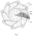
- FIG 7 a conventional diaphragm is shown, which is based on a rotational movement of the individual segments.
- Eight segments 100 are provided, which are around a pivot point 200 are rotatably mounted. With solid lines they are Segments 100 shown in the open diaphragm position. Dashed lines show the Segments 100 in the closed position or in an intermediate position. Hatched a segment 100 is shown as it is arranged when the diaphragm is closed is. With 300 is the opening that opens the opened diaphragm.
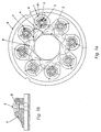
- Figure 1a shows a first embodiment of a diaphragm according to the invention in Top view in the open position.
- 1 denotes one of eight similar closure segments.
- the contour of such a segment is a semicircle 81 and a triangle 8 combined.
- the triangle has an angle ⁇ of 45 ° at shown embodiment with eight closure segments.
- On the segment a guide pin 2 is mounted on the underside (with respect to the viewing direction) can turn against the segment.
- the connection between the guide pin 2 and segment 1 is on the imaginary connecting line between the triangle 8 described above and the semicircle 81 at the center of the semicircle educated.
- the guide pin 2 is designed as a square, in upper section with a round cross-section.
- the square runs in a guide groove 4, the is located below the diaphragm.
- the guide groove 4 for each segment is 1 arranged at an angle, i.e. composed of a tangential component and a radial component seen with respect to the opening of the diaphragm.
- the inner end of the individual guide grooves 4 is at a distance from the center the diaphragm opening according to the distance of the guide pin from the Tip of the respective segment 1.
- the diaphragm is enclosed in a housing 6. 3 denotes the opening that opens the opened diaphragm.
- FIG. 1b A lateral cross section of a segment 1 is shown in FIG. 1b. You can see that Coil spring 5, which is placed around the guide pin 2. The coil spring 5 is on her outer end fixed to segment 1 and at its inner end to the guide pin 2. In Figure 1a, each individual segment by the coil spring 5 in the clockwise direction biased.
- the operation of the diaphragm of the first embodiment of the invention is as follows described. With the help of a mechanism, not shown, the Square of the guide pin 2 moves along the guide grooves 4.
- the movement mechanism can e.g. an externally driven wheel with an inner diameter be about the size of the outside diameter of the diaphragm, a pin pointing inwards from this inner diameter per segment, to the Guide pin 2 e.g. on the part that protrudes upward beyond the diaphragm.
- a rotation of such a wheel then leads to a displacement of the Guide bolts along the guide grooves 4, i.e. a translational movement.
- it is also any other mechanism for moving the guide bolts conceivable. Two adjacent segments 1 slide against each other on the contact surface 7 from.
- Such a diaphragm according to the invention can be used for portioning foods be used if there is e.g. a dumpling machine attached is.
- the pasty food mass is fed to the diaphragm through a pipe.
- Individual dumplings are molded by periodic opening and closing.
- FIG. 2a shows a top view of another embodiment of an inventive Diaphragm and Figure 2b shows a sectional view of a segment of this embodiment.
- Functionally identical elements are identified by the same reference numbers as in Figure 1.
- Each segment 1 is integrally rounded with a guide pin 20 Provide cross section. Similar to FIG. 1, this guide pin 20 runs in a guide groove 4.
- the restoring force for opening the diaphragm is at second embodiment by a spiral spring 50, e.g. a leaf spring posed.
- a spiral spring 50 is provided for each segment 1.
- One end the spiral spring 50 rests on the inner wall of the housing 6. The other end can be inserted into an insertion opening 9 of the corresponding segment. This makes the segment clockwise according to the figure shown biased.
- a third embodiment which is shown in Figure 3, the housing inner wall of the housing 6 with a backdrop 60 which is not circular. For each An almost linear area of this backdrop 60 is available for the segment. A spiral spring 51 is in contact with this linear surface of the backdrop 60.
- the special configuration the backdrop 60 ensures that the spiral spring 51 is always smooth along the Backdrop 60 can run without excessive bending angles leading to jamming can. Otherwise, the operation of the third embodiment is the same as that of second embodiment.
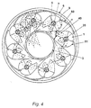
- Figure 4 shows a top view of a fourth embodiment.
- the springs and segments are of the same design as the second embodiment.
- a single guide groove 4 is not provided for each segment 1, but a wavy circumferential guide groove 40, in which all guide pins 20th run along.
- the smallest distance of this groove 40 from the center of the diaphragm opening corresponds to the distance of a guide pin 20 from the tip of the corresponding one Segment.
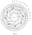
- FIG. 5 A fifth embodiment is shown in FIG. 5 in a top view.
- the guide bolts 20 run counterclockwise in a wavy guide groove 42, to move the segments 1 so that they close the opening 3.
- An intermediate state the opening is designated 30.
- Reduced the octagonal opening the further the individual segments 1 move counterclockwise.
- Spiral springs 52 are inserted into insertion holes 92 of the individual segments 1.
- the The second end of the spiral springs 52 lies on the respectively adjacent segment Touch surface 91 on.
- the tension of the spiral spring is chosen such that the Bending spring 52 pushes off at the contact point 91 to the segment in its insertion hole 92 it is attached to rotate clockwise.
- the segments are in the area 81, which is the tip of the respective segment 1 opposite, semi-circular.
- the spiral spring 52 slide on the respective segment at the contact point 91.
- This particular one Design of the spiral springs makes the diaphragm from the inner wall of the housing of the housing 6 independently.
- the individual segments 1 move over the intermediate state, the opening of which is designated 30, to the closed state.
- the intermediate state is marked with dash-dotted lines in FIG. How it works is similar to the fourth embodiment except for the spiral springs 52.
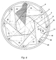
- Figure 6 shows a sixth embodiment.
- two guide pins 25, 26 circular Cross-section that can move in their own guide grooves 45 or 46. Due to the special shape of the guide grooves 45, 46, as indicated in FIG the movement of the segment is completely predetermined.
- Intermediate states are shown in dashed lines and the closed diaphragm state.
- bolts and grooves are only shown for a segment 11 in FIG. 6. Hatched the position of a segment 11 shown when the diaphragm is closed.
- the segments 11 lead to the sixth embodiment through a translatory and rotary movement. Here the surfaces 7 slide off one another without forming an additional opening.
Landscapes
- Life Sciences & Earth Sciences (AREA)
- Engineering & Computer Science (AREA)
- Food Science & Technology (AREA)
- Wood Science & Technology (AREA)
- Zoology (AREA)
- Diaphragms And Bellows (AREA)
- Manufacturing And Processing Devices For Dough (AREA)
- Actuator (AREA)
Applications Claiming Priority (2)
| Application Number | Priority Date | Filing Date | Title |
|---|---|---|---|
| DE19723228 | 1997-06-03 | ||
| DE19723228A DE19723228C2 (de) | 1997-06-03 | 1997-06-03 | Diaphragma |
Publications (3)
| Publication Number | Publication Date |
|---|---|
| EP0882402A2 true EP0882402A2 (fr) | 1998-12-09 |
| EP0882402A3 EP0882402A3 (fr) | 2000-06-07 |
| EP0882402B1 EP0882402B1 (fr) | 2002-08-28 |
Family
ID=7831257
Family Applications (1)
| Application Number | Title | Priority Date | Filing Date |
|---|---|---|---|
| EP98109674A Expired - Lifetime EP0882402B1 (fr) | 1997-06-03 | 1998-05-27 | Diaphragme |
Country Status (2)
| Country | Link |
|---|---|
| EP (1) | EP0882402B1 (fr) |
| DE (2) | DE19723228C2 (fr) |
Cited By (5)
| Publication number | Priority date | Publication date | Assignee | Title |
|---|---|---|---|---|
| FR2840157A1 (fr) * | 2002-05-28 | 2003-12-05 | Young Robert Ou | Dispositif de moulage pour des produits a base de pate |
| WO2013139853A1 (fr) * | 2012-03-20 | 2013-09-26 | Marel France | Procede et machine de fabrication de portions avec moyens d'ejection desdites portions |
| EP1964471A4 (fr) * | 2005-12-21 | 2014-04-30 | Rheon Automatic Machinery Co | Dispositif d obturation de mise en forme et element d obturation |
| CN108935560A (zh) * | 2018-08-17 | 2018-12-07 | 成都松川雷博机械设备有限公司 | 一种包馅食品成型方法 |
| CN113229313A (zh) * | 2021-05-14 | 2021-08-10 | 许昌学院 | 一种防止粘连的食品加工用肉丸加工装置 |
Family Cites Families (8)
| Publication number | Priority date | Publication date | Assignee | Title |
|---|---|---|---|---|
| DE168501C (fr) * | ||||
| US3292207A (en) * | 1964-06-08 | 1966-12-20 | James E Herrick | Machine for automatically making meatballs and the like |
| AU643818B2 (en) * | 1990-09-12 | 1993-11-25 | Rheon Automatic Machinery Co. Ltd. | Apparatus for cutting an enveloped body |
| JPH084443B2 (ja) * | 1992-01-30 | 1996-01-24 | 株式会社コバード | 可塑性棒状食品切断機 |
| TW213852B (fr) * | 1992-03-30 | 1993-10-01 | Reon Zidoki Kk | |
| GB9515328D0 (en) * | 1995-07-26 | 1995-09-20 | Willson Peter D W | Apparatus for modifying light quality:-diaphagm,colour changer and dimmer |
| DE19603659C2 (de) * | 1996-02-02 | 2003-11-06 | Merritt Brigitte | Vorrichtung zum Einschnüren und Abtrennen eines Stranges aus plastischem Material |
| JP3016246B2 (ja) * | 1996-09-25 | 2000-03-06 | レオン自動機株式会社 | 包被切断装置 |
-
1997
- 1997-06-03 DE DE19723228A patent/DE19723228C2/de not_active Expired - Fee Related
-
1998
- 1998-05-27 EP EP98109674A patent/EP0882402B1/fr not_active Expired - Lifetime
- 1998-05-27 DE DE59805287T patent/DE59805287D1/de not_active Expired - Fee Related
Non-Patent Citations (1)
| Title |
|---|
| None |
Cited By (9)
| Publication number | Priority date | Publication date | Assignee | Title |
|---|---|---|---|---|
| FR2840157A1 (fr) * | 2002-05-28 | 2003-12-05 | Young Robert Ou | Dispositif de moulage pour des produits a base de pate |
| EP1964471A4 (fr) * | 2005-12-21 | 2014-04-30 | Rheon Automatic Machinery Co | Dispositif d obturation de mise en forme et element d obturation |
| WO2013139853A1 (fr) * | 2012-03-20 | 2013-09-26 | Marel France | Procede et machine de fabrication de portions avec moyens d'ejection desdites portions |
| FR2988266A1 (fr) * | 2012-03-20 | 2013-09-27 | Marel Stork Food Systems France Sas | Procede et machine de fabrication de portions avec moyens d'ejection desdites portions |
| US9877491B2 (en) | 2012-03-20 | 2018-01-30 | Marel France | Method and machine for the production of portions, including means for ejecting said portions |
| CN108935560A (zh) * | 2018-08-17 | 2018-12-07 | 成都松川雷博机械设备有限公司 | 一种包馅食品成型方法 |
| CN108935560B (zh) * | 2018-08-17 | 2020-11-27 | 成都松川雷博机械设备有限公司 | 一种包馅食品成型方法 |
| CN113229313A (zh) * | 2021-05-14 | 2021-08-10 | 许昌学院 | 一种防止粘连的食品加工用肉丸加工装置 |
| CN113229313B (zh) * | 2021-05-14 | 2023-02-28 | 许昌学院 | 一种防止粘连的食品加工用肉丸加工装置 |
Also Published As
| Publication number | Publication date |
|---|---|
| DE19723228A1 (de) | 1998-12-10 |
| DE59805287D1 (de) | 2002-10-02 |
| DE19723228C2 (de) | 1999-11-11 |
| EP0882402A3 (fr) | 2000-06-07 |
| EP0882402B1 (fr) | 2002-08-28 |
Similar Documents
| Publication | Publication Date | Title |
|---|---|---|
| DD200850A5 (de) | Uebertragungsvorrichtung fuer staebchenfoermige artikel | |
| DE1928788A1 (de) | Betaetigungsvorrichtung mit drehbarem Einstellglied,insbesondere fuer Schalter | |
| DE3710356A1 (de) | Loescheinrichtung fuer einen drehstellungs-anzeigeschalter | |
| DE3941352C2 (de) | Elektromotorisches Stellglied | |
| DE3044572C2 (de) | Vorrichtung zur Steuerung der durch den Schlauch einer Infusionsvorrichtung hindurchströmenden Flüssigkeitsmenge | |
| EP0882402B1 (fr) | Diaphragme | |
| EP3084246A1 (fr) | Dispositif articulé entre un arbre d'entraînement et un arbre de sortie | |
| EP0415937A1 (fr) | Entrainement a declic par ressort de commutateurs de reglage en charge de commutateurs a gradins | |
| DE1289708B (de) | Vorrichtung zum Umwandeln einer Drehbewegung in eine Translationsbewegung, insbesondere zum Betaetigen des Verschlussgliedes eines Ventils, mit zwei gegeneinander verdrehbaren, exzentrisch gelagerten Scheiben unterschiedlichen Durchmessers und einem die groessere Scheibe umgreifenden, dagegen verdrehbaren und mit einem axial verschieblich gefuehrten Koppelorgan verbundenen Ring | |
| DE3423979A1 (de) | Schrauben-schraubenmutter-kupplung mit kugelumlauf und verfahren zu ihrem zusammenbau | |
| DE3518419A1 (de) | Betaetigungsvorrichtung fuer einen schalter | |
| DE3340042C2 (de) | Vorrichtung für die alternierende Druckluftspeisung eines Schußfadenmischers an einer schützenlosen Webmaschine mit pneumatischem Schußfadeneintrag | |
| DE2165407C3 (de) | Permutationsschalter | |
| DE1289628B (de) | Einrichtung zum Verbinden der beiden Gehaeusehaelften eines Staubsaugers | |
| DE7237970U (de) | Scharniervorrichtung fuer eine tuer | |
| DE2208428A1 (de) | Drehschalter, insbesondere nockenschalter | |
| EP0132671B1 (fr) | Générateur d'impulsions | |
| DE3005500A1 (de) | Zaehlwerk | |
| EP3078454A1 (fr) | Dispositif comprenant une surface de prehension parallele | |
| DE3231352C1 (de) | Vorrichtung zur Umwandlung einer geradlinigen Bewegung in eine Drehbewegung | |
| DE69832917T2 (de) | Mikrowellenschalter | |
| DE1556535A1 (de) | Selbsttaetige Drehverteilerscheibe | |
| DE102010033513B3 (de) | Verriegelungsvorrichtung | |
| DE102008027716A1 (de) | Vorrichtung zum Umwandeln einer linearen Hin- und Herbewegung in eine intermittierende Drehbewegung | |
| EP0949434B1 (fr) | Transmission à vis |
Legal Events
| Date | Code | Title | Description |
|---|---|---|---|
| PUAI | Public reference made under article 153(3) epc to a published international application that has entered the european phase |
Free format text: ORIGINAL CODE: 0009012 |
|
| AK | Designated contracting states |
Kind code of ref document: A2 Designated state(s): CH DE LI NL |
|
| AX | Request for extension of the european patent |
Free format text: AL;LT;LV;MK;RO;SI |
|
| PUAL | Search report despatched |
Free format text: ORIGINAL CODE: 0009013 |
|
| AK | Designated contracting states |
Kind code of ref document: A3 Designated state(s): AT BE CH CY DE DK ES FI FR GB GR IE IT LI LU MC NL PT SE |
|
| AX | Request for extension of the european patent |
Free format text: AL;LT;LV;MK;RO;SI |
|
| RIC1 | Information provided on ipc code assigned before grant |
Free format text: 7A 22C 7/00 A, 7A 21C 11/10 B |
|
| 17P | Request for examination filed |
Effective date: 20000718 |
|
| AKX | Designation fees paid |
Free format text: CH DE LI NL |
|
| 17Q | First examination report despatched |
Effective date: 20010730 |
|
| GRAG | Despatch of communication of intention to grant |
Free format text: ORIGINAL CODE: EPIDOS AGRA |
|
| GRAG | Despatch of communication of intention to grant |
Free format text: ORIGINAL CODE: EPIDOS AGRA |
|
| GRAH | Despatch of communication of intention to grant a patent |
Free format text: ORIGINAL CODE: EPIDOS IGRA |
|
| GRAH | Despatch of communication of intention to grant a patent |
Free format text: ORIGINAL CODE: EPIDOS IGRA |
|
| GRAA | (expected) grant |
Free format text: ORIGINAL CODE: 0009210 |
|
| AK | Designated contracting states |
Kind code of ref document: B1 Designated state(s): CH DE LI NL |
|
| REG | Reference to a national code |
Ref country code: CH Ref legal event code: NV Representative=s name: PATENTANWALTSBUERO JEAN HUNZIKER Ref country code: CH Ref legal event code: EP |
|
| REF | Corresponds to: |
Ref document number: 59805287 Country of ref document: DE Date of ref document: 20021002 |
|
| PG25 | Lapsed in a contracting state [announced via postgrant information from national office to epo] |
Ref country code: LI Free format text: LAPSE BECAUSE OF NON-PAYMENT OF DUE FEES Effective date: 20030531 Ref country code: CH Free format text: LAPSE BECAUSE OF NON-PAYMENT OF DUE FEES Effective date: 20030531 |
|
| PGFP | Annual fee paid to national office [announced via postgrant information from national office to epo] |
Ref country code: DE Payment date: 20030627 Year of fee payment: 6 |
|
| PLBE | No opposition filed within time limit |
Free format text: ORIGINAL CODE: 0009261 |
|
| STAA | Information on the status of an ep patent application or granted ep patent |
Free format text: STATUS: NO OPPOSITION FILED WITHIN TIME LIMIT |
|
| 26N | No opposition filed |
Effective date: 20030530 |
|
| PG25 | Lapsed in a contracting state [announced via postgrant information from national office to epo] |
Ref country code: NL Free format text: LAPSE BECAUSE OF NON-PAYMENT OF DUE FEES Effective date: 20031201 |
|
| REG | Reference to a national code |
Ref country code: CH Ref legal event code: PL |
|
| NLV4 | Nl: lapsed or anulled due to non-payment of the annual fee |
Effective date: 20031201 |
|
| PG25 | Lapsed in a contracting state [announced via postgrant information from national office to epo] |
Ref country code: DE Free format text: LAPSE BECAUSE OF NON-PAYMENT OF DUE FEES Effective date: 20041201 |