EP0882467B1 - Seringue medicale - Google Patents
Seringue medicale Download PDFInfo
- Publication number
- EP0882467B1 EP0882467B1 EP98116586A EP98116586A EP0882467B1 EP 0882467 B1 EP0882467 B1 EP 0882467B1 EP 98116586 A EP98116586 A EP 98116586A EP 98116586 A EP98116586 A EP 98116586A EP 0882467 B1 EP0882467 B1 EP 0882467B1
- Authority
- EP
- European Patent Office
- Prior art keywords
- barrel
- syringe
- plunger rod
- brake
- rod assembly
- Prior art date
- Legal status (The legal status is an assumption and is not a legal conclusion. Google has not performed a legal analysis and makes no representation as to the accuracy of the status listed.)
- Expired - Lifetime
Links
- 230000000295 complement effect Effects 0.000 claims 4
- 239000012530 fluid Substances 0.000 claims 3
- 238000000926 separation method Methods 0.000 description 3
- NOESYZHRGYRDHS-UHFFFAOYSA-N insulin Chemical compound N1C(=O)C(NC(=O)C(CCC(N)=O)NC(=O)C(CCC(O)=O)NC(=O)C(C(C)C)NC(=O)C(NC(=O)CN)C(C)CC)CSSCC(C(NC(CO)C(=O)NC(CC(C)C)C(=O)NC(CC=2C=CC(O)=CC=2)C(=O)NC(CCC(N)=O)C(=O)NC(CC(C)C)C(=O)NC(CCC(O)=O)C(=O)NC(CC(N)=O)C(=O)NC(CC=2C=CC(O)=CC=2)C(=O)NC(CSSCC(NC(=O)C(C(C)C)NC(=O)C(CC(C)C)NC(=O)C(CC=2C=CC(O)=CC=2)NC(=O)C(CC(C)C)NC(=O)C(C)NC(=O)C(CCC(O)=O)NC(=O)C(C(C)C)NC(=O)C(CC(C)C)NC(=O)C(CC=2NC=NC=2)NC(=O)C(CO)NC(=O)CNC2=O)C(=O)NCC(=O)NC(CCC(O)=O)C(=O)NC(CCCNC(N)=N)C(=O)NCC(=O)NC(CC=3C=CC=CC=3)C(=O)NC(CC=3C=CC=CC=3)C(=O)NC(CC=3C=CC(O)=CC=3)C(=O)NC(C(C)O)C(=O)N3C(CCC3)C(=O)NC(CCCCN)C(=O)NC(C)C(O)=O)C(=O)NC(CC(N)=O)C(O)=O)=O)NC(=O)C(C(C)CC)NC(=O)C(CO)NC(=O)C(C(C)O)NC(=O)C1CSSCC2NC(=O)C(CC(C)C)NC(=O)C(NC(=O)C(CCC(N)=O)NC(=O)C(CC(N)=O)NC(=O)C(NC(=O)C(N)CC=1C=CC=CC=1)C(C)C)CC1=CN=CN1 NOESYZHRGYRDHS-UHFFFAOYSA-N 0.000 description 2
- 238000004519 manufacturing process Methods 0.000 description 2
- 238000004659 sterilization and disinfection Methods 0.000 description 2
- 102000004877 Insulin Human genes 0.000 description 1
- 108090001061 Insulin Proteins 0.000 description 1
- 239000004743 Polypropylene Substances 0.000 description 1
- 229940125396 insulin Drugs 0.000 description 1
- 239000000463 material Substances 0.000 description 1
- 238000000034 method Methods 0.000 description 1
- -1 polypropylene Polymers 0.000 description 1
- 229920001155 polypropylene Polymers 0.000 description 1
Images
Classifications
-
- A—HUMAN NECESSITIES
- A61—MEDICAL OR VETERINARY SCIENCE; HYGIENE
- A61M—DEVICES FOR INTRODUCING MEDIA INTO, OR ONTO, THE BODY; DEVICES FOR TRANSDUCING BODY MEDIA OR FOR TAKING MEDIA FROM THE BODY; DEVICES FOR PRODUCING OR ENDING SLEEP OR STUPOR
- A61M5/00—Devices for bringing media into the body in a subcutaneous, intra-vascular or intramuscular way; Accessories therefor, e.g. filling or cleaning devices, arm-rests
- A61M5/178—Syringes
- A61M5/31—Details
- A61M5/315—Pistons; Piston-rods; Guiding, blocking or restricting the movement of the rod or piston; Appliances on the rod for facilitating dosing ; Dosing mechanisms
-
- A—HUMAN NECESSITIES
- A61—MEDICAL OR VETERINARY SCIENCE; HYGIENE
- A61M—DEVICES FOR INTRODUCING MEDIA INTO, OR ONTO, THE BODY; DEVICES FOR TRANSDUCING BODY MEDIA OR FOR TAKING MEDIA FROM THE BODY; DEVICES FOR PRODUCING OR ENDING SLEEP OR STUPOR
- A61M5/00—Devices for bringing media into the body in a subcutaneous, intra-vascular or intramuscular way; Accessories therefor, e.g. filling or cleaning devices, arm-rests
- A61M5/178—Syringes
- A61M5/31—Details
- A61M5/3129—Syringe barrels
- A61M5/3137—Specially designed finger grip means, e.g. for easy manipulation of the syringe rod
- A61M2005/3139—Finger grips not integrally formed with the syringe barrel, e.g. using adapter with finger grips
-
- A—HUMAN NECESSITIES
- A61—MEDICAL OR VETERINARY SCIENCE; HYGIENE
- A61M—DEVICES FOR INTRODUCING MEDIA INTO, OR ONTO, THE BODY; DEVICES FOR TRANSDUCING BODY MEDIA OR FOR TAKING MEDIA FROM THE BODY; DEVICES FOR PRODUCING OR ENDING SLEEP OR STUPOR
- A61M5/00—Devices for bringing media into the body in a subcutaneous, intra-vascular or intramuscular way; Accessories therefor, e.g. filling or cleaning devices, arm-rests
- A61M5/178—Syringes
- A61M5/31—Details
- A61M5/315—Pistons; Piston-rods; Guiding, blocking or restricting the movement of the rod or piston; Appliances on the rod for facilitating dosing ; Dosing mechanisms
- A61M5/31501—Means for blocking or restricting the movement of the rod or piston
- A61M5/31505—Integral with the syringe barrel, i.e. connected to the barrel so as to make up a single complete piece or unit
Definitions
- the invention pertains to a syringe for medicinal purposes, with a syringe barrel, one end of which is designed as an adapter for a cannula or a closure piece, e.g., in the form of a tip cap, and with a plunger arranged in the syringe barrel and movable via a piston rod.
- Syringes of this type are increasingly being marketed, especially as ready-to-use syringes in prefilled form, for self-administration by the patient, as has long been the case, especially for regular administration of insulin in diabetics.
- US-A-4,267,846 discloses a syringe having a piston brake attached to the syringe barrel.
- the piston brake acts on the piston for controlling the distance in which the piston can move in both inward and outward directions.
- the syringe barrel has at its proximal end a flange extending perpendicular to the longitudinal axis of the barrel and providing a finger grip for the user of the syringe during its operation.
- the piston brake has a hook sized and shaped to snap fit over the flange for fastening the piston brake to the barrel. This requires that the barrel has a flange or other protrusion for fastening the piston brake.
- there exist syringes which do not have a flange on the barrel.
- the rest piece housing includes a circularly shaped side wall having an inside surface contacting the outer surface of the open proximal end of the barrel and includes two radially outwardly projecting wings, said wings forming a finger rest for applying axial force to the barrel.
- a plunger brake is arranged, which is formed by a rest piece surrounding the syringe barrel and attached removably to it, which has a projection extending into the lumen of the barrel, which forms a stop for the side of the plunger away from the adapter.
- the annular piece has two radially extending, diametrically opposite wings that form a finger rest. This is especially advantageous when syringes with very small volumes are used.
- the advantage achieved with the invention lies, first of all, in the fact that the projection extending into the lumen of the syringe barrel exerts a braking effect on the plunger, so that even in the case of incorrect manipulation of the syringe by the patient during use, so long as excessive force is not applied, the plunger cannot come out of the syringe barrel.
- the plunger brake prevents the plunger from being forced out of the barrel, for example, by an air bubble present in the barrel.
- the plunger brake can be sterilized along with the unit, if, for example, this is made of polypropylene.
- the pharmaceutical safety of the syringe as a whole is increased. Since the plunger brake is placed removably on the syringe barrel, it can be removed from the syringe after use; disposal is simplified by separation of the different materials.
- the rest piece is designed as an annular piece, and the projection is designed as fingers extending axially into the barrel, wherein the freely projecting end of the finger forms the stop for the plunger.
- the annular piece has a separation slit on the side opposite the finger. In this way, the annular piece can especially easily be clipped onto the barrel from the side.
- the annular piece is sleeve-shaped, so that it does not interfere with handling of the syringe.
- the annular piece can be provided on its outer surface with a riffling travelling in the circumferential direction. This provides additional security when holding or handling the syringe.
- the invention also provides that the piston rod is tapered in the area adjacent to the piston rod thread provided for connection to the plunger.
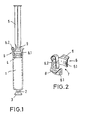
- the syringe for medicinal purposes shown in the drawing consists of a syringe barrel 1, one end of which is designed as an adapter 2 for a cannula or - as shown in Fig. 1 - for a closure piece 3 in the form of a tip cap.
- a plunger 4 is arranged, which can be moved with the aid of a piston rod 5.
- the plunger brake 6 consists, in detail, in a first embodiment shown in Figures 1 and 2, of a first annular piece 6.1, surrounding the barrel 1, and a finger 6.2 projecting into the interior of the barrel 1, connected to the annular piece 6.1.
- the free end of the finger 6.2 forms a stop for the plunger 4.
- the plunger brake 6 prevents the plunger 4 from being accidentally pulled out of the barrel 1 in the case of incorrect use of the syringe, for example by a unskilled patient.
- the plunger brake 6 prevents, for example, the plunger 4 from being forced out of the barrel 1 due to excess pressure occurring in the interior during the post-sterilization of solutions previously filled into the barrel 1.
- the annular portion 6.1 of the plunger brake 6, as shown in Fig. 2, consists of a separation slit 7 located on the side opposite the finger 6.2, as a result of which the plunger brake 6 can be clipped especially easily onto the syringe barrel 1 from the side.
- the annular portion 6.1 itself has an essentially sleeve-like shape, and is thus adapted in shape to the syringe barrel 1.
- the annular piece 6.1 can be provided, in a way not shown in detail in the drawing, on its outer surface, with a riffling running in the circumferential direction. In addition, or alternatively. As shown in Fig. 2, the annular piece 6.1 is provided with two radially extending, diametrically opposite wings 8, which form a finger rest. This is especially advantageous in the case of barrels with relatively small volume, since these generally do not have finger rests.
- Fig. 1 shows, the finger 6.2 lies against the inner wall of the syringe barrel 1, so that the piston rod 5 can be moved freely.
- the piston rod 5 is tapered in the area 9 adjacent to the piston rod threads, so that the piston rod threads can be screwed into the plunger 4 without further efford, even when the plunger brake 6 is clipped into place.
Landscapes
- Health & Medical Sciences (AREA)
- Vascular Medicine (AREA)
- Engineering & Computer Science (AREA)
- Anesthesiology (AREA)
- Biomedical Technology (AREA)
- Heart & Thoracic Surgery (AREA)
- Hematology (AREA)
- Life Sciences & Earth Sciences (AREA)
- Animal Behavior & Ethology (AREA)
- General Health & Medical Sciences (AREA)
- Public Health (AREA)
- Veterinary Medicine (AREA)
- Infusion, Injection, And Reservoir Apparatuses (AREA)
Claims (8)
- Seringue comprenant un corps creux allongé (1) ayant une extrémité distale, une extrémité proximale ouverte et une chambre entre celles-ci pour retenir un fluide, une pointe à ladite extrémité distale dudit corps, traversée par un passage en communication fluide avec ladite chambre, un assemblage de tige de piston (4, 5) comprenant un piston (4) en prise fluide étroite par glissement à l'intérieur dudit corps (1), et une tige de piston allongée (5) connectée audit piston (4), et s'étendant de manière proximale à travers ladite extrémité ouverte dudit corps (1), un frein de l'assemblage de tige de piston (6) fixé de manière amovible à ladite extrémité proximale ouverte dudit corps (1), comprenant une partie de logement de pièce de repos entourant partiellement et en prise de manière amovible avec la surface externe de ladite extrémité proximale ouverte dudit corps (1), une projection dudit frein (6) pour être en prise avec une saillie complémentaire sur ledit assemblage de tige de piston (4, 5), de telle sorte que le mouvement proximal dudit assemblage de tige de piston (4, 5) par rapport audit corps (1) provoquera la prise de ladite projection de frein et de ladite saillie complémentaire, et évitera le retrait dudit assemblage de tige de piston (4, 5) dudit corps (1) au cours d'une utilisation normale de ladite seringue,
ledit logement de pièce de repos comprenant une paroi latérale de forme circulaire (6.1), ayant une surface interne en contact avec la surface externe de l'extrémité proximale ouverte du corps (1),
caractérisée en ce que
ladite paroi latérale (6.1) comprend deux ailes à projection externe radiale (8), lesdites ailes (8) formant un repos de doigt pour appliquer une force axiale audit corps (1). - Seringue suivant la revendication 1, dans laquelle ladite projection de frein comprend au moins un doigt (6.2) s'étendant axialement dans ladite chambre, ledit au moins un doigt (6.2) comprenant une extrémité distale ayant une surface d'extrémité pour entrer en contact avec ladite saillie complémentaire dudit assemblage de tige de piston (4,5) pour éviter le retrait dudit assemblage de tige de piston (4, 5) dudit corps (1).
- Seringue suivant la revendication 2, dans laquelle ledit doigt (6.2) est en une relation de contact avec ledit corps (1) dans ladite chambre.
- Seringue suivant l'une des revendications 1-3, dans laquelle ladite paroi latérale de forme circulaire (6.1) comprend une discontinuité inférieure à 180°.
- Seringue suivant la revendication 4, dans laquelle ladite discontinuité se trouve sur le côté opposé dudit frein à partir de ladite saillie.
- Seringue suivant l'une des revendications 1-5, dans laquelle ladite partie de logement de pièce de repos est en forme de manchon.
- Seringue suivant l'une quelconque des revendications 1-6, dans laquelle ladite saillie complémentaire comprend une structure en forme de disque sur ladite tige de piston (5) essentiellement perpendiculaire à l'axe longitudinal de ladite tige de piston (5).
- Seringue suivant la revendication 7, dans laquelle ladite structure en forme de disque a un diamètre externe de forme frusto-conique effilée.
Applications Claiming Priority (5)
| Application Number | Priority Date | Filing Date | Title |
|---|---|---|---|
| DE4314987 | 1993-05-06 | ||
| DE4314987 | 1993-05-06 | ||
| DE4331137A DE4331137A1 (de) | 1993-05-06 | 1993-09-14 | Spritze für medizinische Zwecke |
| DE4331137 | 1993-09-14 | ||
| EP94916186A EP0649318B1 (fr) | 1993-05-06 | 1994-05-03 | Seringue a usage medical |
Related Parent Applications (1)
| Application Number | Title | Priority Date | Filing Date |
|---|---|---|---|
| EP94916186A Division EP0649318B1 (fr) | 1993-05-06 | 1994-05-03 | Seringue a usage medical |
Publications (3)
| Publication Number | Publication Date |
|---|---|
| EP0882467A2 EP0882467A2 (fr) | 1998-12-09 |
| EP0882467A3 EP0882467A3 (fr) | 1999-10-13 |
| EP0882467B1 true EP0882467B1 (fr) | 2003-10-01 |
Family
ID=6487324
Family Applications (1)
| Application Number | Title | Priority Date | Filing Date |
|---|---|---|---|
| EP98116586A Expired - Lifetime EP0882467B1 (fr) | 1993-05-06 | 1994-05-03 | Seringue medicale |
Country Status (2)
| Country | Link |
|---|---|
| EP (1) | EP0882467B1 (fr) |
| DE (3) | DE4331137A1 (fr) |
Cited By (4)
| Publication number | Priority date | Publication date | Assignee | Title |
|---|---|---|---|---|
| US7951120B2 (en) | 2003-06-04 | 2011-05-31 | Schott Ag | Method for manufacturing a syringe |
| US9387292B2 (en) | 2010-05-05 | 2016-07-12 | Safety Syringes, Inc. | Extended finger flange for syringe systems |
| US10925927B2 (en) | 2015-11-18 | 2021-02-23 | Formycon Ag | Pre-filled pharmaceutical package comprising a liquid formulation of a VEGF-antagonist |
| US11654046B2 (en) | 2015-11-18 | 2023-05-23 | Sio2 Medical Products, Inc. | Pharmaceutical package for ophthalmic formulations |
Families Citing this family (8)
| Publication number | Priority date | Publication date | Assignee | Title |
|---|---|---|---|---|
| DE19613035B4 (de) * | 1996-03-19 | 2007-12-13 | Ferring Gmbh | System mit einer Spritze und einem Griffstück |
| DE19929325A1 (de) * | 1999-06-26 | 2001-01-18 | Vetter & Co Apotheker | Spritze für medizinische Zwecke |
| DE10220034A1 (de) * | 2002-05-04 | 2003-11-20 | Schott Glas | Spritze, insbesondere eine vorgefüllte Einmalspritze |
| DE10252220B3 (de) | 2002-11-11 | 2004-05-13 | Schott Glas | Medizinische Spritze |
| FR2855413B1 (fr) * | 2003-05-26 | 2005-12-30 | Becton Dickinson France | Seringue pre-remplie avec coiffe anti effraction |
| DE102004036051A1 (de) * | 2004-07-24 | 2006-02-16 | Arzneimittel Gmbh Apotheker Vetter & Co. Ravensburg | Spritze |
| DE102005037962A1 (de) | 2005-08-11 | 2007-02-15 | Arzneimittel Gmbh Apotheker Vetter & Co. Ravensburg | Spritze |
| DE102008028211A1 (de) * | 2008-06-06 | 2009-12-10 | Aesculap Ag | Medizinische Spritze, gefüllt mit wässrigem Medium |
Family Cites Families (9)
| Publication number | Priority date | Publication date | Assignee | Title |
|---|---|---|---|---|
| DE447245C (de) * | 1926-03-02 | 1927-07-20 | Konrad Stieglitz | Hohlnadelspritze |
| US3747812A (en) * | 1971-10-21 | 1973-07-24 | Medical Concepts Inc | Syringe |
| US4267846A (en) * | 1979-01-29 | 1981-05-19 | Critikon, Inc. | Controlled volume blood sampling syringe |
| DE2945869A1 (de) * | 1979-11-14 | 1981-05-27 | Hans-Dieter Dr.Med. 8501 Burgthann Ebert | Medizinspritze, insbesondere blutentnahmespritze |
| HU189198B (en) * | 1982-12-10 | 1986-06-30 | Adorjan,Andras,Hu | Plastic syringe for single use as well as plastic piston particularly for plastic syringes |
| US4711637A (en) * | 1986-02-04 | 1987-12-08 | Baxter Travenol Laboratories, Inc. | Syringe lock |
| US4946441A (en) * | 1988-07-21 | 1990-08-07 | Maurice Laderoute | Limited use hypodermic syringe |
| US4883471A (en) * | 1988-08-16 | 1989-11-28 | Braginetz Paul A | Disposable shielded medical syringe |
| ES2014802A6 (es) * | 1989-07-17 | 1990-07-16 | Sempere Escudero Philippe | Jeringa de alta seguridad. |
-
1993
- 1993-09-14 DE DE4331137A patent/DE4331137A1/de not_active Withdrawn
-
1994
- 1994-05-03 DE DE69417340T patent/DE69417340T2/de not_active Expired - Lifetime
- 1994-05-03 DE DE69433215T patent/DE69433215T2/de not_active Expired - Lifetime
- 1994-05-03 EP EP98116586A patent/EP0882467B1/fr not_active Expired - Lifetime
Cited By (8)
| Publication number | Priority date | Publication date | Assignee | Title |
|---|---|---|---|---|
| US7951120B2 (en) | 2003-06-04 | 2011-05-31 | Schott Ag | Method for manufacturing a syringe |
| US9387292B2 (en) | 2010-05-05 | 2016-07-12 | Safety Syringes, Inc. | Extended finger flange for syringe systems |
| US9802000B2 (en) | 2010-05-05 | 2017-10-31 | Safety Syringes, Inc. | Extended finger flange for syringe systems |
| US10646657B2 (en) | 2010-05-05 | 2020-05-12 | Safety Syringes, Inc. | Extended finger flange for syringe systems |
| US10925927B2 (en) | 2015-11-18 | 2021-02-23 | Formycon Ag | Pre-filled pharmaceutical package comprising a liquid formulation of a VEGF-antagonist |
| US11298405B2 (en) | 2015-11-18 | 2022-04-12 | Formycon Ag | Pre-filled pharmaceutical package comprising a liquid formulation of a VEGF-antagonist |
| US11654046B2 (en) | 2015-11-18 | 2023-05-23 | Sio2 Medical Products, Inc. | Pharmaceutical package for ophthalmic formulations |
| US11666632B2 (en) | 2015-11-18 | 2023-06-06 | Formycon Ag | Pre-filled pharmaceutical package comprising a liquid formulation of a VEGF-antagonist |
Also Published As
| Publication number | Publication date |
|---|---|
| DE4331137A1 (de) | 1994-11-10 |
| EP0882467A3 (fr) | 1999-10-13 |
| DE69417340T2 (de) | 1999-11-04 |
| DE69433215T2 (de) | 2004-08-19 |
| DE69417340D1 (de) | 1999-04-29 |
| DE69433215D1 (de) | 2003-11-06 |
| EP0882467A2 (fr) | 1998-12-09 |
Similar Documents
| Publication | Publication Date | Title |
|---|---|---|
| US5803918A (en) | Syringe for medicinal purposes | |
| US5658254A (en) | Syringe having safety needle shield | |
| EP0566305B1 (fr) | Seringue avec aiguille protégée | |
| US5273543A (en) | Safety needle syringe | |
| CA2113953C (fr) | Isolateur d'aiguilles hypodermiques | |
| US4351334A (en) | Safety device for securing thumb or finger to a syringe | |
| CA2760121C (fr) | Seringue de prevention de refus passif utilisant un verrouillage d'extremite | |
| US5222945A (en) | Hypodermic syringe with protective shield | |
| EP0649318B1 (fr) | Seringue a usage medical | |
| EP0909189B1 (fr) | Seringue de securite | |
| CA1328388C (fr) | Seringue jetable apres usage a aiguille escamotable | |
| US6361525B2 (en) | Single-use syringe | |
| US5085642A (en) | Conveniently carried frequent use autoinjector | |
| US4692156A (en) | Disposable syringe with retractable cannula | |
| CA2601431C (fr) | Seringue auto-escamotable | |
| CN100358595C (zh) | 用于预充注注射器的安全护罩系统 | |
| US20040186440A1 (en) | Lockable safety shield assembly for a prefillable syringe | |
| US20040097884A1 (en) | Single-use syringe | |
| US20040024357A1 (en) | Single use syringe and plunger rod locking device therefor | |
| CN112996552B (zh) | 具有垫圈压缩的帽移除器 | |
| JPH07148258A (ja) | カートリッジ−針ユニットと注射器組立体 | |
| EP0882467A2 (fr) | Seringue medicale | |
| AU688783B2 (en) | Collar for cartridge-needle unit | |
| US5304150A (en) | Retractable needle for use with syringe | |
| MXPA06001075A (es) | Ensamble de jeringa que tiene un mecanismo para deshabilitacion. |
Legal Events
| Date | Code | Title | Description |
|---|---|---|---|
| PUAI | Public reference made under article 153(3) epc to a published international application that has entered the european phase |
Free format text: ORIGINAL CODE: 0009012 |
|
| 17P | Request for examination filed |
Effective date: 19980902 |
|
| AC | Divisional application: reference to earlier application |
Ref document number: 649318 Country of ref document: EP |
|
| AK | Designated contracting states |
Kind code of ref document: A2 Designated state(s): DE FR GB IT SE |
|
| RIN1 | Information on inventor provided before grant (corrected) |
Inventor name: BITDINGER, RALF Inventor name: FRASCH, EUGEN Inventor name: OTTO, THOMAS Inventor name: VETTER, HELMUT |
|
| PUAL | Search report despatched |
Free format text: ORIGINAL CODE: 0009013 |
|
| AK | Designated contracting states |
Kind code of ref document: A3 Designated state(s): DE FR GB IT SE |
|
| 17Q | First examination report despatched |
Effective date: 20020314 |
|
| RTI1 | Title (correction) |
Free format text: SYRINGE FOR MEDICINAL PURPOSES |
|
| GRAH | Despatch of communication of intention to grant a patent |
Free format text: ORIGINAL CODE: EPIDOS IGRA |
|
| GRAS | Grant fee paid |
Free format text: ORIGINAL CODE: EPIDOSNIGR3 |
|
| GRAA | (expected) grant |
Free format text: ORIGINAL CODE: 0009210 |
|
| AC | Divisional application: reference to earlier application |
Ref document number: 0649318 Country of ref document: EP Kind code of ref document: P |
|
| AK | Designated contracting states |
Kind code of ref document: B1 Designated state(s): DE FR GB IT SE |
|
| REG | Reference to a national code |
Ref country code: GB Ref legal event code: FG4D |
|
| REF | Corresponds to: |
Ref document number: 69433215 Country of ref document: DE Date of ref document: 20031106 Kind code of ref document: P |
|
| REG | Reference to a national code |
Ref country code: SE Ref legal event code: TRGR |
|
| ET | Fr: translation filed | ||
| PLBE | No opposition filed within time limit |
Free format text: ORIGINAL CODE: 0009261 |
|
| STAA | Information on the status of an ep patent application or granted ep patent |
Free format text: STATUS: NO OPPOSITION FILED WITHIN TIME LIMIT |
|
| 26N | No opposition filed |
Effective date: 20040702 |
|
| PGFP | Annual fee paid to national office [announced via postgrant information from national office to epo] |
Ref country code: GB Payment date: 20130528 Year of fee payment: 20 Ref country code: SE Payment date: 20130530 Year of fee payment: 20 Ref country code: DE Payment date: 20130530 Year of fee payment: 20 |
|
| PGFP | Annual fee paid to national office [announced via postgrant information from national office to epo] |
Ref country code: FR Payment date: 20130606 Year of fee payment: 20 Ref country code: IT Payment date: 20130524 Year of fee payment: 20 |
|
| REG | Reference to a national code |
Ref country code: DE Ref legal event code: R071 Ref document number: 69433215 Country of ref document: DE |
|
| REG | Reference to a national code |
Ref country code: GB Ref legal event code: PE20 Expiry date: 20140502 |
|
| REG | Reference to a national code |
Ref country code: SE Ref legal event code: EUG |
|
| PG25 | Lapsed in a contracting state [announced via postgrant information from national office to epo] |
Ref country code: GB Free format text: LAPSE BECAUSE OF EXPIRATION OF PROTECTION Effective date: 20140502 |
|
| PG25 | Lapsed in a contracting state [announced via postgrant information from national office to epo] |
Ref country code: DE Free format text: LAPSE BECAUSE OF EXPIRATION OF PROTECTION Effective date: 20140506 |