EP0882492B1 - Katalysator zur Zersetzung von in einem Fluid mitgeführtem Wasserstoffperoxid und Anlage zur Anwendung des Katalysators - Google Patents
Katalysator zur Zersetzung von in einem Fluid mitgeführtem Wasserstoffperoxid und Anlage zur Anwendung des Katalysators Download PDFInfo
- Publication number
- EP0882492B1 EP0882492B1 EP98106287A EP98106287A EP0882492B1 EP 0882492 B1 EP0882492 B1 EP 0882492B1 EP 98106287 A EP98106287 A EP 98106287A EP 98106287 A EP98106287 A EP 98106287A EP 0882492 B1 EP0882492 B1 EP 0882492B1
- Authority
- EP
- European Patent Office
- Prior art keywords
- catalyst
- frame
- hydrogen peroxide
- support material
- use according
- Prior art date
- Legal status (The legal status is an assumption and is not a legal conclusion. Google has not performed a legal analysis and makes no representation as to the accuracy of the status listed.)
- Expired - Lifetime
Links
Images



Classifications
-
- C—CHEMISTRY; METALLURGY
- C02—TREATMENT OF WATER, WASTE WATER, SEWAGE, OR SLUDGE
- C02F—TREATMENT OF WATER, WASTE WATER, SEWAGE, OR SLUDGE
- C02F1/00—Treatment of water, waste water, or sewage
- C02F1/70—Treatment of water, waste water, or sewage by reduction
-
- B—PERFORMING OPERATIONS; TRANSPORTING
- B01—PHYSICAL OR CHEMICAL PROCESSES OR APPARATUS IN GENERAL
- B01D—SEPARATION
- B01D53/00—Separation of gases or vapours; Recovering vapours of volatile solvents from gases; Chemical or biological purification of waste gases, e.g. engine exhaust gases, smoke, fumes, flue gases, aerosols
- B01D53/34—Chemical or biological purification of waste gases
- B01D53/74—General processes for purification of waste gases; Apparatus or devices specially adapted therefor
- B01D53/86—Catalytic processes
- B01D53/8671—Removing components of defined structure not provided for in B01D53/8603 - B01D53/8668
-
- B—PERFORMING OPERATIONS; TRANSPORTING
- B01—PHYSICAL OR CHEMICAL PROCESSES OR APPARATUS IN GENERAL
- B01J—CHEMICAL OR PHYSICAL PROCESSES, e.g. CATALYSIS OR COLLOID CHEMISTRY; THEIR RELEVANT APPARATUS
- B01J23/00—Catalysts comprising metals or metal oxides or hydroxides, not provided for in group B01J21/00
- B01J23/70—Catalysts comprising metals or metal oxides or hydroxides, not provided for in group B01J21/00 of the iron group metals or copper
- B01J23/76—Catalysts comprising metals or metal oxides or hydroxides, not provided for in group B01J21/00 of the iron group metals or copper combined with metals, oxides or hydroxides provided for in groups B01J23/02 - B01J23/36
- B01J23/84—Catalysts comprising metals or metal oxides or hydroxides, not provided for in group B01J21/00 of the iron group metals or copper combined with metals, oxides or hydroxides provided for in groups B01J23/02 - B01J23/36 with arsenic, antimony, bismuth, vanadium, niobium, tantalum, polonium, chromium, molybdenum, tungsten, manganese, technetium or rhenium
- B01J23/889—Manganese, technetium or rhenium
- B01J23/8892—Manganese
Definitions
- the invention relates to the use of a catalyst for Decomposition of hydrogen peroxide and the catalyst using Investments.
- Hydrogen peroxide (H 2 O 2 ) is mainly used today for the sterilization of packaging surfaces, such as milk cartons, yoghurt and pudding cups, wrapping films, but also for packaging for pharmaceutical products.
- Hydrogen peroxide is used in gas applications special evaporators in the gaseous state and this gas then acts on the packaging surface and sterilize it.
- Activated carbon used as a catalyst does not only have that Disadvantage that it is flammable. It takes place in the Capillaries a condensation (so-called capillary condensation) of the gaseous water content instead. This leads to constipation of the active centers and thus imitates the activated carbon useless for a short time.
- the present invention is based on the object Environmental pollution when using hydrogen peroxide on the gas side to decrease for sterilization.
- This task is accomplished by using a catalyst which is a hydrophobic carrier material with a surface layer is provided from catalytically active material that is selected from a group consisting of manganese, iron and Copper oxide comprises, for the decomposition of entrained in a gas stream Dissolved hydrogen peroxide.
- a zeolite is preferably used as the carrier material, which has proven to be particularly advantageous for this purpose.
- the ratio of silicon oxide to aluminum oxide is a measure of the hydrophobic properties of these zeolites.
- a particularly advantageous embodiment consists in the SiO 2 / Al 2 O 3 ratio of the zeolite being greater than 40.
- Carrier material from an extruded, through a hydrophobic Binder-bound, powdered zeolite material that is chopped into free-flowing pieces.
- An alternative embodiment is that as a carrier material entwined nickel-based wires are, preferably pourable wire moldings that according to an advantageous embodiment as a wire knitted fabric are trained.
- a system is designed so that in one Gas guide channel in the flow direction one after the other Fine dust pre-filter, a catalyst unit in the form of a Bulk catalyst and a fan are arranged, preferably the bulk catalyst is one Flow cross-section has bounding frame, and two spaced apart in the direction of flow, connected to the frame, the flow cross-section filling grid elements made of wire mesh, the space between the frame and the two grid elements pourable catalyst elements is filled, the frame by clamp against one arranged on the gas duct and the system shoulder assigned to the frame can be tensioned and a circumferential between the frame and the shoulder Seal is arranged, and being the frame that Grid elements, the contact shoulder and the clamping bracket a corrosion-resistant metal than what preferably and optionally stainless steel and / or seawater resistant Aluminum is used.
- the frame, contact shoulder, clamping bracket and seal is included sufficient - the dimensioning necal lightness (foam agent test) reached.
- the frame is in one the longitudinal axis of the gas guide channel intersecting at right angles Level arranged.
- the Fan follow a particulate filter.
- a system for venting a hydrogen peroxide containing Tanks using a catalyst according to the invention is designed so that in one of the tank outgoing vent line with a prefilter at least one bulk catalyst provided follows.
- Fig. 1 denotes a packaging machine, in which comes into contact with the goods to be packaged Surfaces of the packaging due to the action of water be sterilized peroxide.
- the one from the packaging machine 10 emerging exhaust air is via a line 12 ins Free derived.
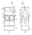
- line 12 is a total with 14 designated cleaning unit inserted a prefilter 18 in the form of a fine dust filter, one out of eight Bulk catalysts 20 (Fig. 2, 3) formed catalyst unit 22 and a fan 24 with a drive motor 26 includes.
- the cleaning unit 14 is in that of ventilation Plants made known modular design, in which the successive, dimensionally stable in the direction of flow Components forming an airtight seal Join the flow channel together, as shown in FIGS. 2 and 3 is shown.
- the pre-filter 18 protects the catalytic converter from atmospheric Dust that can be contained in the exhaust air.
- the bulk material catalysts 20 consist of a stainless steel frame 28 (Fig. 10), the one with the frame width Distance between two parallel, made of stainless steel wire mesh formed grid 30 and 32, between which included the pourable catalyst material is.
- FIGS. 2 and 3 are total four groups 34a, 34b, 34c and 34d of two bulk catalysts each 20 provided, the two Bulk catalysts 20 of each group in the flow direction of the flow channel each other, roughly V-shaped in plan, approach.
- Two groups 34a and 34b are side by side and vertically above these two other groups 34c and 34d.
- the frame 28 of the bulk catalyst 20 is in each case for support on the flow channel enclosing housing 36 of the catalyst unit 22 a Contact shoulder 38 on a generally designated 40 Assigned frame made of a stainless steel hollow profile.
- these frames 40 each in the horizontal direction adjacent groups 34a and 34b or 34c and 34d on one ) crossing the flow channel in the vertical direction Support 42 connected; everyone at the downstream end Group, the two frames 40 are each vertically one above the other arranged groups 34a and 34c or 34b and 34d connected to two further vertical supports 44 and 46.
- each bulk catalyst 20 and each of them associated contact shoulder 38 is a circumferential, frame-like Seal 48 arranged.
- a clamping screw assigned to each clamping bracket 50 ) 52 which in an associated threaded piece 54 on the frame 40th can be screwed, the frame 28 of the bulk catalyst 20 stretched against the frame 40 while doing so the seal 48 becomes firm between the two frames 28 and 40 trapped.
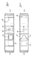
- the catalyst unit 22 ' is in this variant with a single group of two V-shaped bulk catalysts 20 which do not occupy the entire height of the flow channel, which is why the space 60 visible in FIG Bulk catalysts 20 is closed to the entire To guide air flow over the bulk catalyst 20.
- FIG. 6 A system with a circuit is shown schematically in FIG. 6 shown, with this variant as a further assembly a cooler serving as a cooler 62 with a droplet separator is included in the flow channel, which is also in 7 and 8 is shown.
- FIG. 13 shows the use of the catalyst according to the invention for venting an H 2 O 2 tank 64.
- the tank 64 is filled from a tanker vehicle 68 via a filler neck 66.
- the air escaping from the tank and containing H 2 O 2 is discharged via a line 12 ', in which a cleaning unit 14' is included, which comprises a pre-filter 18 'for protecting the catalytic converter and a catalytic converter unit 22' which is equipped with bulk catalysts 20 is provided as described above.
Landscapes
- Chemical & Material Sciences (AREA)
- Engineering & Computer Science (AREA)
- Environmental & Geological Engineering (AREA)
- Organic Chemistry (AREA)
- Chemical Kinetics & Catalysis (AREA)
- Water Supply & Treatment (AREA)
- Hydrology & Water Resources (AREA)
- Life Sciences & Earth Sciences (AREA)
- Health & Medical Sciences (AREA)
- Biomedical Technology (AREA)
- Analytical Chemistry (AREA)
- General Chemical & Material Sciences (AREA)
- Oil, Petroleum & Natural Gas (AREA)
- Materials Engineering (AREA)
- Catalysts (AREA)
Description
- Fig. 1
- eine schematische Darstellung einer Anlage zur katalytischen Reinigung waserstoffperoxidhaltiger Abluft einer Verpackungsmaschine mit Fortluftführung,
- Fig. 2
- eine schematische Seitenansicht der Reinigungseinheit dieser Anlage,
- Fig. 3
- eine schematische Draufsicht auf die Reinigungseinheit,
- Fig. 4
- eine der Fig. 2 ähnliche Seitenansicht einer anderen Ausführungsform der Reinigungeinheit,
- Fig. 5
- eine Draufsicht zu Fig. 4,
- Fig. 6
- eine der Fig. 1 ähnliche Darstellung einer Anlage zur katalytischen Reinigung waserstoffperoxidhaltiger Abluft einer Verpackungsmaschine mit Kreislaufführung,
- Fig. 7
- eine schematische Seitenansicht der Reinigungseinheit der in Fig. 6 gezeigten Anlage,
- Fig. 8
- eine Draufsicht zu Fig. 7,
- Fig. 9
- eine schematische Darstellung der in Fig. 2 gezeigten Anordnung der zwei untere Gruppen bildenden Schüttgutkatalysatoren,
- Fig. 10
- einen Schnitt nach der Linie B-B in Fig. 9,
- Fig. 11
- eine Ansicht in Richtung des Pfeils A in Fig. 9,
- Fig. 12
- einen Darstellung in vergrößertem Maßstab des Details X in Fig. 11 und
- Fig. 13
- eine schematische Darstellung einer Entlüftung für einen Wasserstoffperoxidtank.
Claims (10)
- Verwendung eines Katalysators (20), bei welchem ein hydrophobes Trägermaterial mit einer Oberflächenschicht aus katalytisch wirksamem Material versehen ist, das aus einer Gruppe ausgewählt wird, die Mangan-, Eisen- und Kupferoxid umfasst, zur Zersetzung von in einem Gasstrom mitgeführtem Wasserstoffperoxid.
- Verwendung nach Anspruch 1, dadurch gekennzeichnet, daß als Trägermaterial ein Zeolith eingesetzt wird.
- Verwendung nach Anspruch 2, dadurch gekennzeichnet, daß als Trägermaterial ein Zeolith eingesetzt wird, dessen SiO2/Al2O3-Verhältnis größer als 40 ist.
- Verwendung nach einem der Ansprüche 2 oder 3, dadurch gekennzeichnet, daß ein Trägermaterial eingesetzt wird, das aus einem extrudierten, durch einen hydrophoben Binder gebundenen, pulverförmigen Zeolithmaterial besteht, das in schüttfähige Stücke zerkleinert ist.
- Verwendung nach Anspruch 1, dadurch gekennzeichnet, daß ein Trägermaterialeingesetzt wird, das aus einem verschlungenen Draht auf Nickelbasis besteht.
- Verwendung nach Anspruch 5, dadurch gekennzeichnet, daß ein Trägermaterial eingesetzt wird, das aus schüttfähigen Drahtformlingen besteht.
- Verwendung nach Anspruch 6, dadurch gekennzeichnet, daß ein Trägermaterial eingesetzt wird, das aus Drahtgestrickformlingen besteht.
- Anlage zur Befreiung eines Gasstroms von mitgeführtem Wasserstoffperoxid unter Anwendung des nach einem der Ansprüche 1 bis 7 verwendeten Katalysators, daß in einem Gasführungskanal in Strömungsrichtung aufeinanderfolgend ein Feinstaubvorfilter (18), eine den Katalysator in Form eines Schüttgutkatalysators (20) enthaltende Einheit (22) und ein Ventilator (24) angeordnet sind.
- Anlage nach Anspruch 8, dadurch gekennzeichnet, daß der Schüttgutkatalysator (20) eineh seinen Durchströmquerschnitt umgrenzenden Rahmen (28) aufweist, sowie zwei in Strömungsrichtung mit Abstand voneinander angeordnete, mit dem Rahmen (28) verbundene, den Durchströmquerschnitt ausfüllende Gitterelemente (30, 32), daß der Raum zwischen dem Rahmen (28) und den beiden Gitterelementen (30, 32) mit schüttfähigen Katalysatorelementen ausgefüllt ist, daß der Rahmen (28) durch Klemmbügel (50) gegen eine am Gasführungskanal angeordnete und dem Rahmen zugeordnete Anlageschulter (38) spannbar ist, und daß zwischen dem Rahmen (28) und der Anlageschulter (38) eine umlaufende Dichtung (48) angeordnet ist, wobei der Rahmen (28), die Gitterelemente (30, 32), die Anlageschulter (38) und die Klemmbügel (50) aus einem korrosionsbeständigen Metall bestehen.
- Anlage nach Anspruch 9, dadurch gekennzeichnet, daß als korrosionsbeständiges Metall wahlweise Edelstahl und/oder meerwasserbeständiges Aluminium verwendet ist.
Applications Claiming Priority (2)
| Application Number | Priority Date | Filing Date | Title |
|---|---|---|---|
| DE19723914 | 1997-06-06 | ||
| DE19723914A DE19723914A1 (de) | 1997-06-06 | 1997-06-06 | Katalysator zur Zersetzung von in einem Strömungsmittel mitgeführtem Wasserstoffperoxid und Anlage zur Andwendung des Katalysators |
Publications (2)
| Publication Number | Publication Date |
|---|---|
| EP0882492A1 EP0882492A1 (de) | 1998-12-09 |
| EP0882492B1 true EP0882492B1 (de) | 2004-10-06 |
Family
ID=7831694
Family Applications (1)
| Application Number | Title | Priority Date | Filing Date |
|---|---|---|---|
| EP98106287A Expired - Lifetime EP0882492B1 (de) | 1997-06-06 | 1998-04-06 | Katalysator zur Zersetzung von in einem Fluid mitgeführtem Wasserstoffperoxid und Anlage zur Anwendung des Katalysators |
Country Status (4)
| Country | Link |
|---|---|
| EP (1) | EP0882492B1 (de) |
| AT (1) | ATE278453T1 (de) |
| DE (2) | DE19723914A1 (de) |
| ES (1) | ES2232897T3 (de) |
Cited By (1)
| Publication number | Priority date | Publication date | Assignee | Title |
|---|---|---|---|---|
| EP4552731A1 (de) * | 2023-11-10 | 2025-05-14 | SKAN Deutschland GmbH | Luftreinigungsvorrichtung, containment und dessen verwendung |
Families Citing this family (5)
| Publication number | Priority date | Publication date | Assignee | Title |
|---|---|---|---|---|
| DE19903649A1 (de) * | 1999-01-29 | 2000-08-10 | Degussa | Verfahren zur Gewinnung von Trinkwasser |
| GB2367016A (en) | 2000-08-04 | 2002-03-27 | Microflow Ltd | Apparatus for removing sterilant from a sterilant containing atmosphere |
| KR100414360B1 (ko) * | 2002-11-08 | 2004-01-16 | 주식회사 휴먼메디텍 | 플라즈마 처리기가 부착된 멸균장치 및 멸균방법 |
| WO2016165033A1 (de) | 2015-04-16 | 2016-10-20 | Skan Ag | Katalysatoreinheit zur aufspaltung eines für einen dekontaminations- prozess in ein containment eingebrachten dekontaminationsmittels |
| EP3283194A1 (de) | 2015-04-16 | 2018-02-21 | Skan Ag | Katalysatoreinheit zur aufspaltung eines für einen dekontaminationsprozess in ein containment eingebrachten dekontaminationsmittels |
Family Cites Families (4)
| Publication number | Priority date | Publication date | Assignee | Title |
|---|---|---|---|---|
| IT1179369B (it) * | 1984-05-15 | 1987-09-16 | Ital Idee Srl | Gruppo filtrante multiplo, particolarmente per impianti di aerazione e condizionamento per autoveicoli e ambienti chiusi, munito di mezzi di controllo dell'efficienza |
| US4969936A (en) * | 1989-12-26 | 1990-11-13 | Westates Carbon | Filtration apparatus |
| DE4333328A1 (de) * | 1992-10-07 | 1994-04-14 | Basf Ag | Katalytisches Verfahren zur kontrollierten Zersetzung von Peroxiden |
| DE4432623A1 (de) * | 1994-09-14 | 1996-03-21 | Huels Chemische Werke Ag | Verfahren zur Bleichung von wäßrigen Tensidlösungen |
-
1997
- 1997-06-06 DE DE19723914A patent/DE19723914A1/de not_active Withdrawn
-
1998
- 1998-04-06 AT AT98106287T patent/ATE278453T1/de not_active IP Right Cessation
- 1998-04-06 EP EP98106287A patent/EP0882492B1/de not_active Expired - Lifetime
- 1998-04-06 ES ES98106287T patent/ES2232897T3/es not_active Expired - Lifetime
- 1998-04-06 DE DE59812062T patent/DE59812062D1/de not_active Expired - Lifetime
Cited By (1)
| Publication number | Priority date | Publication date | Assignee | Title |
|---|---|---|---|---|
| EP4552731A1 (de) * | 2023-11-10 | 2025-05-14 | SKAN Deutschland GmbH | Luftreinigungsvorrichtung, containment und dessen verwendung |
Also Published As
| Publication number | Publication date |
|---|---|
| DE59812062D1 (de) | 2004-11-11 |
| EP0882492A1 (de) | 1998-12-09 |
| ATE278453T1 (de) | 2004-10-15 |
| ES2232897T3 (es) | 2005-06-01 |
| DE19723914A1 (de) | 1998-12-10 |
Similar Documents
| Publication | Publication Date | Title |
|---|---|---|
| DE69430451T2 (de) | Vorrichtung zur Durchführung eines Gas-Flüssigkeitskontaktes | |
| DE60114637T2 (de) | System und verfahren zur kohlendioxidabsorption | |
| DE2361636A1 (de) | Venturi-vorrichtung | |
| EP0882492B1 (de) | Katalysator zur Zersetzung von in einem Fluid mitgeführtem Wasserstoffperoxid und Anlage zur Anwendung des Katalysators | |
| DE2649180A1 (de) | Reinigungsvorrichtung zum reinigen eines loesliche verbindungen enthaltenden gases | |
| DE2130983A1 (de) | Verfahren zur Reinigung von Gasgemischen,die als Verunreinigungen insbesondere Kohlenmonoxyd enthalten | |
| DE3344571C2 (de) | Sorptionsanlage zum Reinigen von Industrieabgasen | |
| DE68914596T2 (de) | Methode zur Gas-Flüssig-Kontaktierung. | |
| DE19526980A1 (de) | Verfahren und eine Vorrichtung zur Reinigung von Luft | |
| DE2355368A1 (de) | Vorrichtung zur gasreinigung | |
| CH678371A5 (de) | ||
| AT392219B (de) | Einrichtung zur behandlung von gasen | |
| DE3715263C2 (de) | ||
| DE822085C (de) | Vorrichtung zur gleichmaessigen Verteilung von Fluessigkeiten in Fuellkoerpersaeulen | |
| DE3600462C2 (de) | ||
| DE3628858A1 (de) | Verfahren und vorrichtung zur reinigung von mit toxischen gasen belasteter luft | |
| EP0684151A1 (de) | Verfahren und Vorrichtung zur Frischluft-Neutralisation für Klimaanlagen | |
| DE19827673A1 (de) | Biologischer Luftreiniger | |
| DE2157831B2 (de) | Vorrichtung zum entfernen von schwefeloxiden aus abgasen | |
| DE3341318A1 (de) | Nassabscheider sowie verfahren zur nassabscheidung von in gasen dispergierten schwebestoffen | |
| DE2058108A1 (de) | Verfahren zur Beseitigung von Stickoxyden aus Abgasen und Vorrichtung fuer dieses | |
| EP0696886B1 (de) | Vorrichtung zum lösen von gasen in flüssigkeiten | |
| DE3644179A1 (de) | Filtereinrichtung zum reinigen von gasstroemen | |
| DE2116996A1 (de) | Verfahren und Vorrichtung zum Ent fernen von in einem Gas enthaltenen schädlichen Verunreinigungssubstanzen | |
| DE3803454A1 (de) | Absorbat - transportbehaelter |
Legal Events
| Date | Code | Title | Description |
|---|---|---|---|
| PUAI | Public reference made under article 153(3) epc to a published international application that has entered the european phase |
Free format text: ORIGINAL CODE: 0009012 |
|
| AK | Designated contracting states |
Kind code of ref document: A1 Designated state(s): AT BE CH DE ES FR GB IT LI NL |
|
| AX | Request for extension of the european patent |
Free format text: AL;LT;LV;MK;RO;SI |
|
| 17P | Request for examination filed |
Effective date: 19990608 |
|
| AKX | Designation fees paid |
Free format text: AT BE CH DE ES FR GB IT LI NL |
|
| 17Q | First examination report despatched |
Effective date: 20021017 |
|
| GRAP | Despatch of communication of intention to grant a patent |
Free format text: ORIGINAL CODE: EPIDOSNIGR1 |
|
| GRAS | Grant fee paid |
Free format text: ORIGINAL CODE: EPIDOSNIGR3 |
|
| GRAA | (expected) grant |
Free format text: ORIGINAL CODE: 0009210 |
|
| AK | Designated contracting states |
Kind code of ref document: B1 Designated state(s): AT BE CH DE ES FR GB IT LI NL |
|
| REG | Reference to a national code |
Ref country code: GB Ref legal event code: FG4D Free format text: NOT ENGLISH |
|
| REG | Reference to a national code |
Ref country code: CH Ref legal event code: EP |
|
| BECA | Be: change of holder's address |
Owner name: *BERLINERLUFT KLIMATECHNIK G.M.B.H.IN DER KOLLING, Effective date: 20041006 |
|
| BECH | Be: change of holder |
Owner name: *BERLINERLUFT KLIMATECHNIK G.M.B.H. Effective date: 20041006 |
|
| REF | Corresponds to: |
Ref document number: 59812062 Country of ref document: DE Date of ref document: 20041111 Kind code of ref document: P |
|
| RAP2 | Party data changed (patent owner data changed or rights of a patent transferred) |
Owner name: BERLINERLUFT KLIMATECHNIK GMBH |
|
| NLT2 | Nl: modifications (of names), taken from the european patent patent bulletin |
Owner name: BERLINERLUFT KLIMATECHNIK GMBH |
|
| GBT | Gb: translation of ep patent filed (gb section 77(6)(a)/1977) |
Effective date: 20050116 |
|
| REG | Reference to a national code |
Ref country code: GB Ref legal event code: 732E |
|
| PGFP | Annual fee paid to national office [announced via postgrant information from national office to epo] |
Ref country code: GB Payment date: 20050322 Year of fee payment: 8 Ref country code: AT Payment date: 20050322 Year of fee payment: 8 |
|
| PGFP | Annual fee paid to national office [announced via postgrant information from national office to epo] |
Ref country code: NL Payment date: 20050418 Year of fee payment: 8 |
|
| REG | Reference to a national code |
Ref country code: ES Ref legal event code: FG2A Ref document number: 2232897 Country of ref document: ES Kind code of ref document: T3 |
|
| PLBE | No opposition filed within time limit |
Free format text: ORIGINAL CODE: 0009261 |
|
| STAA | Information on the status of an ep patent application or granted ep patent |
Free format text: STATUS: NO OPPOSITION FILED WITHIN TIME LIMIT |
|
| ET | Fr: translation filed | ||
| 26N | No opposition filed |
Effective date: 20050707 |
|
| PG25 | Lapsed in a contracting state [announced via postgrant information from national office to epo] |
Ref country code: GB Free format text: LAPSE BECAUSE OF NON-PAYMENT OF DUE FEES Effective date: 20060406 Ref country code: AT Free format text: LAPSE BECAUSE OF NON-PAYMENT OF DUE FEES Effective date: 20060406 |
|
| PG25 | Lapsed in a contracting state [announced via postgrant information from national office to epo] |
Ref country code: NL Free format text: LAPSE BECAUSE OF NON-PAYMENT OF DUE FEES Effective date: 20061101 |
|
| GBPC | Gb: european patent ceased through non-payment of renewal fee |
Effective date: 20060406 |
|
| NLV4 | Nl: lapsed or anulled due to non-payment of the annual fee |
Effective date: 20061101 |
|
| PGFP | Annual fee paid to national office [announced via postgrant information from national office to epo] |
Ref country code: BE Payment date: 20070419 Year of fee payment: 10 |
|
| PGFP | Annual fee paid to national office [announced via postgrant information from national office to epo] |
Ref country code: ES Payment date: 20080424 Year of fee payment: 11 |
|
| PGFP | Annual fee paid to national office [announced via postgrant information from national office to epo] |
Ref country code: IT Payment date: 20080426 Year of fee payment: 11 |
|
| BERE | Be: lapsed |
Owner name: *BERLINERLUFT KLIMATECHNIK G.M.B.H. Effective date: 20080430 |
|
| PGFP | Annual fee paid to national office [announced via postgrant information from national office to epo] |
Ref country code: FR Payment date: 20080404 Year of fee payment: 11 |
|
| PG25 | Lapsed in a contracting state [announced via postgrant information from national office to epo] |
Ref country code: BE Free format text: LAPSE BECAUSE OF NON-PAYMENT OF DUE FEES Effective date: 20080430 |
|
| REG | Reference to a national code |
Ref country code: FR Ref legal event code: ST Effective date: 20091231 |
|
| PG25 | Lapsed in a contracting state [announced via postgrant information from national office to epo] |
Ref country code: FR Free format text: LAPSE BECAUSE OF NON-PAYMENT OF DUE FEES Effective date: 20091222 |
|
| REG | Reference to a national code |
Ref country code: ES Ref legal event code: FD2A Effective date: 20090407 |
|
| PG25 | Lapsed in a contracting state [announced via postgrant information from national office to epo] |
Ref country code: ES Free format text: LAPSE BECAUSE OF NON-PAYMENT OF DUE FEES Effective date: 20090407 |
|
| PG25 | Lapsed in a contracting state [announced via postgrant information from national office to epo] |
Ref country code: IT Free format text: LAPSE BECAUSE OF NON-PAYMENT OF DUE FEES Effective date: 20090406 |
|
| PGFP | Annual fee paid to national office [announced via postgrant information from national office to epo] |
Ref country code: CH Payment date: 20110221 Year of fee payment: 14 |
|
| PGFP | Annual fee paid to national office [announced via postgrant information from national office to epo] |
Ref country code: DE Payment date: 20110505 Year of fee payment: 14 |
|
| REG | Reference to a national code |
Ref country code: CH Ref legal event code: PL |
|
| PG25 | Lapsed in a contracting state [announced via postgrant information from national office to epo] |
Ref country code: LI Free format text: LAPSE BECAUSE OF NON-PAYMENT OF DUE FEES Effective date: 20120430 Ref country code: CH Free format text: LAPSE BECAUSE OF NON-PAYMENT OF DUE FEES Effective date: 20120430 |
|
| REG | Reference to a national code |
Ref country code: DE Ref legal event code: R119 Ref document number: 59812062 Country of ref document: DE Effective date: 20121101 |
|
| PG25 | Lapsed in a contracting state [announced via postgrant information from national office to epo] |
Ref country code: DE Free format text: LAPSE BECAUSE OF NON-PAYMENT OF DUE FEES Effective date: 20121101 |