EP0882527A2 - Verfahren und Anlage zur Übergabe eines Drahtbundes von der Bundbildestation eines Kühltransportes auf einen C-Haken einer Hakenbahn - Google Patents
Verfahren und Anlage zur Übergabe eines Drahtbundes von der Bundbildestation eines Kühltransportes auf einen C-Haken einer Hakenbahn Download PDFInfo
- Publication number
- EP0882527A2 EP0882527A2 EP98107000A EP98107000A EP0882527A2 EP 0882527 A2 EP0882527 A2 EP 0882527A2 EP 98107000 A EP98107000 A EP 98107000A EP 98107000 A EP98107000 A EP 98107000A EP 0882527 A2 EP0882527 A2 EP 0882527A2
- Authority
- EP
- European Patent Office
- Prior art keywords
- hook
- bundle
- track
- wire
- chamber
- Prior art date
- Legal status (The legal status is an assumption and is not a legal conclusion. Google has not performed a legal analysis and makes no representation as to the accuracy of the status listed.)
- Withdrawn
Links
Images


Classifications
-
- B—PERFORMING OPERATIONS; TRANSPORTING
- B66—HOISTING; LIFTING; HAULING
- B66C—CRANES; LOAD-ENGAGING ELEMENTS OR DEVICES FOR CRANES, CAPSTANS, WINCHES, OR TACKLES
- B66C1/00—Load-engaging elements or devices attached to lifting or lowering gear of cranes or adapted for connection therewith for transmitting lifting forces to articles or groups of articles
- B66C1/10—Load-engaging elements or devices attached to lifting or lowering gear of cranes or adapted for connection therewith for transmitting lifting forces to articles or groups of articles by mechanical means
- B66C1/22—Rigid members, e.g. L-shaped members, with parts engaging the under surface of the loads; Crane hooks
- B66C1/24—Single members engaging the loads from one side only
-
- B—PERFORMING OPERATIONS; TRANSPORTING
- B21—MECHANICAL METAL-WORKING WITHOUT ESSENTIALLY REMOVING MATERIAL; PUNCHING METAL
- B21C—MANUFACTURE OF METAL SHEETS, WIRE, RODS, TUBES, PROFILES OR LIKE SEMI-MANUFACTURED PRODUCTS OTHERWISE THAN BY ROLLING; AUXILIARY OPERATIONS USED IN CONNECTION WITH METAL-WORKING WITHOUT ESSENTIALLY REMOVING MATERIAL
- B21C47/00—Winding-up, coiling or winding-off metal wire, metal band or other flexible metal material characterised by features relevant to metal processing only
- B21C47/24—Transferring coils to or from winding apparatus or to or from operative position therein; Preventing uncoiling during transfer
- B21C47/242—Devices for swinging the coil from horizontal to vertical, or vice versa
Definitions
- the invention relates to a method and a plant for Handover of a wire bundle from the bundle formation chamber Bundling station of a refrigerated transport on a C-hook hook track equipped with running tracks.
- Transport systems for example with monorails and with Possibility to carry out transfer operations are known. This gives you the opportunity to transfer from Transport units to other transport circles, branch lines or lifting stations. This also includes the controlled Passing through switches.
- Such conveyor systems have current state-of-the-art tasks fulfill, for example distributing, sorting or buffering, and this with comparatively high funding.
- following wire lines too fully automatic wire coil forming stations known.
- the object is achieved with the invention in one Method of the type mentioned in the preamble of claim 1 the invention in that the coil of wire directly on the vertically pivoted hook is passed.
- the Bundle station of comparatively high maintenance and occasionally also elements of the bundle tilt or prone to failure Relief devices relieved, making a trouble-free High throughput operation is guaranteed.
- An embodiment of the method according to the invention provides before that a hook to be loaded after opening one of the The bundle station assigned to the track area below Use of a gripper device taken from this and the horizontal mandrel of the hook during transport pivoted into the vertical position, raised and then the individual wire turns or the coil of wire on the Arbor can be dropped, followed by the loaded hook lowered with the arbor into the horizontal position pivoted back into the running track of the hook track inserted, the track area closed, the hook transported away in the hook track and a next one to be loaded Hook brought up and the loading process is repeated.
- the lifting means for raising / lowering the Hook in the gripper device is dimensioned so that the Tip of the arbor tight in the raised position is below the inlet level of the refrigerated transport, whereby when loading a hook wire turns for one subsequent hooks are held back by separating fingers.
- An embodiment of the method further provides that the Loading process with slow running wire lines with comparatively low production output on one Bundle formation station carried out without a plate and without a hat becomes. This makes the process or the system significant simplified.
- the gripper device is lifted and can be lowered and moved longitudinally in a frame. This results in the possibility that the individual process steps and motion sequences independently to realize each other and thereby in very run clearly and functionally uncomplicated allow.
- a further embodiment results for the method in that individually falling on the arbor Wire windings, or a complete wire bundle, on Hook backs are caught by side support strips. This ensures that after opening the separation fingers Wire windings, as is common with simple systems, directly up to fall on the widened hook back and there from the widened edition to be caught. Then the loaded hook after it is lowered and swung back, pushed back into the hook track. After the Hook is moved, a new empty hook is loaded accepted.
- the measure can be used to advantage, that to produce an accurate wire bundle in the A hat as well as a liftable and lowerable one Flange plate is used and the tip of the arbor at raised hook wearing the hat while on the collar plate Wire windings collected to form a covenant and this from the flange plate gently on the prepared hook back discontinued and then lowered the collar plate and the loaded hooks brought back to the hook track and a new one Hook is fetched. After the second hook is loaded, and the carriage has been moved against the direction of the hook path, after inserting this hook into the hook path Empty hook moved to the storage position.
- flange plate and side empty hooks are used for turning, lifting and Moving hooks of two gripper devices onto one in Movable carriage used in the direction of the hook track, with an empty hook in the middle of the axis of the bundle chamber kept ready for loading and left or right of the If necessary, the bundle forming chamber can be removed from the hook track or reintroduced, with one on the middle of the Bundle chamber standing hook lowered after loading and the carriage with the gripper devices has an empty hook Position of the Bundestag chamber moves, the one in it raised and loaded and then lowered and with the Gripper device is moved back to the hook path, after which the empty hook on the side, ready for lifting is brought up into the Bundsentecro.
- the collar plate according to the federal government on the hooks as far is lowered that a standing empty, vertical Standing hook moved sideways to the middle of the bundle chamber can be, or that optionally the collar plate to the rear is moved and the lowering stroke is not increased got to.
- the bundling chamber of the bundling station of a refrigerated transport a C-hook of a hook track equipped with running tracks is essentially characterized in that the hook track Means for opening and closing a track area and in cooperation with it a gripper device with a this receiving frame with a drive for pivoting the Hook from a horizontal position to a vertical position and vice versa, as well as with a drive for lifting and lowering, and finally with a drive for longitudinal movement of a Has hook.
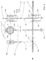
- FIG. 1 shows a system for transferring a coil of wire (30) from a bundle formation chamber (3) of the bundle formation station (2) Cooling transport (1) on a C-hook (16, 16a, 16b) with one Rails equipped hook track (6), especially for slow running wire lines with comparatively less Production without a collar and without a hat.
- Cooling transport (1) on a C-hook (16, 16a, 16b) with one Rails equipped hook track (6), especially for slow running wire lines with comparatively less Production without a collar and without a hat.
- separating fingers 11
- the figure shows that the Wire bundle directly on the vertical mandrel (17) is built up by collecting the turns (5).
- the too loading (16b), which is initially still empty, is removed from the Hook path (6) after opening the lower one Track area (7) from the gripper system (15).
- This gripper system (15) is equipped with means to Turn the hook (16b) to the vertical position, as in Area of the fret forming station (2) is shown.
- the bundle chamber (3) can with swivel axes (13) for Chamber halves (4, Fig. 3) are designed to extend of the loaded hook (16a) can be opened. Right away are located on the back of each hook (16) Support strips or a support plate (19) on which the to be formed collar (30), Fig. 2, rests.
- Means (9) in the form of a drive for lifting and lowering the Hook provided. In total, hooks (16) can be inserted through the individual device elements raised, lowered and longitudinal process.
- the means (9) are preferred with Elements for lifting, lowering and longitudinal movement in one separate frame added, but for reasons of Clarity is not shown.
- the stroke of the lifting and lowering device (9) is such that the tip of the mandrel (17) in the raised position stands just below the inlet level of the refrigerated transport (1).
- a separate drive (10) is provided for the transverse movement. After the hook (16a) is loaded with a collar, it becomes lowered with the device (9), with the device (10) Move to the side, raised and into the track area (7) inserted and with the hook track after closing the Move the track area (7) in the transport direction.
- Figure 2 shows a system for slow-running wire lines with low production, but with flange plate (21) and hat (20) in the shortened bundle chamber (3) of the Bundle station (2).
- the hat (20) for the creation of a particularly good, accurate fret image in the Bundsentehunt (3).
- Figure 3 shows a system for wire lines with higher Rolling performance, but without hat and flange plate.
- the bundle chamber (3) shows an open one on the left Chamber half (4) on one of the swivel axes (13) is articulated.
- the bundle chamber (3) can be opened wide so that a hook (16), as with the capital letters A and B. indicated schematically, from the viewer's side, so can be retracted or extended from the front, with or without a collar can.
- the system is designed according to Figure 4.
- she excels especially for keeping a stock side empty hook (16b).
- the facilities (10, 15, 23, 24) for rotating, lifting and moving a hook (16a - 16e) are duplicated and on one in the direction of the Hook track (6) arranged movable carriage.
- the hook track (6) can be an empty hook Save (16c). Hooks (16b, 16e) removed from the hook track (6) and reinserted will.
- the hook transfers (14a, 14b) are provided for this. These transfers (14a, 14b) are also to the hook track (6) cross-movable hook track lines (18a, 18b).
- (23) and (24) are drives for the intermediate transport of empty or loaded hooks (16b, 16d or 16e) across Hook track (6) along the cross transports (27 - 29) featured.
- the drive (10) which is also double can exist, serves as a kind of ferry traffic between the Cross transports (27 - 29) from right to left and vice versa.
- One of the hooks can be used with the gripper device (15) (16a - 16e) from the horizontal position to the vertical Position can be rotated. This system lowers the Collar plate, not shown in the top view, after delivery of the Federal on the hooks so far that the empty one vertically standing second hooks on the side on the middle of the fret station (3) can be driven. If then according to Fig. 6 Can be moved backwards, the Lowering stroke for the hook (16a or 16b) cannot be increased.
- Figure 6 corresponds to that of Figure 4.
- the collar plate (21) in addition to the drive (22) for lifting and lowering an additional one Drive (23) for wide lateral movement, whereby the Empty hooks first in a horizontal position under the The bundle formation chamber (3) of the bundle formation station (2) can be moved can and only in the position reached in the vertical position is swung open.
- the system is extremely functional, uncomplicated, functionally safe and trouble-free available and solves in optimally the task at the beginning.
Landscapes
- Engineering & Computer Science (AREA)
- Mechanical Engineering (AREA)
- Winding, Rewinding, Material Storage Devices (AREA)
- Intermediate Stations On Conveyors (AREA)
Abstract
Description
- Fig. 1
- in Seitenansicht eine Anlage zur Übergabe eines Drahtbundes von einer Bundbildekammer der Bundbildestation eines Kühltransportes auf einen C-Haken einer mit Laufschienen ausgestatteten Hakenbahn,
- Fig. 2
- eine Anlage gemäß Fig. 1 jedoch mit Hut und Bundplatte,
- Fig. 3
- eine andere Ausgestaltung der Bundbildekammer mit schwenkbaren Kammerhälften, ebenfalls in Seitenansicht,
- Fig. 4
- eine Draufsicht auf die Anlage mit Bundbildekammer und Quertransporten sowie Abstellpositionen für Leerhaken und beladene Haken,
- Fig. 5
- eine Anlage mit Bundbildekammer unter Verwendung einer senk- und hebbaren sowie zur Seite herausfahrbaren Bundplatte, ebenso in Seitenansicht,
- Fig. 6
- in Draufsicht eine Anlage für höhere Walzleistung mit Hut und Bundplatte, wobei diese bei kleinerem Vertikalhub vor- und zurückfahrbar ist.
Claims (15)
- Verfahren zur Übergabe eines Drahtbundes (30) von der Bundbildekammer (3) einer Bundbildestation (2) eines Kühltransportes (1) auf einen C-Haken (16, 16a, 16b) einer mit Laufschienen ausgestatteten Hakenbahn (6), dadurch gekennzeichnet, dass der Drahtbund (30) unmittelbar auf die vertikal geschwenkten Haken (16a) übergeben wird.
- Verfahren nach Anspruch 1, dadurch gekennzeichnet, dass ein zu beladender Haken (16, 16a - 16e) nach Öffnen eines der Bundbildestation (2) zugeordneten Laufschienenbereiches (7) unter Verwendung einer Greifereinrichtung (15) von dieser übernommen und dabei der beim Transport horizontale Aufnahmedorn (17) des Hakens (16) in die vertikale Position geschwenkt, angehoben und sodann die einzelnen Drahtwindungen (5) oder der Drahtbund (30) auf den Aufnahmedorn (17) fallen gelassen werden, worauf der beladene Haken (16) abgesenkt, mit dem Aufnahmedorn (17) in die horizontale Position zurückgeschwenkt, in die Laufschiene der Hakenbahn (6) eingeschoben, der Laufschienenbereich (7) geschlossen, der Haken (16a) in der Hakenbahn (6) abtransportiert und ein nächster zu beladender Haken (16b) herangeführt und mit diesem das Beladungsverfahren wiederholt wird.
- Verfahren nach Anspruch 1 oder 2, dadurch gekennzeichnet, dass der Hub von Mitteln (9) zum Heben/Senken des Hakens (16) in der Greifereinrichtung (15) so bemessen ist, dass die Spitze des Aufnahmedorns (17) in angehobener Position dicht unterhalb des Einlaufniveaus des Kühltransportes (1) steht, wobei während des Beladens von einem Haken (16a) Drahtwindungen (5) für einen nachfolgenden Haken (16b) durch Trennfinger (11) zurückgehalten werden.
- Verfahren nach einem oder mehreren der Ansprüche 1 bis 3, dadurch gekennzeichnet, dass der Beladungsvorgang bei langsam laufenden Drahtstraßen mit vergleichsweise geringer Produktionsleistung an einer Bundbildestation (2) ohne Bundplatte (21) und ohne Hut (20) durchgeführt wird.
- Verfahren nach einem oder mehreren der Ansprüche 1 bis 4, dadurch gekennzeichnet, dass die Greifereinrichtung (15) heb- und senkbar sowie längsverfahrbar in einem Rahmen aufgenommen wird.
- Verfahren nach einem oder mehreren der Ansprüche 1 bis 5, dadurch gekennzeichnet, dass einzeln auf den Aufnahmedorn (17) fallende Drahtwindungen (5) bzw. ein vollständiger Drahtbund (30) am Hakenrücken von seitlichen Auflageleisten (19) aufgefangen werden.
- Verfahren nach einem oder mehreren der Ansprüche 1 bis 6, dadurch gekennzeichnet, dass zur Herstellung eines akkuraten Drahtbundes (30) in der Bundbildekammer (3) ein Hut (20) sowie eine heb- und senkbare Bundplatte (21) verwendet wird und die Spitze des Aufnahmedorns (17) bei angehobenem Haken (16a) den Hut (20) trägt, während auf der Bundplatte (21) Drahtwindungen (5) unter Bildung eines Bundes (30) gesammelt und dieser von der Bundplatte (21) schonend auf dem verbreiterten Hakenrücken abgesetzt und anschließend die Bundplatte (21) abgesenkt und der beladene Haken (16a) zur Hakenbahn (6) zurückgebracht und ein neuer Haken (16b) geholt wird.
- Verfahren nach Anspruch 1, dadurch gekennzeichnet, dass für eine vergleichsweise höhere Bundübergabeleistung zwei Greifereinrichtungen (15) zum Drehen, Heben und Verfahren von Haken (16) auf einem in Laufrichtung der Hakenbahn (6) verfahrbaren Wagen verwendet werden, wobei in Achsmitte der Bundbildekammer (3) jeweils ein Leerhaken (16b) in Beladebereitschaft gehalten und links oder rechts der Bundbildekammer (3) Haken (16) bedarfsweise aus der Hakenbahn (6) entnommen bzw. wieder eingeführt werden, wobei ein auf Mitte der Bundbildekammer (3) stehender Haken (16a) nach dessen Beladung abgesenkt und der Wagen mit den Greifereinrichtungen (15) einen Leerhaken (16c) in Aufnahmestellung der Bundbildekammer (3) verfährt, der darin angehoben und beladen und danach abgesenkt und mit der Greifereinrichtung (15) zur Hakenbahn (6) zurückverfahren wird, wodurch der leere, seitlich in Bereitschaft stehende Haken (16b) zum Anheben in die Bundbildekammer (3) herangebracht wird.
- Verfahren nach Anspruch 8, dadurch gekennzeichnet, dass nach Verfahren des Wagens in Laufrichtung der Hakenbahn (6) und Einfügen in die Hakenbahn (6) der bereitstehende Leerhaken (16b) aufgenommen und nach Beladen des zweiten Hakens (16d) der Wagen entgegen der Hakenbahnlaufrichtung verfahren, in die Hakenbahn (6) eingefügt und ein Leerhaken (16c) in die Speicherposition gefahren sowie ein weiterer Leerhaken (16) von der freien Greifereinrichtung (15) aufgenommen wird.
- Verfahren nach einem oder mehreren der Ansprüche 1 bis 9, dadurch gekennzeichnet, dass bei einer Drahtbundübergabe unter Verwendung von Hut (20) und Bundplatte (21) in der Bundbildekammer (3) entweder die Bundplatte (21) nach Übergabe des Bundes (30a) an den Haken (16) soweit abgesenkt wird, dass ein bereitstehender leerer, vertikalstehender Haken (16b) seitlich auf Mitte Bundbildekammer (3) gefahren werden kann, oder, dass wahlweise die Bundpaltte (21) nach hinten verschoben wird und hierfür der Absenkhub nicht erhöht werden muss.
- Anlage zur Übergabe eines Drahtbundes (30) von einer Bundbildekammer (3) der Bundbildestation (2) eines Kühltransportes (1) auf einen C-Haken (16) einer mit Laufschienen ausgestatteten Hakenbahn (6), insbesondere zur Durchführung des Verfahrens nach den vorhergehenden Ansprüchen, dadurch gekennzeichnet, dass die Hakenbahn (6) Mittel (8) zum Öffnen und Schliessen eines Laufschienenbereiches (7) und im Zusammenwirken damit eine Greifereinrichtung (15) mit einem diese aufnehmenden Rahmen mit einem Antrieb zum Schwenken eines Hakens (16) von einer Horizontalstellung in eine Vertikalstellung und umgekehrt, sowie mit einem Antrieb (9) zum Heben und Senken, und schließlich mit einem Antrieb zum Längsverfahren eines Hakens (16) aufweist.
- Anlage nach Anspruch 11, dadurch gekennzeichnet, dass die Haken (16) am Hakenrücken seitlich vorstehende Auflagen (19) haben, und dass zum Zurückhalten von Windungen (5) des Drahtes für den nachfolgenden Bund (30) Trennfinger (11) vorgesehen sind.
- Anlage nach Anspruch 11 oder 12, dadurch gekennzeichnet, dass in der Bundbildekammer (3) ein Hut (20) und eine heb- und senkbare Bundplatte (21) sowie im Zusammenwirken mit dieser eine optische Überwachung (26) für eine Bundsammellinie (12) vorgesehen sind.
- Anlage nach einem oder mehreren der Ansprüche 11 bis 13, dadurch gekennzeichnet, dass die Bundbildekammer (3) in Schwenkachsen (13) anlenkbare Kammerhälften (4) besitzt, die zum Einfahren eines Hakens (16c) und Ausfahren eines Bundes (30a) öffenbar und während der Ausbildung eines Bundes (30) schließbar sind.
- Anlage nach Anspruch 11, dadurch gekennzeichnet, dass die Einrichtungen (14a, 14b; 15; 18a, 18b; 23, 24) zum Drehen, Heben/Senken, Verfahren des Wagens sowie zur Übergabe an die Hakenbahn (6) zweimal vorhanden sind, und dass Quertransporte (27 - 29) vorgesehen sind, von welchen der mittlere (28) zum Ein- und Ausfahren von Haken (16b, 16c) bzw. von Bund (30a) in und aus der Bundbildekammer (3) bei geöffneten Kammerhälften (4), und der linksseitige (27) zur Bereitstellung eines Leerhakens (16a), und der rechtsseitige (29) als Warteposition für einen fertigen Bund (30b) bzw. als Übergabe (14b) von einem Bund (30c) an die Hakenbahn (6) ausgebildet sind.
Applications Claiming Priority (2)
| Application Number | Priority Date | Filing Date | Title |
|---|---|---|---|
| DE19717769 | 1997-04-26 | ||
| DE19717769A DE19717769A1 (de) | 1997-04-26 | 1997-04-26 | Verfahren und Anlage zur Übergabe eines Drahtbundes von der Bundbildestation eines Kühltransportes auf enen C-Haken einer Hakenbahn |
Publications (2)
| Publication Number | Publication Date |
|---|---|
| EP0882527A2 true EP0882527A2 (de) | 1998-12-09 |
| EP0882527A3 EP0882527A3 (de) | 2001-03-21 |
Family
ID=7827894
Family Applications (1)
| Application Number | Title | Priority Date | Filing Date |
|---|---|---|---|
| EP98107000A Withdrawn EP0882527A3 (de) | 1997-04-26 | 1998-04-17 | Verfahren und Anlage zur Übergabe eines Drahtbundes von der Bundbildestation eines Kühltransportes auf einen C-Haken einer Hakenbahn |
Country Status (4)
| Country | Link |
|---|---|
| US (1) | US6024316A (de) |
| EP (1) | EP0882527A3 (de) |
| JP (1) | JPH1133625A (de) |
| DE (1) | DE19717769A1 (de) |
Cited By (1)
| Publication number | Priority date | Publication date | Assignee | Title |
|---|---|---|---|---|
| CN106881581A (zh) * | 2015-12-16 | 2017-06-23 | 中国二十冶集团有限公司 | 一种用于大盘卷移送装置的安装工具及其使用方法 |
Families Citing this family (3)
| Publication number | Priority date | Publication date | Assignee | Title |
|---|---|---|---|---|
| US10087003B2 (en) * | 2015-09-10 | 2018-10-02 | Primetals Technologies USA LLC | Direct coil transfer system |
| CN108706457B (zh) * | 2018-07-27 | 2023-06-06 | 湖南科技大学 | 一种吊钩摆动智能监控系统及方法 |
| WO2020158380A1 (ja) | 2019-01-30 | 2020-08-06 | 富士フイルム株式会社 | 洗出し装置および洗出し方法 |
Family Cites Families (4)
| Publication number | Priority date | Publication date | Assignee | Title |
|---|---|---|---|---|
| BE759942A (fr) * | 1969-12-08 | 1971-05-17 | Morgan Construction Co | Dispositif pour transferer des bobines de produit cylindrique d'un poste de formation de bobines a un transporteur adjacent |
| US4251037A (en) * | 1979-11-13 | 1981-02-17 | Morgan Construction Company | Coil forming apparatus with axially adjustable mandrels |
| DE3525089C2 (de) * | 1985-07-13 | 1995-09-28 | Schloemann Siemag Ag | Drahtbund-Bildestation |
| DE4106491A1 (de) * | 1991-03-01 | 1992-09-03 | Schloemann Siemag Ag | Anlage mit einem bundbilde- und transportsystem fuer draht oder feinstahl, insbesondere fuer hohe bundgewichte |
-
1997
- 1997-04-26 DE DE19717769A patent/DE19717769A1/de not_active Withdrawn
-
1998
- 1998-04-17 EP EP98107000A patent/EP0882527A3/de not_active Withdrawn
- 1998-04-23 US US09/065,322 patent/US6024316A/en not_active Expired - Fee Related
- 1998-04-24 JP JP10115556A patent/JPH1133625A/ja not_active Withdrawn
Cited By (1)
| Publication number | Priority date | Publication date | Assignee | Title |
|---|---|---|---|---|
| CN106881581A (zh) * | 2015-12-16 | 2017-06-23 | 中国二十冶集团有限公司 | 一种用于大盘卷移送装置的安装工具及其使用方法 |
Also Published As
| Publication number | Publication date |
|---|---|
| DE19717769A1 (de) | 1998-10-29 |
| US6024316A (en) | 2000-02-15 |
| EP0882527A3 (de) | 2001-03-21 |
| JPH1133625A (ja) | 1999-02-09 |
Similar Documents
| Publication | Publication Date | Title |
|---|---|---|
| EP0541744B1 (de) | Verfahren und vorrichtung zum stapeln | |
| DE3502611C2 (de) | ||
| DE69813435T2 (de) | Walzenwechselvorrichtung für Arbeitswalzen oder Zwischenwalzen von Walzgerüsten und Einlagerungsvorrichtung | |
| EP0492226A2 (de) | Verfahren und Anlage zum Auswalzen von Warmbreitband aus stranggegossenen Dünnbrammen | |
| DE3702265C2 (de) | Verfahren und Vorrichtung zum Austausch von Spulen und Hülsen an Vorspinnmaschinen | |
| DE2558964A1 (de) | Vorrichtung zum foerdern von bunden von bandstahl zu einer abwickelstation | |
| EP0566910B1 (de) | Vorrichtung zum Transport von zu Ringen gewickeltem Walzgut im Haspelbereich | |
| EP0882527A2 (de) | Verfahren und Anlage zur Übergabe eines Drahtbundes von der Bundbildestation eines Kühltransportes auf einen C-Haken einer Hakenbahn | |
| DE19505050C2 (de) | Transport- und Umsetzsystem zwischen mindestens einer Vorspinnmaschine und einem nachgeordneten Lager- oder Verarbeitungsbereich | |
| DE102006051540A1 (de) | Verfahren und Herstellungsstation, welche bei der Herstellung eines Fahrzeugluftreifens zur Anwendung gelangen | |
| DE102005027544A1 (de) | Umsetzstation zur Übergabe einer Materialrolle zwischen zwei verschiedenartigen in Förderrichtung aufeinander folgenden Fördermitteln | |
| DE1685830A1 (de) | Maschine zum Herstellen von Kabeln oder Seilen | |
| DE2446707B2 (de) | Foerderer, insbesondere fuer hopfenpflueckmaschinen | |
| EP0855456B1 (de) | Verfahren und Vorrichtung zum Transportieren voller Vorgarnspulen bzw. leerer Vorgarnhülsen | |
| DE2917027A1 (de) | Verfahren und einrichtung zum foerdern von aufeinanderfolgenden heissen wicklungen | |
| DE1452386A1 (de) | Anlage zum Ziehen von Rohren | |
| DE19516473C2 (de) | Verfahren zum Versetzen der Bandanlage eines Absetzgerätes, eines Aufnahmegerätes o. dgl. und Einrichtung zur Durchführung des Verfahrens | |
| DE1452016A1 (de) | Aufstell- und Verschiebevorrichtung fuer Walzstaebe,insbesondere Profile | |
| DE2731559A1 (de) | Stapelvorrichtung fuer profilstaebe aus stahl | |
| DE2810179C2 (de) | Ringsammelstation für Drahtringe | |
| DE3109110A1 (de) | Vorrichtung zur bildung von walzdrahtbunden | |
| DE4130417C2 (de) | Vorrichtung zum Vereinzeln und Verschwenken von Schmalbandbunden | |
| DE2212944B2 (de) | Verfahren und vorrichtung zur bildung von walzdrahtbunden | |
| DE4109201A1 (de) | Vorrichtung zum transportieren und schopfen einer walzader | |
| DE2246132C3 (de) | Vorrichtung zur Weiterleitung von Walzgut am Kühlbettende |
Legal Events
| Date | Code | Title | Description |
|---|---|---|---|
| PUAI | Public reference made under article 153(3) epc to a published international application that has entered the european phase |
Free format text: ORIGINAL CODE: 0009012 |
|
| 17P | Request for examination filed |
Effective date: 19980417 |
|
| AK | Designated contracting states |
Kind code of ref document: A2 Designated state(s): AT DE IT SE |
|
| AX | Request for extension of the european patent |
Free format text: AL;LT;LV;MK;RO;SI |
|
| RAP1 | Party data changed (applicant data changed or rights of an application transferred) |
Owner name: SMS DEMAG AG |
|
| PUAL | Search report despatched |
Free format text: ORIGINAL CODE: 0009013 |
|
| AK | Designated contracting states |
Kind code of ref document: A3 Designated state(s): AT BE CH CY DE DK ES FI FR GB GR IE IT LI LU MC NL PT SE |
|
| AX | Request for extension of the european patent |
Free format text: AL;LT;LV;MK;RO;SI |
|
| AKX | Designation fees paid |
Free format text: AT DE IT SE |
|
| GRAH | Despatch of communication of intention to grant a patent |
Free format text: ORIGINAL CODE: EPIDOS IGRA |
|
| STAA | Information on the status of an ep patent application or granted ep patent |
Free format text: STATUS: THE APPLICATION IS DEEMED TO BE WITHDRAWN |
|
| 18D | Application deemed to be withdrawn |
Effective date: 20030808 |