EP0882531A2 - Dispositif d'usinage, en particulier pince à sertir - Google Patents
Dispositif d'usinage, en particulier pince à sertir Download PDFInfo
- Publication number
- EP0882531A2 EP0882531A2 EP98109749A EP98109749A EP0882531A2 EP 0882531 A2 EP0882531 A2 EP 0882531A2 EP 98109749 A EP98109749 A EP 98109749A EP 98109749 A EP98109749 A EP 98109749A EP 0882531 A2 EP0882531 A2 EP 0882531A2
- Authority
- EP
- European Patent Office
- Prior art keywords
- pressing
- press
- guide
- processing
- machining
- Prior art date
- Legal status (The legal status is an assumption and is not a legal conclusion. Google has not performed a legal analysis and makes no representation as to the accuracy of the status listed.)
- Withdrawn
Links
Images









Classifications
-
- B—PERFORMING OPERATIONS; TRANSPORTING
- B25—HAND TOOLS; PORTABLE POWER-DRIVEN TOOLS; MANIPULATORS
- B25B—TOOLS OR BENCH DEVICES NOT OTHERWISE PROVIDED FOR, FOR FASTENING, CONNECTING, DISENGAGING, OR HOLDING
- B25B27/00—Hand tools, specially adapted for fitting together or separating parts or objects whether or not involving some deformation, not otherwise provided for
- B25B27/02—Hand tools, specially adapted for fitting together or separating parts or objects whether or not involving some deformation, not otherwise provided for for connecting objects by press fit or detaching same
- B25B27/10—Hand tools, specially adapted for fitting together or separating parts or objects whether or not involving some deformation, not otherwise provided for for connecting objects by press fit or detaching same inserting fittings into hoses
-
- B—PERFORMING OPERATIONS; TRANSPORTING
- B21—MECHANICAL METAL-WORKING WITHOUT ESSENTIALLY REMOVING MATERIAL; PUNCHING METAL
- B21D—WORKING OR PROCESSING OF SHEET METAL OR METAL TUBES, RODS OR PROFILES WITHOUT ESSENTIALLY REMOVING MATERIAL; PUNCHING METAL
- B21D39/00—Application of procedures in order to connect objects or parts, e.g. coating with sheet metal otherwise than by plating; Tube expanders
- B21D39/04—Application of procedures in order to connect objects or parts, e.g. coating with sheet metal otherwise than by plating; Tube expanders of tubes with tubes; of tubes with rods
-
- B—PERFORMING OPERATIONS; TRANSPORTING
- B23—MACHINE TOOLS; METAL-WORKING NOT OTHERWISE PROVIDED FOR
- B23D—PLANING; SLOTTING; SHEARING; BROACHING; SAWING; FILING; SCRAPING; LIKE OPERATIONS FOR WORKING METAL BY REMOVING MATERIAL, NOT OTHERWISE PROVIDED FOR
- B23D21/00—Machines or devices for shearing or cutting tubes
Definitions
- the present invention relates to devices for processing, such as cutting or pressing, especially for deformable sleeves, preferably for composite pipes or lines, preferably of line connections, e.g. Crimping pliers, with at least two processing elements or cutting or pressing jaws, of which at least one is pivotally arranged with a power transmission device to a driving force to provide for the processing organs, as well as with at least one actuator for the processing elements, as known for example from DE 43 21 235 A1 are.
- devices for processing such as cutting or pressing, especially for deformable sleeves, preferably for composite pipes or lines, preferably of line connections, e.g. Crimping pliers, with at least two processing elements or cutting or pressing jaws, of which at least one is pivotally arranged with a power transmission device to a driving force to provide for the processing organs, as well as with at least one actuator for the processing elements, as known for example from DE 43 21 235 A1 are.
- the work is carried out uniformly according to the principle of non-positive spreading of actuating legs that cause a frictional connection to the jaws by two Pivots occur.
- pliers are known to come from Feed C-shaped clips to a magazine to lay the cables around and deform such that they connect the cables into a bundle.
- Such pliers US 3,830,089, for example, but also US 2,867,808.
- a pair of pliers for deforming sleeves can be found in FR-A-2 223 543 the jaws of one by moving along two linear guideways Press device are merged. There is one acting on a bolt Traction that moves within the linear guideways, a force on the Press jaws exercised, the bolt within the guide sections of the or Pivot points of the press jaws is pulled away.
- a disadvantage which also all the aforementioned pressing tongs have, concerns the strong one Deformation of the sleeves to be pressed or the strong material migration in the Sleeve material during the pressing process. If, as is customary in the prior art, the sleeve is pressed over only two press jaws, the sleeve material with increasing Pressing pressure is displaced away from the middle sections of the jaws to the points where the both respective cheek edges of the two press banks at the end of the pressing process come to rest against each other. There is a flow of material in the press sleeve to these Points out, at the points of contact of the press legs in the closed state downright material surpluses or material noses can occur. By such strong deformation due to the material flow, the compression sleeves become disadvantageous structurally significantly weakened.
- a generic one Processing device in particular for deformable sleeves, preferably for Plastic pipes, plastic-metal composite pipes or composite pipes or lines, preferably a press tongs to be developed in such a way that it can also be used for larger pipe or Sleeve diameter can be used, the advantages of the generic device should remain essentially unaffected compared to the known prior art. Furthermore, the machining process is to be simplified in this regard.
- a generic device have been further developed so that at least three processing organs, in particular Press jaws are provided, which the processing, in particular the cutting or Make presses together.
- the advantage of using more than two processing elements, especially press jaws is based on the fact that during the machining process structural weakening occurring can be contained by the material flow. If the machining force has more than two, for example three, machining elements a certain flow of material cannot be applied to the body to be machined can be completely prevented, but the material migration can be prevented by the special Design of the individual processing elements can be influenced favorably. So it is for Example possible on the arrangement of more than two processing elements on the temporal sequence of the material flow and its spatial distribution over the Influence the size of the body to be processed.
- the material of the body to be machined no longer, as in the case of the pressing tongs according to the prior art, in one Flow around area of approx. 180 °. It flows in with more than two processing elements smaller areas of wrap, each by the attack width of the processing organs are set. The material flow can therefore be better over the scope of the material to be processed Body are distributed. The structural weakening of the body to be machined becomes thus reduced overall; any resulting deformation noses or folds on Scope is significantly smaller.
- the device three processing elements, in particular pressing jaws, two of which are pivotable, while the third is fixed.
- pressing jaws two of which are pivotable
- it is in principle sufficient if only one processing element or Press jaw is pivotally arranged for the machining process.
- the attack areas of two swiveling processing elements Organs more accessible for maintenance or growing auxiliary organs.
- the pivotability of the processing elements also has an advantageous effect in that when swiveling to the body to be machined, a good adjustment of the position of the Machining organs to the shape of the body can be ensured.
- a device according to the invention is advantageously designed such that the Machining organs, in particular press jaws, the body to be machined encompass essentially the same parts.
- Such a configuration serves the optimal Distribution of the material flow, as discussed in detail above. If, for example three processing elements, in particular press jaws, the body to be machined in each reach around a wrap angle of about 120 °, the material flow becomes essential shorter distances take place and thus the eventual structural weakening is reduced will.
- the firm Machining members can be arranged pivotable to a relatively small extent in order to avoid force peaks during the machining process.
- a device according to the invention can be designed such that a force transmission device, a force acting on the actuating device, in particular a force Tractive force or a compressive force can be generated, the closing of the processing members causes.
- a pressure force generated by the force transmission device can be applied the actuating device can be transferred to at least one of the processing members.
- This type of power transmission is particularly suitable for relatively small designs Devices because the pressure force is "into the device" and thus the Actuator can be kept relatively short.
- the device so that a through Power transmission device progressively generated traction via the actuator is transferable to at least one of the processing members, the power arm of the Actuating device, in particular consisting of two pivot levers, opposite the Load arm of the processing elements increases. Relatively lower forces of the Force transmission device cause very high machining forces.
- the power transmission device for example in the form of an electric motor with a Screw drive or the like, exert a compressive or tensile force which is used to close the Processing organs, i.e. for example, the press jaws can be used.
- this tensile force by a press jaw actuating device progressive, i.e. with increasing power arm, on the actuating device of the processing elements and thus on the processing elements, especially press jaws, transmitted, the load arm remains essentially the same.
- the ratio of power arm to load arm is consequently according to this latter embodiment the invention with progressive operation better, so that the maximum force then is available when the processing elements or press jaws actually have the highest Need effort. It is then possible to drive the inventive To design the device advantageously relatively small, so that even a one-hand operation in more difficult positions, i.e. for example in pipe shafts or the like, for one Artisans can be made possible. Because advantageously according to this embodiment the invention are relatively small forces to apply a high force for the All parts of the device according to the invention can also provide processing comparatively easy to train because the load can be kept within limits, what also means that a device designed according to the invention is hardly worn.
- the control curve In the open state of the organs or pressing jaws, the backdrop is directed to the line the one another in the closed state of the organs or pressing or cutting jaws adjacent jaw halves at a smaller angle than when closed.
- the rollers are each moved in the other direction.
- the processing members have in particular, press jaws, inserts that are used during machining on the workpiece Bodies come to rest, these inserts either fixed or in their circumferential direction are slidably attached to the processing members. Allow movable inserts an improved adaptation of the processing elements and thus favorable power relationships during the machining process.
- a pressing guide for pressing inserts can be provided in the pressing jaws, so that the material of a press sleeve does not cover large distances during the pressing process.
- the pressing guide advantageously comprises a sliding or rolling guide, for example in the form of a ball bearing, between one or more press inserts, which on the Press sleeve act, and at least one press jaw, so that a radialization of the Press forces occur.
- the material flow during the machining process be further contained to reduce structural weakening of the ferrule.
- an overload clutch is arranged between the processing members, in particular the press jaws and a drive for the power transmission device, in particular an electric motor.
- Such an overload clutch can damage the device if it is too high occurring machining forces can be avoided.
- a generic Processing device further developed such that at least one processing member, especially press jaws, relative to its pivot point or pivot axis automatically with the movement of the actuator between a machining position and can change a solved position.
- the actuator can in particular consist of two pivot levers.
- the swiveling processing elements are in a released position can, in which they take a larger distance from each other, is according to the invention advantageously the possibility of also working with larger bodies Diameter to engage, since this is easier in the machining device can be used.
- the released position of the processing elements Press sleeves with a larger outer diameter can be used.
- An advantage that a processing device according to this aspect of the invention has brings, is that in an automatic transfer of the processing elements the processing position in the released position, for example after the completion of the Processing process, no manual operation is necessary for this anymore. After this The device can thus be machined very easily from the body to be machined will. This is particularly advantageous in difficult-to-access locations, as one Establishing the released position of the processing elements by hand or with a Tool here is very often particularly cumbersome.
- the Link guide a guide link in the fixed device part and an engagement component for the backdrop on the respective swiveling processing element, in particular Press jaw have.
- the reverse design is also practicable, in which the leadership is a guide respective pivotable machining element, in particular press jaw, and an engaging component for the backdrop in the fixed part of the device.
- the backdrop guide ensures the automatic change of Machining elements from the released position to the machining position and vice versa when closing or opening the device. It remains at least essentially weak.
- this is fixed Device part a flat component mounted on the actuating device, which has a Guide extension for each swiveling machining element, in particular press jaw, has by the link guide or the engaging component is arranged.
- the Flat component can as a fixed device component, the pivot axes of the Pick up actuator.
- each backdrop guide advantageously has a curved shape with two End positions, namely for the processing and the released position of the processing elements.
- the engagement component for the backdrop is here by the curvature in each of the Positions temporarily determined, preferably with the help of a clamping element, in particular a spring, which is arranged at the pivot point of the actuating device (s) is.
- the guide link is kidney-shaped, and their convex sections of curvature are preferably essentially to the machining center directed towards, the middle portion of the backdrop in particular a Forms locking projection.
- the locking projection in the kidney-shaped guide link is, among other things. provided to prevent the engaging member from moving out of one of the end positions moved out into the other if this is not intended in the workflow.
- the distance between the opposite inner edges of the guide link is advantageously greater than the thickness of the engagement member so that each of the inner edges assumes its own management function if the engagement component is guided along it becomes. In this way, an uninhibited sequence of movements can be guaranteed, namely for all operating cases of the device. Due to the arrangement and shape of the different Inner edge sections can be realized a guide that has multiple tasks takes over once.
- the inner edge sections are preferably designed as follows: A first inner edge section, which is in front of the locking projection in the area of the opening position of the engagement component is designed according to the angular position and length so that at one Introducing a body to be machined into the opened device, in which one Force is exerted on the processing elements, which this to the processing position moves there, the engagement member along this first inner edge portion over the locking projection is moved away without blocking this movement.
- the first inner edge section can also be configured such that the engagement component in the released position of the processing elements without or with little force on the Processing organs are held securely in front of the locking projection.
- a second inner edge section which lies behind the locking projection, is according to the angular position and length designed so that when executing a body to be machined the device in which a force is exerted on the processing members, which shifts them to an open position, the engaging component thereon second inner edge portion is moved along.
- a third inner edge section which lies opposite the locking projection, is behind Angular position and length designed so that when the processing elements are opened by means of the actuating device, the engagement component on this third inner edge section is moved along.
- An advantageous embodiment of the device according to the invention is characterized in that that the link guide is designed so that, in cooperation with the power transmission device, the machining component for the guide link during the machining process is brought into the end position of the scenery guide or held there for which the Processing member, in particular press jaw, is in the processing position, and otherwise is brought or held in the other end position in which the processing member, especially press jaw, in the released position.
- the design of the scenery guide means that the sequence of movements the processing organs exerted influence that these automatically over the Link guide in the required position, the released position or the processing position, issue.
- the actuators can already do this have previously explained control link, which by one or more spreading rollers is approached. By spreading the actuator, especially by Spread apart two pivot levers forming the actuator, can thus the processing elements are brought into the required position.
- the processing elements especially press jaws, only shortly before Machining process brought into the processing position and shortly afterwards back into the resolved position. This ensures that the body to be machined can still be aligned relatively freely during the intervention process, so that none Bad jams occur. Are during the actual editing process the processing elements can then in the processing position and an exact processing respectively.
- a device according to the last aspect of the invention can also have all the features associated with the first aspect of present invention have been discussed.
- a processing device with at least three processing elements and the additional listed Features with an automatic transfer of the processing elements from a detached Position can be provided in a processing position, with all for the latter Embodiment described advantageous embodiments can be used.
- the at least one Machining element, in particular press jaw, with respect to its pivot point or its Pivot axis in its position is changeable. That is, during the machining operations for example, during a pressing process in a certain position in which the are supported by the pressing process occurring forces, the pivot points or the pivot axes of the processing operations, in particular press jaws by their Displace in the inactive state away from each other, which leads to the Distance between the opposing actuators or press jaws can be enlarged to compressed line connections or connections with large Diameter or large diameter ferrules from the invention To be able to remove or insert the device.
- both processing elements in particular cutting or Press jaws, each in their position relative to their pivot points or pivot axes are changeable, because in this way a larger distance between the press jaws can be set up to also large diameters of pipes or deformable To be able to process sleeves with the device according to the invention.
- the processing element (s) in particular press jaws one or a respective guide link is assigned so that the Distance between the press jaws between two limit values can be changed.
- a relatively light structure of an inventive Device or pressing tongs can be achieved, namely that relatively low forces are sufficient to handle a pressing process and that the device or pressing tongs itself can be made relatively light by the press jaws being comparatively light and a relatively weakly dimensioned motor (low voltage, for example 24 volts) for Pressing, d. H.
- a relatively low power is sufficient on the drive side to combine that also lines or compression sleeves with large diameters up to about 60 or even 70 mm are easy to manage. It should be noted that within reasonable limits, which, for example, due to the existing pipe diameter or compression sleeve diameter can be specified, even much larger diameters of compression sleeves / lines can be mastered.
- the force transmission device is advantageously for example in the form of an electric motor with a screw drive or the like, exert a tensile force which is used to close the processing members, i.e. for example, the press jaws can be used.
- This traction is controlled by a Press jaw actuator progressive, i.e. with increasing strength arm on the Actuating device of the processing elements and thus on the processing elements, especially press jaws, whose load arm remains essentially the same.
- the ratio of power arm to load arm is consequently according to this preferred embodiment the invention with progressive operation better, so that the maximum force is available when the processing elements or press jaws actually have the highest Need effort. It is then possible to drive the inventive To design the device advantageously relatively small, so that even a one-hand operation in more difficult positions, i.e. for example in pipe shafts or the like, for one Artisans can be made possible. Because advantageously according to this embodiment the invention are relatively small forces to apply a high force for the All parts of the device according to the invention can provide processing comparatively easy to train because the load can be kept within limits, what also means that a device designed according to the invention is hardly worn.
- the spreading device to be used advantageously in a device according to the invention has one, preferably two rollers or spreading rollers, and via a tensile force can be applied to the force arms of the machining operations or press jaws acts.
- the rollers or spreading rollers run along control cams or Control links on the power arms of the processing members or press jaws, the Power arm on the spreader or on the actuator increases.
- the Spreading rollers can be mounted on a pull arm that is connected to the power transmission or Force generating device is connected.
- the actuating device for the processing members or the press jaws on at least one control curve or link on which the at least a roller or the spreading roller is guided The control curve or backdrop shows in open state of the organs or press jaws to the line of the closed state one of the organs or pressing or cutting jaws against one another smaller angle than when closed. That is, according to this embodiment a device according to the invention, the spreading rollers by a tensile force withdrawn, the spreading rollers running along the control curve or control curves, on which the spreading rollers are supported, the spreading rollers due to the pulling direction tapering control curve or control curves or links the actuating device or devices, for example actuating legs, are spread apart.
- control curve or control link can be according to a particularly advantageous embodiment have an area, in particular in the closed state of the processing members or cutting or pressing jaws an essentially effect-free movement, in particular allows the idler rollers or rollers to run freely.
- a filling device can be arranged on the device that monitors the ineffective movement, in order to be able to initiate a display or a final shutdown as soon as this is detected.
- the device according to the invention with control cams or at least one control curve or link is formed so that the tensile force Pivots or axes or the bolts assigned to them along the guide link moves, the distance between the processing members or press jaws is shortened.
- the pivot points or axes are in their way Trimmed position with a small distance between the processing elements or press jaws transferred to each other, where then the actual work process, i.e. the pressing a press sleeve can be made.
- Control curve or link on the power arm of each processing element in an area, in which no further processing has yet been initiated, with a larger one Be provided slope where the processing members or press jaws are then linear with the Spreading rollers can be taken, the pivot point or the pivot axis from the insertion or removal position to the processing or pressing position can be transferred.
- the guide link or the guide link can both in the press jaws themselves also be provided in a holding device or in holding plates. It is preferable to if the swivel axis is fixed in a machining element and on both sides protrudes from the machining element, in particular a press jaw, and into the Guide slots of respective plates on each side of the processing elements or press jaws reaches in. As a rule, symmetrical support should be preferred.
- an additional pressing guide for the press jaws is provided so that the material of the compression sleeve during the pressing process no larger Has to cover distances.
- a slide or a roller guide may be provided, for example in the shape a ball bearing.
- pressing surfaces For example, pressing surface sections can be provided, which come from the pressing guide can roll.
- the guide link which is responsible for the transfer of each press jaw into an insertion or removal state or in the active state is provided with a Compression guide can be formed, which is designed so that the processing members or Press jaws are transferred to such a position that a parallelization of the actual pressing surfaces of the press jaws is carried out before the actual Pressing process is carried out.
- This can be done in the management curve or backdrop Minimum must be provided, which must be overcome, followed by the pressing guide borders on the minimum, at the end of which the actual pivot point for the Pivotal movement for pressing a compression sleeve is provided.
- the ends of the power arms can be designed so that on the one hand can roll the spreading rollers on the control cams or scenes, but on the other hand the The ends of the force arms can interlock when the processing members or Press jaws are open.
- the ends of a power arm narrowed tread may be present while at the end of the opposite The tread is low-power in two treads with a recess in between or groove is divided so that the narrowed tread of a power arm between the split tread of the other power arm is insertable.
- This embodiment has proved, however, to be of limited use at the high processing pressures, since the Rollers in connection with their assigned treads on the control cams or - Backdrops are needed to match the material of the tool with features Not burdening the invention too much.
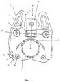
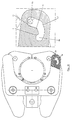
- the pressing tongs shown in Figure 1 which is a first embodiment of an inventive Device is symmetrical, so that only the components on the left side labeled were. It has two press legs 3, on which shown in the drawing below a pressing jaw pivot pin 3a is provided at the front ends. On every Swivel pin 3a is each a press jaw 1 pivotally mounted; the Press jaw 1 a recording 1a. A third press jaw is still used for pressing 2 needed, with the help of a base bracket 6 a fixed part of the pressing tongs forms.
- the press legs 3 also have attached approximately in their central region Press leg pin 3b, which at the same time the pivot axis for the press leg 3 establish.
- the side plate 5 On the press leg bolts 3b, the side plate 5 is shown, which to this Purpose the press leg bolt receptacles 5f.
- the side plate 5 is again over Brackets 7 attached to the press jaw 2.
- the inside of the press legs 3 have a Control set 4.
- This control link 4 is designed so that one spreading rollers Power transmission device (not shown) can run along it and the Spread position, i.e. the angular position of the press leg 3 with respect to the by Press leg pin 3b can change the press leg pivot axis.
- the press legs 3 and their control link 4 are designed so that spreading rollers, which in Arrow direction 8 are pushed towards the side plate when the control link runs along 4 initiate the pressing process, i.e. the press jaws 1 towards each other and in the direction of Guide press jaw 2.
- each of the press jaws 1 comprises, as can be seen in the closed state of FIG. 1, the one to be processed Body at about an angle of 120 °.
- the material has to be pressed Press sleeve no longer flow over long distances, as is the case with two-jaw pressing tongs the case is (180 °). The material flow during pressing is thus better distributed, structural weakening in the press sleeve can be reduced.
- the forces arising from such a pressing process To be received.
- the fixed part, that is, the basic bracket 6 must be at one Press process absorb forces that correspond to a load of about 3 to 4 t.
- the Press jaws take up loads that correspond to about 10 t, while the press leg bolts 3b can take loads that find their equivalent at 20 t.
- the individual components must therefore with regard to the material, processing and their Sizing should be designed accordingly.
- the forces depend on the size of the pliers and depending on the sleeve diameter to be pressed. The increase in noise has an effect but not so dramatically that with the same pliers not sleeve diameters of about 40 to 50 mm could be pressed.
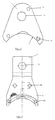
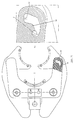
- FIG. 2 shows a view of a side plate 5 from the lower side in FIG. 1 this side plates 5 is arranged on each side of the pressing tongs.
- the side plate 5 has a fastening part with the receptacles 5f for the press leg pivot pin and the attachment 7 on the base bracket 6 and two guide extensions 5d, of which the one arranged on the right in FIG. 2 is discussed in more detail.
- the guide link 5a is provided as a recess. she has a kidney-shaped form with a completely rounded course.
- the guide link 5a has the two end positions 5b and 5c, between which there is a locking projection 5e.
- a spring receptacle 5g is attached around the receptacle 5f, which is shown on the right.
- a here to be introduced spring acts between the side plate 5 and the press leg 3, and in such a way that this press leg 3 is biased in the closing direction of the pliers.
- the enlarged detail X in FIG. 2 shows the guide link 5a and its functional Inner edges I, II and III and the locking projection 5e in more detail.
- the inner edges I, II and III together with the locking projection 5e each take on their own management function with the possible actuation of the pressing tongs. This management function will be explained later an opening process of the pressing tongs is shown in detail.
- the first inner edge section I lies in the area of the end position 5b in front of the locking projection 5e, the inner edge section II is behind it.
- the inner edge section III lies opposite the latching extension 5e.
- the backdrop guide described above now serves the movement of the press jaws 1 to control and so that this from a machining position to a released position can switch.
- FIG. 3 shows a pressing jaw 1 for the pressing tongs from FIG. 1 individually.
- she has a receptacle 1a for the press jaw pivot pin 3a, through which their Swivel axis is set.
- the contact surface of the press jaw 1 is identified by the reference symbol 1c.
- Via connections 1d, for example, inserts in the Attack area of the press jaw 1 are used.
- a guide pin 1b of the press jaw 1 is shown at the top right in FIG.
- This Guide bolt engages in the guide link when the pressing tongs are assembled 5a of the side plate 5.
- By the respective position of the engaging pin 1b in the Guide link 5a becomes the processing position or the released position of the press jaw 1 set.
- FIG 4 shows the fixed press jaw 2, which is integrally formed with the base bracket 6 is. About the brackets 2a, the fixed press jaw on the bracket 7 (see Figure 2) Side plate attached.
- a press insert (not shown) can also be attached to the fixed press jaw 2 via connections 2d. be attached.
- the base bracket 6 On the one-piece with the fixed press jaw 2 basic bracket 6 is a Receiving hole 6a provided.
- the base bracket 6 is fork-shaped; There are thus two of the plates shown in FIG. 4 with the reference number 6 in front of one another.
- a power transmission device is located in the receptacle 6a, for example with a retaining bolt attached to the pressing tongs with spreading rollers.
- Figure 5 shows a press leg 3 for the pressing tongs according to the invention in a single representation.
- the press leg 3 on the one hand has the control link 4 on the Spreading rollers run along a power transmission device and on the other hand on the right side a receptacle 3c for a press jaw pivot pin 3a. This can over the hole feedthrough, not designated, are attached.
- the receptacle 3d for a press leg pin 3b is shown in the center of the press leg 3.
- a spring receptacle 3e is shown, into which a torsion spring is used between the side plate 5 (see Figure 2) and the press leg 3 so acts that this is biased in the closed position of the pliers.
- FIG. 1 shows the pressing tongs in the closed state
- Figure 1 which shows the pressing tongs in the closed state
- Figure 1 is in left guide extension of the side plate 5 dashed the one provided on the underside Guide link 5a and the engaging pin 1b shown.
- the engaging pin 1b Located in the closed state the engaging pin 1b at the end position 5c of the guide link shown in FIG 5a.
- the press jaw 1 With the movement of the spreading rollers over the guide link 4 of the press legs 3 opposite to the direction of arrow 8 for releasing the crimping tool is with such Back-up guide the press jaw 1 is now relieved. This will solve the problem Press jaw 1 held by the press sleeve. By removing the compression sleeve, the Press jaw then in the open position.
- the press jaws 1 are first in their released position, i.e. with the Engagement bolt 1b near the end position 5b, brought to the press sleeve. Shortly before the actual pressing process is then controlled by the leg movement, by the Control link 5a, the press jaw 1 brought into its processing position by the Engagement bolt 1b is guided back to the point shown in Figure 1. Then the Start the pressing process.
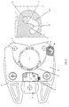
- Figures 6 to 9 each show a pair of pressing tongs on the left, the components of which are those in Figure 1 correspond, and which are therefore not described again individually.
- the pressing tongs shown in FIG. 6 have a component not yet discussed Bracket H, via which, for example, a fork-shaped positioning device the side plate 5 can be attached.
- a positioning device is used easier handling of the pressing tongs and, for example, engages in a prefabricated groove on a press sleeve in order to position the pliers appropriately during the pressing process guarantee.
- FIG. 6 shows the pressing tongs according to the first embodiment of the invention in one closed position, i.e. during the pressing process.
- the press jaws 1 and 2 are complete hit each other.
- the breakout Link guide 5a shown with the engaging engaging pin 1b; an enlargement this outbreak is shown to the right of the pliers.
- the engaging pin 1b is in the end position 5c, without one To stand side wall of the backdrop guide.
- the pressing force is in this position do not transfer to the engaging pin 1b via any inner edge.
- Figure 7 now shows the state of the pliers shortly after the pressing process, namely in the state where the process begins, in which the crimping pliers are not shown pressed sleeve is withdrawn.
- the engaging pin 1b overlaps the locking projection 5e further along the functional inner edge section I and comes in the open Finally position at the end position 5b.
- This position of the pressing tongs is shown in FIG. 8 shown.
- the press jaws 1 are pivoted completely into the open position, i.e. the pressing tongs is completely removed from the pressed sleeve.
- the inner edge section I is also in terms of its length, the angular position and the Curvature designed so that the movement can take place without inhibition.
- FIG. 9 now shows a further sequence of movements of the pliers, specifically for the case if this is done manually by compressing the left-hand ends of the press legs 3 is opened.
- the engagement pin 1b runs on the functional one Inner edge section III of the link guide 5a along which the locking projection 5e opposite.
- the engaging pin 1b is along the edge III passed from position 5c to position 5b without other edges of the guide link 5a to touch.
- the inner edge section III is also in terms of length, curvature and Angular position designed so that manual opening can be done without inhibition.
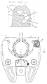
- Figures 10 to 12 show the opening process shown in Figures 6 to 8 during Pulling off the pliers from a pressed sleeve for a pressing tongs according to another Embodiment of the present invention.
- the pliers shown in Figures 10 to 13 is intended for pressing sleeves of larger diameters.
- FIG. 13 in turn shows the sequence of movements in the guide in manual Open this crimping tool.
- FIGS. 10 to 12 and in FIG. 13 does not differ fundamentally by those discussed above with reference to Figures 6 through 9.
- This second Embodiment is presented only to make it clear that the shape of the link guide 5a must be adapted to the size of the pressing tongs.
- the functional Inner edges I, II and III of the guide link 5a according to the second embodiment are in turn the length, the angular position and the curvature designed so that an uninhibited transfer of the engaging pin 1b between the two end positions 5b and 5c can take place.
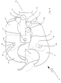
- pressing tongs is a first embodiment of a device according to the invention, hereinafter referred to as pressing tongs.
- the pressing tongs 10 have pressing jaws 12, on the one hand on their mutually facing sides in each case a pressing surface 14 and a control link 17, 17a are provided.
- the upper Press jaw 12 with the control link 17 is in a fully swiveled position, while the lower press jaw 12 with the control cam 17a in an open position is shown.
- Each press jaw 12 is pivotable about a pivot point or axis 16a, 16b on one or mounted on two holding plates 48.
- the holding plate or plates 48 are on the Retain drive member 34 via a construction for supporting the press jaws.
- the basic training of section 34 can with respect to the design of the transmission. of Motors, especially electric motors, and the like, as according to the generic Be a document that is expressly included in the disclosure content of the present registration documents is expressly included by reference, since there Features are listed that in combination with the teaching disclosed here invention quality can have.
- the power arm of a respective press jaw 12 is connected with various and merging control curves or scenes 17, 17a, 22 provided. If the Roll spreading rollers 18, 18a over these control cams, guide the press jaws 12 pivoted about the pivot points or axes 16a, 16b and operated by the retreat located spreading rollers 18, 18a, a pivoting movement, which then for pressing a press sleeve (not shown, or see Fig. 21 to 23) leads.
- Interlocking areas 33a, 33b can be provided at the ends of the force arms 32 be, which on the one hand are designed to open the push / pull rod which the spreading rollers 18, 18a are articulated to pass between the force arms, and on the other hand, they are designed so that they can interlock when open, to increase the opening angle between the two press jaws 12.
- the Surface 33a symmetrical to the axis of symmetry 9 of the pressing tongs 10 as a narrowed Rolling surface may be formed, while the rolling surface 33b essentially in two Rolling surfaces of equal size can be divided so that the rolling surface 33a between the Portions of the rolling surface 33b can be inserted.
- the appropriate training also describes and also insofar in the disclosure of the present application documents is explicitly included.
- pivot points or axes 16a, 16b on the holding plates 48 in Guide curves 44 are guided, namely between two extreme points, namely to one of the insertion or removal point 40 and the pressing position 42.
- the example is Pivot axis 16b shown in the removal or insertion position for the press jaw 12.
- the pivot axis 16a is shown in the pressing position 42.
- the guide curve 44 can also be provided in the press jaws while the Pivot axes 16a, 16b are firmly connected to the holding plates.
- the press jaws 12 can both manually and automatically by a corresponding Movement of the spreading rollers 18, 18a along the control curves 17, 17a in the two Extreme positions 40, 42 are transferred.
- the guide curve 44 can be equipped with a turning point be so that the press jaws 12 by overcoming the turning point by their respective pivot axes 16a, 16b to the axis or plane of symmetry 9 at least partially or be aligned approximately in parallel, then by continuing the Movement of the pivot axes 16a, 16b in the appropriately designed guide curves to carry out a pressing in which the material of the pressing sleeve during the pressing operation does not have to travel long distances, so that only slight deformations occur.
- the inner surfaces of the pressing surfaces 14 can be designed so that there are inserts for insert different diameters of different sleeve sizes into the press jaws leave, so that a set of press jaws with various inserts for some pipe diameter or sleeve diameter can be used. It is also possible on the press surfaces 14 slide or roller bearings to be provided, which then during the swiveling process compared to Make a swiveling movement at least on one side, so that a radialization of the forces applied by the pivoting process leads to the fact that also a small material flow from the rear, assigned to the control curves 17 Area of the pressing surfaces 14 to the front area occurs.
- Fig. 15 the basic configuration of the press jaws 12 of the embodiment is one Crimping pliers 50 are the same as those in FIG. 14.
- the active pressing position 52 is seated here at the upper end of the guide curve 56 and is opposite the removal or insertion position 54 angularly offset, so that in principle there is a guide curve 56, the compared to which is rotated by 180 degrees according to FIG. 14.
- the embodiment 10 according to FIG. 14 is in principle different stages of the possible movements.
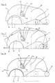
- FIG. 16 shows a pressing tongs with features according to the invention, for example according to FIG. 14, on Start of a pressing process, i.e. during the pre-pressing, when the pressing surface 14 this begins to encompass the sleeve 99 shown as a pitch circle.
- the spreading roller 18 is in the Term, pulled backward from the pivot point 16a via the facial expressions described to become.
- the pivot point 16a is firmly occupied in the active position 42 here.
- FIG. 17 shows the beginning of full pressing and FIG. 18 shows the end of pressing, when the compression sleeve has assumed its final shape and the one to be carried out Connection is established.
- the guide link or the guide links 44, 56 also are provided at least one cam section, which acts on the force transmission device on this the processing elements, preferably press jaws 12, in one Processing position transferred.
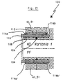
- 21 to 23 are preferred embodiments of a line connection or a line connection 100, 200, 300 with a preferred compression sleeve 112, 212, 312 reproduced.
- the essence of the press sleeve 112, 212, 312 shown is at least one projection 114a, 214a, 314a which is circumferential in some areas and which at least at one end of the cylindrical sleeve 112 is provided.
- the compression sleeve 112, 212 is at each end a corresponding cantilever is provided, the end of the inward on the Cylinder axis is too formed or bent.
- a press jaw 12 acts on the press sleeve 112, 212 or 312, the at least a projection 114a, 214a, 314a is bent inward on a line 210 and is into this pushed in, so that the positive and non-positive intervention of the former Cantilever 114a ', 214a' an additional holding force on the line end 110, 210, 310 is exercised.
- An additional seal 106, 206, 306 also carries in connection with a trough-shaped Surface structure 108, 208, 308 on a support sleeve 104, 204, 304 to a dense Connection of the line to the connection shown 100, 200, 300 at.
- the end of the pipeline 110, 210, 310 to be connected can be spaced apart from the Connection 102, 202 are arranged or directly abut the stop 302 or but via a separating sleeve 320, preferably made of non-conductive material, such as plastic, adjoin.
- Figs. 21-23 are of various embodiments preferred sleeves in an uncompressed state, the lower sections show 21, 22, the sleeves, after pressing over the pressing inserts 41, 51 took place.
- Line 110, 210 or sleeve 212, 112 is left a distance for visual inspection the proper seat of the sleeve or the line end opposite the stop 102, 202 and thus can be checked with respect to the support sleeve 104, 204.
- FIG. 23 In the lower section of FIG. 23 is one with the characteristics according to FIGS. 21, 22 equipped press sleeve 312, as shown in connection with the ring member 320 for the Storage and transport fixed to a support sleeve or to the stop 302 can be.
- the radially inner end of the ring part 320 places the compression sleeve 312 on the Support sleeve 304 firmly, with a recess 311 on the stop 302 with the hook-like trained cantilever 314a can come into a clamping engagement.
Landscapes
- Engineering & Computer Science (AREA)
- Mechanical Engineering (AREA)
- Hand Tools For Fitting Together And Separating, Or Other Hand Tools (AREA)
- Press Drives And Press Lines (AREA)
Applications Claiming Priority (4)
| Application Number | Priority Date | Filing Date | Title |
|---|---|---|---|
| DE19722418 | 1997-05-28 | ||
| DE19722418 | 1997-05-28 | ||
| DE19813778A DE19813778A1 (de) | 1997-05-28 | 1998-03-27 | Bearbeitungsvorrichtung, insbesondere Preßzange |
| DE19813778 | 1998-03-27 |
Publications (2)
| Publication Number | Publication Date |
|---|---|
| EP0882531A2 true EP0882531A2 (fr) | 1998-12-09 |
| EP0882531A3 EP0882531A3 (fr) | 2002-10-16 |
Family
ID=26036946
Family Applications (1)
| Application Number | Title | Priority Date | Filing Date |
|---|---|---|---|
| EP98109749A Withdrawn EP0882531A3 (fr) | 1997-05-28 | 1998-05-28 | Dispositif d'usinage, en particulier pince à sertir |
Country Status (1)
| Country | Link |
|---|---|
| EP (1) | EP0882531A3 (fr) |
Cited By (3)
| Publication number | Priority date | Publication date | Assignee | Title |
|---|---|---|---|---|
| EP2072188A1 (fr) * | 2007-12-17 | 2009-06-24 | VIEGA GmbH & Co. KG. | Outil de presse doté d'un mécanisme de tension bistable |
| DE102008036209A1 (de) * | 2008-08-02 | 2010-04-08 | Uponor Ab | Schneidwerkzeug für ein Kunststoff aufweisendes Rohr, insbesondere Kunststoffrohr oder Kunststoff/Metall- Verbundrohr |
| CN112060001A (zh) * | 2020-09-28 | 2020-12-11 | 烟台艾迪精密机械股份有限公司 | 一种救援用剪切破拆扩张钳及控制系统 |
Family Cites Families (4)
| Publication number | Priority date | Publication date | Assignee | Title |
|---|---|---|---|---|
| DE9007414U1 (de) * | 1990-04-12 | 1991-07-18 | Dischler, Helmut, Dipl.-Ing., 4040 Neuss | Preßwerkzeug |
| DE4206439A1 (de) * | 1992-02-29 | 1993-09-02 | Tectonic Gmbh | Presswerkzeug zum aufpressen eines zylindrischen pressteils oder eines einen zylindrischen abschnitt aufweisenden pressteils auf ein rundprofil, insbesondere eine rohrleitung |
| DE4300934A1 (de) * | 1993-01-15 | 1994-08-18 | Hewing Gmbh | Preßwerkzeug zum Aufpressen eines zylindrischen Preßteils oder eines einen zylindrischen Preßabschnitt aufweisenden Preßteils auf ein Rundprofil |
| DE4321235C2 (de) * | 1993-06-25 | 1996-05-30 | Kirchner Fraenk Rohr | Preßzange |
-
1998
- 1998-05-28 EP EP98109749A patent/EP0882531A3/fr not_active Withdrawn
Cited By (5)
| Publication number | Priority date | Publication date | Assignee | Title |
|---|---|---|---|---|
| EP2072188A1 (fr) * | 2007-12-17 | 2009-06-24 | VIEGA GmbH & Co. KG. | Outil de presse doté d'un mécanisme de tension bistable |
| DE102008036209A1 (de) * | 2008-08-02 | 2010-04-08 | Uponor Ab | Schneidwerkzeug für ein Kunststoff aufweisendes Rohr, insbesondere Kunststoffrohr oder Kunststoff/Metall- Verbundrohr |
| DE102008036209B4 (de) * | 2008-08-02 | 2010-12-02 | Uponor Innovation Ab | Schneidwerkzeug für ein Kunststoff aufweisendes Rohr, insbesondere Kunststoffrohr oder Kunststoff/Metall-Verbundrohr |
| CN112060001A (zh) * | 2020-09-28 | 2020-12-11 | 烟台艾迪精密机械股份有限公司 | 一种救援用剪切破拆扩张钳及控制系统 |
| CN112060001B (zh) * | 2020-09-28 | 2023-11-28 | 烟台艾迪精密机械股份有限公司 | 一种救援用剪切破拆扩张钳及控制系统 |
Also Published As
| Publication number | Publication date |
|---|---|
| EP0882531A3 (fr) | 2002-10-16 |
Similar Documents
| Publication | Publication Date | Title |
|---|---|---|
| EP0451806B1 (fr) | Outil de pressage | |
| DE3423283C2 (fr) | ||
| DE102009032113B4 (de) | Presswerkzeug sowie Verfahren zum Verpressen von insbesondere rohrförmigen Werkstücken | |
| EP0531897B1 (fr) | Outil de pressage pour sertir un objet pressé cylindrique, ou un objet ayant une section cylindrique sur un profilé cylindrique, notamment une conduite | |
| DE10132413C2 (de) | Verfahren und Zange zum Schneiden amorpher Lichtwellenleiterkabel | |
| DE3890753C2 (de) | Apparat zum Drehen eines rohrförmigen Bohrungselements um seine Längsachse | |
| EP2744626B1 (fr) | Dispositif de compression | |
| DE202015107029U1 (de) | Spannmittel für eine Rohrausklinkmaschine | |
| DE3142279A1 (de) | "haltezange mit aufblasbarem greifbelag" | |
| EP2428452B1 (fr) | Procédé et dispositif de banderolage pour l'installation de bandes de cerclage autour de pièces d'emballage | |
| EP2522464B1 (fr) | Mordache et procédé de fabrication d'un emmanchement par pressage | |
| EP3209440A1 (fr) | Outil de pressage | |
| DE10106363C1 (de) | Pressenkopf für das Verbinden von Rohrleitungen | |
| DE4446503C1 (de) | Handwerkzeug mit zwei gegeneinander beweglichen Halterungen für die Aufnahme von Werkstücken und/oder Werkzeugen | |
| DE3538919C2 (fr) | ||
| DE102014115358A1 (de) | Presswerkzeug | |
| DE19813778A1 (de) | Bearbeitungsvorrichtung, insbesondere Preßzange | |
| EP4129575B1 (fr) | Dispositif de montage d'anneau, ainsi que procédé de réglage d'un dispositif de montage d'anneau | |
| DE3835173C2 (fr) | ||
| DE4321235C2 (de) | Preßzange | |
| DE102015122651B4 (de) | Spannmittel für eine Rohrausklinkmaschine und Verfahren dazu | |
| DE10217266B4 (de) | Preßzange zum Verpressen von Hohlkörpern | |
| DE10243707C5 (de) | Handzange zum Verpressen von Rohrverbindungen | |
| DE9217886U1 (de) | Preßgerät zum Aufpressen von Hülsen, Kabelschuhpressen o.dgl. | |
| DE19539580B4 (de) | Presszange zum Verpressen von Kontaktelementen |
Legal Events
| Date | Code | Title | Description |
|---|---|---|---|
| PUAI | Public reference made under article 153(3) epc to a published international application that has entered the european phase |
Free format text: ORIGINAL CODE: 0009012 |
|
| AK | Designated contracting states |
Kind code of ref document: A2 Designated state(s): AT BE CH CY DE DK ES FI FR GB GR IE IT LI LU MC NL PT SE |
|
| AX | Request for extension of the european patent |
Free format text: AL;LT;LV;MK;RO;SI |
|
| PUAL | Search report despatched |
Free format text: ORIGINAL CODE: 0009013 |
|
| AK | Designated contracting states |
Kind code of ref document: A3 Designated state(s): AT BE CH CY DE DK ES FI FR GB GR IE IT LI LU MC NL PT SE |
|
| AX | Request for extension of the european patent |
Free format text: AL;LT;LV;MK;RO;SI |
|
| RIC1 | Information provided on ipc code assigned before grant |
Free format text: 7B 21D 39/04 A, 7B 25B 27/14 B, 7B 25B 27/10 B |
|
| AKX | Designation fees paid | ||
| REG | Reference to a national code |
Ref country code: DE Ref legal event code: 8566 |
|
| STAA | Information on the status of an ep patent application or granted ep patent |
Free format text: STATUS: THE APPLICATION IS DEEMED TO BE WITHDRAWN |
|
| 18D | Application deemed to be withdrawn |
Effective date: 20030417 |