EP0882567A2 - Querschweisseinrichtung und Verfahren zum Einstellen und Bewegen der Schweissstempel in einer Querschweisseinrichtung - Google Patents
Querschweisseinrichtung und Verfahren zum Einstellen und Bewegen der Schweissstempel in einer Querschweisseinrichtung Download PDFInfo
- Publication number
- EP0882567A2 EP0882567A2 EP98102988A EP98102988A EP0882567A2 EP 0882567 A2 EP0882567 A2 EP 0882567A2 EP 98102988 A EP98102988 A EP 98102988A EP 98102988 A EP98102988 A EP 98102988A EP 0882567 A2 EP0882567 A2 EP 0882567A2
- Authority
- EP
- European Patent Office
- Prior art keywords
- welding
- stamp
- drive belt
- stamps
- film web
- Prior art date
- Legal status (The legal status is an assumption and is not a legal conclusion. Google has not performed a legal analysis and makes no representation as to the accuracy of the status listed.)
- Withdrawn
Links
Images


Classifications
-
- B—PERFORMING OPERATIONS; TRANSPORTING
- B65—CONVEYING; PACKING; STORING; HANDLING THIN OR FILAMENTARY MATERIAL
- B65B—MACHINES, APPARATUS OR DEVICES FOR, OR METHODS OF, PACKAGING ARTICLES OR MATERIALS; UNPACKING
- B65B51/00—Devices for, or methods of, sealing or securing package folds or closures; Devices for gathering or twisting wrappers, or necks of bags
- B65B51/10—Applying or generating heat or pressure or combinations thereof
- B65B51/26—Devices specially adapted for producing transverse or longitudinal seams in webs or tubes
- B65B51/30—Devices, e.g. jaws, for applying pressure and heat, e.g. for subdividing filled tubes
-
- B—PERFORMING OPERATIONS; TRANSPORTING
- B29—WORKING OF PLASTICS; WORKING OF SUBSTANCES IN A PLASTIC STATE IN GENERAL
- B29C—SHAPING OR JOINING OF PLASTICS; SHAPING OF MATERIAL IN A PLASTIC STATE, NOT OTHERWISE PROVIDED FOR; AFTER-TREATMENT OF THE SHAPED PRODUCTS, e.g. REPAIRING
- B29C65/00—Joining or sealing of preformed parts, e.g. welding of plastics materials; Apparatus therefor
- B29C65/02—Joining or sealing of preformed parts, e.g. welding of plastics materials; Apparatus therefor by heating, with or without pressure
- B29C65/18—Joining or sealing of preformed parts, e.g. welding of plastics materials; Apparatus therefor by heating, with or without pressure using heated tools
-
- B—PERFORMING OPERATIONS; TRANSPORTING
- B29—WORKING OF PLASTICS; WORKING OF SUBSTANCES IN A PLASTIC STATE IN GENERAL
- B29C—SHAPING OR JOINING OF PLASTICS; SHAPING OF MATERIAL IN A PLASTIC STATE, NOT OTHERWISE PROVIDED FOR; AFTER-TREATMENT OF THE SHAPED PRODUCTS, e.g. REPAIRING
- B29C66/00—General aspects of processes or apparatus for joining preformed parts
- B29C66/40—General aspects of joining substantially flat articles, e.g. plates, sheets or web-like materials; Making flat seams in tubular or hollow articles; Joining single elements to substantially flat surfaces
- B29C66/41—Joining substantially flat articles ; Making flat seams in tubular or hollow articles
- B29C66/43—Joining a relatively small portion of the surface of said articles
- B29C66/431—Joining the articles to themselves
-
- B—PERFORMING OPERATIONS; TRANSPORTING
- B29—WORKING OF PLASTICS; WORKING OF SUBSTANCES IN A PLASTIC STATE IN GENERAL
- B29C—SHAPING OR JOINING OF PLASTICS; SHAPING OF MATERIAL IN A PLASTIC STATE, NOT OTHERWISE PROVIDED FOR; AFTER-TREATMENT OF THE SHAPED PRODUCTS, e.g. REPAIRING
- B29C66/00—General aspects of processes or apparatus for joining preformed parts
- B29C66/80—General aspects of machine operations or constructions and parts thereof
- B29C66/81—General aspects of the pressing elements, i.e. the elements applying pressure on the parts to be joined in the area to be joined, e.g. the welding jaws or clamps
- B29C66/816—General aspects of the pressing elements, i.e. the elements applying pressure on the parts to be joined in the area to be joined, e.g. the welding jaws or clamps characterised by the mounting of the pressing elements, e.g. of the welding jaws or clamps
- B29C66/8167—Quick change joining tools or surfaces
-
- B—PERFORMING OPERATIONS; TRANSPORTING
- B29—WORKING OF PLASTICS; WORKING OF SUBSTANCES IN A PLASTIC STATE IN GENERAL
- B29C—SHAPING OR JOINING OF PLASTICS; SHAPING OF MATERIAL IN A PLASTIC STATE, NOT OTHERWISE PROVIDED FOR; AFTER-TREATMENT OF THE SHAPED PRODUCTS, e.g. REPAIRING
- B29C66/00—General aspects of processes or apparatus for joining preformed parts
- B29C66/80—General aspects of machine operations or constructions and parts thereof
- B29C66/83—General aspects of machine operations or constructions and parts thereof characterised by the movement of the joining or pressing tools
- B29C66/834—General aspects of machine operations or constructions and parts thereof characterised by the movement of the joining or pressing tools moving with the parts to be joined
- B29C66/8351—Jaws mounted on rollers, cylinders, drums, bands, belts or chains; Flying jaws
- B29C66/83541—Jaws mounted on rollers, cylinders, drums, bands, belts or chains; Flying jaws flying jaws, e.g. jaws mounted on crank mechanisms or following a hand over hand movement
- B29C66/83543—Jaws mounted on rollers, cylinders, drums, bands, belts or chains; Flying jaws flying jaws, e.g. jaws mounted on crank mechanisms or following a hand over hand movement cooperating flying jaws
-
- B—PERFORMING OPERATIONS; TRANSPORTING
- B29—WORKING OF PLASTICS; WORKING OF SUBSTANCES IN A PLASTIC STATE IN GENERAL
- B29C—SHAPING OR JOINING OF PLASTICS; SHAPING OF MATERIAL IN A PLASTIC STATE, NOT OTHERWISE PROVIDED FOR; AFTER-TREATMENT OF THE SHAPED PRODUCTS, e.g. REPAIRING
- B29C66/00—General aspects of processes or apparatus for joining preformed parts
- B29C66/80—General aspects of machine operations or constructions and parts thereof
- B29C66/84—Specific machine types or machines suitable for specific applications
- B29C66/841—Machines or tools adaptable for making articles of different dimensions or shapes or for making joints of different dimensions
- B29C66/8412—Machines or tools adaptable for making articles of different dimensions or shapes or for making joints of different dimensions of different length, width or height
-
- B—PERFORMING OPERATIONS; TRANSPORTING
- B29—WORKING OF PLASTICS; WORKING OF SUBSTANCES IN A PLASTIC STATE IN GENERAL
- B29C—SHAPING OR JOINING OF PLASTICS; SHAPING OF MATERIAL IN A PLASTIC STATE, NOT OTHERWISE PROVIDED FOR; AFTER-TREATMENT OF THE SHAPED PRODUCTS, e.g. REPAIRING
- B29C66/00—General aspects of processes or apparatus for joining preformed parts
- B29C66/80—General aspects of machine operations or constructions and parts thereof
- B29C66/84—Specific machine types or machines suitable for specific applications
- B29C66/849—Packaging machines
-
- B—PERFORMING OPERATIONS; TRANSPORTING
- B29—WORKING OF PLASTICS; WORKING OF SUBSTANCES IN A PLASTIC STATE IN GENERAL
- B29C—SHAPING OR JOINING OF PLASTICS; SHAPING OF MATERIAL IN A PLASTIC STATE, NOT OTHERWISE PROVIDED FOR; AFTER-TREATMENT OF THE SHAPED PRODUCTS, e.g. REPAIRING
- B29C66/00—General aspects of processes or apparatus for joining preformed parts
- B29C66/01—General aspects dealing with the joint area or with the area to be joined
- B29C66/05—Particular design of joint configurations
- B29C66/10—Particular design of joint configurations particular design of the joint cross-sections
- B29C66/11—Joint cross-sections comprising a single joint-segment, i.e. one of the parts to be joined comprising a single joint-segment in the joint cross-section
- B29C66/112—Single lapped joints
- B29C66/1122—Single lap to lap joints, i.e. overlap joints
Definitions
- the present invention relates to a cross welding device for endless Packaging machines using film webs with a first and a second welding stamp having a welding unit, the Cross welding takes place in continuous operation and the welding stamp both by means of a first motor perpendicular to the direction of movement of the Foil web as well as by means of another motor independently of it parallel to Direction of movement of the film web are movable.
- the invention relates also a method for setting and moving welding stamps in such a welding device.
- Packaging machines use one Half-tube folded film webs and are therefore also called Tubular bag machines called.
- the continuously working Packaging machines transport the film continuously without Standstill and the sealing of the film wrapping the packaged goods happens with moving film and moving packaged goods.
- the film is cut to length
- the length of the packaged goods corresponds to this type of Packaging machines by means of a moving along a short distance Cross welding device, which after welding back back into your Starting position moves.
- DE 44 25 207 A1 discloses the movement of the Cross sealing device parallel to the film web by means of a drive device and the movement of the welding stamp perpendicular to the film surface by means of another engine independently.
- the distance between the welding stamps must be readjusted take place so that the tubular films, especially in the case of large packaged goods, in the middle the height of the packaged goods is welded.
- These settings are common performed manually with handwheels or the like.
- the present invention is therefore based on the object of one possibility the automatic adjustment of the distance between the welding stamps to propose, by means of the already existing drive devices for the Cross welding device is accomplished.
- This task is performed by a cross welding device with the features of Main claim solved. Further advantageous configurations are the See subclaims. The task is also through a process solved with the features of the method claim. More beneficial Refinements of the method are related to this See subclaims.
- the welding unit is parallel to one another Foil web movable carriage arranged and has two on both sides of the Welding stamp holder arranged on the film web.
- the Welding stamp holders are each drive belts via deflection rollers arranged to carry the welding stamp and to carry out the Cross welding the welding stamps arranged transversely to the film web Move perpendicular to the surface of the film web.
- a sweat stamp, preferably that facing the carriage is one in each case Clamping device in the form of a three-roller guide on the respective drive belt held, which has three rollers arranged essentially in a line, the drive belt wrapping around the middle roller.
- the two outer ones Rollers are freely rotatable, while the middle roller has clutch discs are separable from each other against a spring force, rotatably with the Welding stamp is connected.
- the welding stamps are so they are on each other can be moved on the opposite strands of the drive belt attached.
- the three-roller guide in the embodiment described above ensures that the lower welding stamp as well as the upper one Welding stamp is firmly attached to the drive belt and its movement participates, but can also be detached from the drive belt.
- the middle roller has clutch disks
- this can be a pen or separately driven pneumatic cylinder or other the Devices familiar to those skilled in the art can be detached from the welding stamp.
- the middle roller is freely rotatable, so that the drive belt over the three rollers can be performed without the welding stamp moving.
- the distance between that can continue at the Drive belt fixed (upper) and the loosened (lower) welding stamp be changed according to the height of the packaged goods.
- This change can consequently done by the same drive that also the welding stamp moving towards each other, especially when using intelligent Servomotors that are equipped with a corresponding computer unit, can be carried out automatically and precisely.
- the middle roller is mounted on a hollow axle, into which a push-out pin can be inserted at one end. That push pin can either be directly connected to the welding stamp holder or removed be arranged at a fixed position.
- a push-out pin can either be directly connected to the welding stamp holder or removed be arranged at a fixed position.
- Extraction pins are firmly attached to a support frame and the slide is for Separate the middle rolls from the welding stamp to them Removable push pins.
- the attachment of the middle roller is the roller on its side facing away from one end of the hollow axis with a Coupling disc provided, which in a second clutch disc, which on a non-rotatable holding disc that can be moved axially on the spot against a spring force is appropriate.
- the clutch discs must be as fine as possible can be engaged to each other to form the range of To keep the adjustment options of the welding stamp as large as possible. At the A friction clutch would be the cheapest if it had sufficient holding force guaranteed.
- the clutch discs are fine-locking Switch clutch designed, for example as a claw clutch, or they are with a so-called Hirth serration.
- the embodiment is used for power transmission between the torque shaft and the welding unit on the carriage at least one the torque of the Shaft-receiving (main) drive pulley and in the area of the Welding stamp carrier for carrying out the movement of the welding stamp each uses a welding stamp drive pulley that has at least a (main) drive belt are connected to each other.
- the welding stamp is, as already mentioned above in connection with the Cross-welding device partially explained, for adjusting the distance of the Welding stamps to each other a welding stamp automatically from the Drive belt loosened, connect the relative position between the welding stamp and the drive belt according to the desired distance between the fixed welding stamp and the loosened welding stamp changed and then the loosened welding stamp automatically on the drive belt fixed.
- the invention thus provides a possibility that can only be achieved through use of the two drive motors required anyway as intelligent servomotors also the automatic adjustment of the welding stamp when changing the Packaged goods guaranteed.
- This enables the cross welding device to open quickly changing dimensions can be set.
- the Cross welding device a high due to as few moving masses Clock speed.
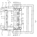
- FIG. 1 shows the cross welding device 1 with a support frame 2 on which the Welding unit 3 parallel to the film transport direction into the drawing plane is movable by means of a carriage 9.
- the welding unit 3 has the on both sides Foil sheet 4, 5 running perpendicular to the plane of the drawing on, each one guided over upper rollers 6 and lower rollers 7 Have drive belt 8.
- the drive belt 8 in both Welding stamp holder 4 is by means of a (main) drive belt 13, which Guide rollers 42 via a drive pulley 12, which is also on the carriage 9 is arranged, driven.
- the drive of the drive disk 12 takes place in this Embodiment, as below in connection with Figure 6 in more detail explained, via a torque shaft 37, which directly or, as shown, means a further drive belt 11 arranged on the torque shaft Pulley 41 driven by a motor 10 attached to the support frame 2 becomes.
- the upper welding stamp 14 is ( Figure 1) on both drive belts 8 on the left Trum 15 attached.
- the lower welding stamp 16 is over a three-roller guide 17, consisting of an upper and a lower loose roller 18, 19 and one middle, with the lower welding stamp 16 rotatably connected releasable role 20 attached to the right run 21 of the drive belt 8. If the Drive belt 8 is set in motion, the lower and move upper welding stamp 16, or 14 towards or away from each other.
- the distance between the welding punches 14, 16 corresponds to the height of the packaged goods can be varied, as mentioned, the lower welding punch 16 from that Drive belt 8 releasable, so that the motor 10, which is considered intelligent Servo drive is configured, the upper welding stamp 14 when stationary lower welding stamp 16 can be moved to the new distance adjust. This is explained in more detail below in connection with FIGS. 2 to 4 explained.
- FIG. 2 shows the lower welding stamp 16 in an enlarged representation with the three-roller guide 17 with the upper and lower a smaller one Diameter loose rollers 18 and 19 and the middle, normally non-rotatably connected but detachable, having a larger diameter than a toothed belt pulley trained role 20.
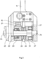
- Figure 3 shows the longitudinal section through the three-roller guide 17 in the area of middle roller designed as a toothed belt pulley 20.
- the middle one Toothed belt pulley 20 is mounted on the shaft 23 by means of ball bearings 22 at their ends 24 and 25 firmly connected to the lower welding punch 16 is.
- the axis 23 points in a common way corresponding longitudinal grooves or Springs to ensure torsional strength.
- the holding disc 31 is about Coil springs 27, which are supported on the lower welding punch 16, pressed against a further clutch disc 28, which with the middle Toothed pulley 20 is connected.
- the two clutch disks face toothing as fine as possible, for example from 5 ° to 7 °, in order to to be able to engage variably.
- the axis 23 is up to about the middle of the Holding disc 31 formed as a hollow axis and has an open end 24.
- In 3 is also the right strand 21 of the drive belt 8, which as Toothed belt is formed and the circumference of the central toothed belt pulley 20th encompasses, and the left strand 15 can be seen.
- Figure 5 shows the support frame 2 on which the carriage 9 together with the Welding unit 3 can move along the film transport direction.
- the drive for the movement parallel to the film web takes place in a known manner of a further motor 32, which is also designed as an intelligent servo drive is, and the drive belt 33 and 34, the latter with the carriage 9th is connected and is guided over the rollers 35 and 36.
- the figure shows the Extraction pin 29, which is firmly connected to the support frame 2. To adjust the welding stamp holder turns the carriage into a so-called ejection position driven in which the push pin 29 in the manner described above and Way into the shaft 23 and the lower welding stamp 16 of the Drive belt 8 releases.
- FIG. 6 which shows a plan view of the cross welding device 1, the two push pins 29 for the two three-roller guides 17 on the two Drive belt 8 of the welding stamp holders 4, 5 can be seen.
- the Power transmission from the engine 10 takes place via the drive belt 11 and Drive pulley 41 to a torque shaft 37.
- the carriage 9 moves along the rails 38 and the torque shaft 37.
- the torque shaft 37 is rotatable in the axial direction via the ball bearings 39 on the support frame 2 stored and is rotated via the drive pulley 41.
- the Torque shaft has grooves or springs running in the axial direction, the drive pulley 12 moved with the carriage, via which the Drive belt 13 ( Figure 1) runs, drives.
Landscapes
- Engineering & Computer Science (AREA)
- Mechanical Engineering (AREA)
- Containers And Plastic Fillers For Packaging (AREA)
- Auxiliary Devices For And Details Of Packaging Control (AREA)
- Lining Or Joining Of Plastics Or The Like (AREA)
Abstract
Description
- Figur 1
- eine Stirnansicht der Querschweißeinrichtung, wobei aus Vereinfachungsgründen nicht die Erfindung betreffende Abdeckungen oder Halterungen weggelassen sind,
- Figur 2
- eine vergrößerte schematische Darstellung des unteren Schweißstempels mit der Fixierung an den Antriebsriemen;
- Figur 3
- einen Längsschnitt durch die mittlere Rolle der Dreirollenführung;
- Figur 4
- die Seitenansicht der Dreirollenführung im Schnitt;
- Figur 5
- die Seitenansicht der Querschweißeinrichtung und
- Figur 6
- die Draufsicht auf die Querschweißeinrichtung.
Claims (12)
- Querschweißeinrichtung für endlose Folienbahnen verwendende Verpackungsmaschinen mit einer einen ersten und einen zweiten Schweißstempel aufweisenden Schweißeinheit, wobei die Querverschweißung im kontinuierlichen Betrieb erfolgt und die Schweißstempel sowohl mittels eines ersten Motors senkrecht zur Bewegungsrichtung der Folienbahn als auch mittels eines weiteren Motors unabhängig davon parallel zur Bewegungsrichtung der Folienbahn bewegbar sind, dadurch gekennzeichnet, daß die Schweißeinheit (3) auf einem parallel zur Folienbahn bewegbaren Schlitten (9) angeordnet ist und zwei beidseitig der Folienbahn angeordnete Schweißstempelhalter (4, 5) aufweist, in denen jeweils über Umlenkrollen (6, 7), Antriebsriemen (8) angeordnet sind, die die Schweißstempel (14, 16) tragen und zur Durchführung der Querverschweißung die quer zur Folienbahn angeordneten Schweißstempel (14, 16) senkrecht zur Oberfläche der Folienbahn bewegen, und ein Schweißstempel (16), vorzugsweise der dem Schlitten (9) zugewandte, über jeweils eine Dreirollenführung (17) am jeweiligen Antriebsriemen (8) gehalten ist, die drei im wesentlichen auf einer Linie angeordnete Rollen (18, 19, 20) aufweist, wobei der Antriebsriemen (8) die mittlere Rolle (20) umschlingt und die beiden äußeren Rollen (18, 19) frei drehbar sind, während die mittlere Rolle (20) über Kupplungsscheiben (26, 28), die gegen eine Federkraft voneinander trennbar sind, drehfest mit dem Schweißstempel (16) verbunden ist.
- Querschweißeinrichtung nach Anspruch 1, dadurch gekennzeichnet, daß die mittlere Rolle (20) der Dreirollenführung (17) auf einer wenigstens teilweise hohlen Achse (23) gelagert ist, in die an ihrem einen Ende (24) ein Ausdrückstift (29) einführbar ist.
- Querschweißeinrichtung nach Anspruch 2, dadurch gekennzeichnet, daß die mittlere Rolle (20) auf ihrer dem offenen Ende (24) der Hohlachse (23) abgewandten Seite eine Kupplungsscheibe (28) aufweist, die an einer zweiten Kupplungsscheibe (26), die an einer drehfesten, gegen eine Federkraft axial auf der Welle (23) bewegbaren Haltescheibe (31) angebracht ist, haftet.
- Querschweißeinrichtung nach Anspruch 3, dadurch gekennzeichnet, daß die Kupplungsscheiben (26, 28) als feinrastige Schaltkupplungen ausgebildet sind.
- Querschweißeinrichtung nach einem der Ansprüche 2 bis 4, dadurch gekennzeichnet, daß die Ausdrückstifte (29) fest an einem Tragrahmen (2) befestigt sind und der Schlitten (9) zum Trennen der mittleren Rollen (20) von dem Schweißstempel (16) bis zu den Ausdrückstiften (29) verfahrbar ist.
- Querschweißeinrichtung nach einem der vorangegangenen Ansprüche, dadurch gekennzeichnet, daß an einem Tragrahmen (2), gegenüber dem der Schlitten (9) parallel zur Folienbahn verfahrbar ist, eine in Folienlängsrichtung sich erstreckende und an dem Tragrahmen (2) axial drehbar gelagerte Drehmomentwelle (37) angeordnet ist, die über einen Servoantrieb (10) antreibbar ist und entlang der der Schlitten (9) bewegbar ist, und daß die Drehbewegung der Drehmomentwelle (37) mittels Kraftübertragungseinrichtungen auf die Antriebsriemen (8) der Schweißeinheit (3) übertragen wird.
- Querschweißeinrichtung nach Anspruch 6, dadurch gekennzeichnet, daß zur Kraftübertragung zwischen der Drehmomentwelle (37) und der Schweißeinheit (3) auf dem Schlitten (9) mindestens eine das Drehmoment der Drehmomentwelle (37) aufnehmende Antriebsscheibe (12) und im Bereich der Schweißstempelhalter (4) zur Durchführung der Bewegung der Schweißstempel (14, 16) jeweils eine Schweißstempel-Antriebsscheibe (7) angeordnet sind, die über mindestens einen Antriebsriemen (13) miteinander verbunden sind.
- Verfahren zum Einstellen und Bewegen von Schweißstempeln in einer Querschweißeinrichtung für endlose Folienbahnen verwendende Verpackungsmaschinen mit einer einen ersten und einen zweiten Schweißstempel aufweisenden Schweißeinheit, wobei die Querverschweißung im kontinuierlichen Betrieb erfolgt und die Schweißstempel sowohl mittels eines ersten Motors senkrecht zur Bewegungsrichtung der Folienbahn als auch mittels eines weiteren Motors unabhängig davon parallel zur Bewegungsrichtung der Folienbahn bewegt werden, dadurch gekennzeichnet, daß die Schweißstempel (14, 16) senkrecht zur Oberfläche der Folienbahn zur Durchführung des Schweißvorgangs mittels an beiden Enden der Schweißstempel angeordneter Antriebsriemen (8), an denen die Schweißstempel befestigt sind, bewegt werden und zur Verstellung des Abstandes der Schweißstempel zueinander ein Schweißstempel (16) automatisch von dem Antriebsriemen (8) gelöst, anschließend die relative Lage zwischen Schweißstempel und dem Antriebsriemen entsprechend dem gewünschten Abstand zwischen dem festen Schweißstempel und dem gelösten Schweißstempel verändert und darauffolgend der gelöste Schweißstempel automatisch an dem Antriebsriemen wieder fixiert wird.
- Verfahren nach Anspruch 8, dadurch gekennzeichnet, daß der gelöste Schweißstempel (16) in seiner Position gehalten und der Antriebsriemen (8) mit dem festen Schweißstempel (14) bis zu dem gewünschten Abstand verfahren wird.
- Verfahren nach Anspruch 8 oder 9, dadurch gekennzeichnet, daß der zu lösende Schweißstempel über eine Dreirollenführung (17) mit drei im wesentlichen auf einer Linie angeordneten Rollen (18, 19, 20) am Antriebsriemen (8) gehalten wird, indem der Antriebsriemen über die beiden äußeren beweglichen Rollen laufend schlangenlinienförmig um die mittlere fest mit dem Schweißstempel verbundene Rolle geführt wird, und zum Lösen des Schweißstempels von dem Antriebsriemen jeweils die Verbindung der mittleren Rolle von dem Schweißstempel gelöst wird.
- Verfahren nach einem der Ansprüche 8 bis 10, dadurch gekennzeichnet, daß zum Lösen des Schweißstempels (16) die Schweißeinheit (3) in eine Ausklinkposition verfahren wird.
- Verfahren nach Anspruch 11, dadurch gekennzeichnet, daß mit Erreichen der Ausklinkposition der Schweißstempel (16) von dem Antriebsriemen (8) gelöst und in seiner augenblicklichen Position gehalten und beim Wegfahren wieder an dem Antriebsriemen fixiert wird.
Applications Claiming Priority (2)
| Application Number | Priority Date | Filing Date | Title |
|---|---|---|---|
| DE19721594 | 1997-05-23 | ||
| DE19721594A DE19721594C1 (de) | 1997-05-23 | 1997-05-23 | Querschweißeinrichtung und Verfahren zum Einstellen und Bewegen der Schweißstempel in einer Querschweißeinrichtung |
Publications (2)
| Publication Number | Publication Date |
|---|---|
| EP0882567A2 true EP0882567A2 (de) | 1998-12-09 |
| EP0882567A3 EP0882567A3 (de) | 1999-09-15 |
Family
ID=7830273
Family Applications (1)
| Application Number | Title | Priority Date | Filing Date |
|---|---|---|---|
| EP98102988A Withdrawn EP0882567A3 (de) | 1997-05-23 | 1998-02-20 | Querschweisseinrichtung und Verfahren zum Einstellen und Bewegen der Schweissstempel in einer Querschweisseinrichtung |
Country Status (2)
| Country | Link |
|---|---|
| EP (1) | EP0882567A3 (de) |
| DE (1) | DE19721594C1 (de) |
Cited By (1)
| Publication number | Priority date | Publication date | Assignee | Title |
|---|---|---|---|---|
| WO2003074365A1 (en) * | 2002-02-28 | 2003-09-12 | Paper Converting Machine Company | Continuous motion sealing apparatus for packaging machine |
Families Citing this family (1)
| Publication number | Priority date | Publication date | Assignee | Title |
|---|---|---|---|---|
| CN107081555B (zh) * | 2017-06-09 | 2022-11-22 | 钦州学院 | 连杆间焊接用的焊接夹具 |
Family Cites Families (1)
| Publication number | Priority date | Publication date | Assignee | Title |
|---|---|---|---|---|
| DE4425207B4 (de) * | 1994-07-16 | 2006-06-08 | Rovema - Verpackungsmaschinen Gmbh | Schlauchbeutelmaschine |
-
1997
- 1997-05-23 DE DE19721594A patent/DE19721594C1/de not_active Expired - Fee Related
-
1998
- 1998-02-20 EP EP98102988A patent/EP0882567A3/de not_active Withdrawn
Cited By (1)
| Publication number | Priority date | Publication date | Assignee | Title |
|---|---|---|---|---|
| WO2003074365A1 (en) * | 2002-02-28 | 2003-09-12 | Paper Converting Machine Company | Continuous motion sealing apparatus for packaging machine |
Also Published As
| Publication number | Publication date |
|---|---|
| DE19721594C1 (de) | 1998-11-19 |
| EP0882567A3 (de) | 1999-09-15 |
Similar Documents
| Publication | Publication Date | Title |
|---|---|---|
| DE2622393C3 (de) | Vorrichtung zum Verpacken von Gegenständen | |
| DE69507490T2 (de) | Verfahren und vorrichtung zum aufwickeln einer laufenden bahn in eine bahnrolle | |
| DE2820613C3 (de) | Reibungsschweißgerät | |
| DE4014307A1 (de) | Packmaschine | |
| DE2823326A1 (de) | Endstation einer maschine zur behandlung bandfoermigen materials, beispielsweise einer druckmaschine | |
| EP0941817B1 (de) | Schneidmaschine zum selbsttätigen Beschneiden von Druckerzeugnissen wie Broschuren, Zeitschriften oder Büchern | |
| DE1298436B (de) | Verfahren und Vorrichtung zum Herstellen einer aus einer Gruppe von zylinderfoermigen Behaeltern bestehenden Packung | |
| DE2127128B2 (de) | Verfahren und vorrichtung zur herstellung von wickeln aus einer mit querverlaufenden perforationen versehenen bahn | |
| DE2804967A1 (de) | Verpackungsmaschine | |
| DE60000245T2 (de) | Verpackungsmaschine | |
| EP0304736A2 (de) | Verfahren und Vorrichtung zum Einhüllen von insbesondere Zigaretten-Packungen | |
| DE2254979A1 (de) | Zweireihen-verpackungsmaschine | |
| DE3009328A1 (de) | Maschine zum verschliessen von mit hoher geschwindigkeit in gerader linie gefuehrten behaeltern | |
| DE2755625A1 (de) | Schneidvorrichtung | |
| DE3201836C2 (de) | Dreimesserschneidemaschine | |
| DE2917387C3 (de) | Tiefziehmaschine zum Herstellen von Behältern aus thermoplastischer Folie | |
| DE19721594C1 (de) | Querschweißeinrichtung und Verfahren zum Einstellen und Bewegen der Schweißstempel in einer Querschweißeinrichtung | |
| DE2312186C3 (de) | Kettenspannvorrichtung für Transportketten in einer Maschine zur Bearbeitung von Materialbogen | |
| DE3244510C2 (de) | ||
| DE4411358B4 (de) | Vorrichtung zum Herstellen von Verpackungen aus insbesondere dünner Kunststofffolie | |
| EP0232553A1 (de) | Einrichtung zum Aufwickeln eines kontinuierlich anfallenden Schuppenstromes von biegsamen Flächengebilden zu einem Wickel | |
| EP2112069B1 (de) | Verfahren und Vorrichtung zum Verpacken von portionierten Produkten in einem Einwickler | |
| DE3118007C2 (de) | Verpackungsmaschine zum Einhüllen von Gegenständen in Folie | |
| DE2921415C2 (de) | Vorrichtung zum Aufziehen von Querrippen auf mehrere ortsfeste nebeneinander angeordnete Rohre | |
| EP0322398A1 (de) | Faltvorrichtung |
Legal Events
| Date | Code | Title | Description |
|---|---|---|---|
| PUAI | Public reference made under article 153(3) epc to a published international application that has entered the european phase |
Free format text: ORIGINAL CODE: 0009012 |
|
| AK | Designated contracting states |
Kind code of ref document: A2 Designated state(s): AT BE CH DE DK ES FI FR GB GR IE IT LI LU MC NL PT SE |
|
| AX | Request for extension of the european patent |
Free format text: AL;LT;LV;MK;RO;SI |
|
| PUAL | Search report despatched |
Free format text: ORIGINAL CODE: 0009013 |
|
| AK | Designated contracting states |
Kind code of ref document: A3 Designated state(s): AT BE CH DE DK ES FI FR GB GR IE IT LI LU MC NL PT SE |
|
| AX | Request for extension of the european patent |
Free format text: AL;LT;LV;MK;RO;SI |
|
| RIC1 | Information provided on ipc code assigned before grant |
Free format text: 6B 29C 65/02 A, 6B 29C 65/18 B, 6B 65B 9/12 B, 6B 65B 51/26 B, 6B 65B 59/00 B, 6B 29C 65/00 B |
|
| STAA | Information on the status of an ep patent application or granted ep patent |
Free format text: STATUS: THE APPLICATION HAS BEEN WITHDRAWN |
|
| 18W | Application withdrawn |
Withdrawal date: 20000216 |