EP0882592A2 - Verfahren zum Ausstossen von Flüssigkeit und Flüssigkeitsausstosskopf - Google Patents
Verfahren zum Ausstossen von Flüssigkeit und Flüssigkeitsausstosskopf Download PDFInfo
- Publication number
- EP0882592A2 EP0882592A2 EP98304454A EP98304454A EP0882592A2 EP 0882592 A2 EP0882592 A2 EP 0882592A2 EP 98304454 A EP98304454 A EP 98304454A EP 98304454 A EP98304454 A EP 98304454A EP 0882592 A2 EP0882592 A2 EP 0882592A2
- Authority
- EP
- European Patent Office
- Prior art keywords
- liquid
- flow path
- separation membrane
- discharge
- movable separation
- Prior art date
- Legal status (The legal status is an assumption and is not a legal conclusion. Google has not performed a legal analysis and makes no representation as to the accuracy of the status listed.)
- Granted
Links
- 239000007788 liquid Substances 0.000 title claims abstract description 382
- 238000000034 method Methods 0.000 title claims description 57
- 239000012528 membrane Substances 0.000 claims abstract description 200
- 238000000926 separation method Methods 0.000 claims abstract description 188
- 238000006073 displacement reaction Methods 0.000 claims abstract description 72
- 238000010438 heat treatment Methods 0.000 claims abstract description 62
- 238000007599 discharging Methods 0.000 claims abstract description 54
- 230000008602 contraction Effects 0.000 claims abstract description 24
- 238000009826 distribution Methods 0.000 claims abstract description 8
- 238000011144 upstream manufacturing Methods 0.000 claims description 36
- 229920005989 resin Polymers 0.000 claims description 22
- 239000011347 resin Substances 0.000 claims description 22
- 230000005499 meniscus Effects 0.000 claims description 17
- 230000001105 regulatory effect Effects 0.000 claims description 16
- 230000001276 controlling effect Effects 0.000 claims description 5
- 230000000452 restraining effect Effects 0.000 claims description 4
- 230000004044 response Effects 0.000 claims description 3
- 230000000754 repressing effect Effects 0.000 claims description 2
- 238000004519 manufacturing process Methods 0.000 abstract description 19
- 230000001976 improved effect Effects 0.000 abstract description 14
- 230000003247 decreasing effect Effects 0.000 abstract description 9
- 238000001454 recorded image Methods 0.000 abstract description 4
- 230000000087 stabilizing effect Effects 0.000 abstract description 3
- 230000005587 bubbling Effects 0.000 description 36
- 239000000758 substrate Substances 0.000 description 30
- 238000010586 diagram Methods 0.000 description 26
- 239000000976 ink Substances 0.000 description 24
- 239000010410 layer Substances 0.000 description 21
- PXHVJJICTQNCMI-UHFFFAOYSA-N Nickel Chemical compound [Ni] PXHVJJICTQNCMI-UHFFFAOYSA-N 0.000 description 16
- 239000010408 film Substances 0.000 description 15
- 230000000694 effects Effects 0.000 description 11
- 230000033001 locomotion Effects 0.000 description 11
- 229910052782 aluminium Inorganic materials 0.000 description 10
- XAGFODPZIPBFFR-UHFFFAOYSA-N aluminium Chemical compound [Al] XAGFODPZIPBFFR-UHFFFAOYSA-N 0.000 description 10
- 230000008569 process Effects 0.000 description 10
- LFQSCWFLJHTTHZ-UHFFFAOYSA-N Ethanol Chemical compound CCO LFQSCWFLJHTTHZ-UHFFFAOYSA-N 0.000 description 9
- 229910052751 metal Inorganic materials 0.000 description 9
- 239000002184 metal Substances 0.000 description 9
- XUIMIQQOPSSXEZ-UHFFFAOYSA-N Silicon Chemical compound [Si] XUIMIQQOPSSXEZ-UHFFFAOYSA-N 0.000 description 8
- 230000015572 biosynthetic process Effects 0.000 description 8
- 238000006243 chemical reaction Methods 0.000 description 8
- 239000000463 material Substances 0.000 description 8
- 229910052759 nickel Inorganic materials 0.000 description 8
- 239000010703 silicon Substances 0.000 description 8
- 229910052710 silicon Inorganic materials 0.000 description 8
- 230000009471 action Effects 0.000 description 6
- -1 iridium-tantalum-aluminum Chemical compound 0.000 description 6
- 238000009835 boiling Methods 0.000 description 5
- 230000008859 change Effects 0.000 description 5
- 238000005304 joining Methods 0.000 description 5
- 150000002739 metals Chemical class 0.000 description 5
- 239000011241 protective layer Substances 0.000 description 5
- XLYOFNOQVPJJNP-UHFFFAOYSA-N water Substances O XLYOFNOQVPJJNP-UHFFFAOYSA-N 0.000 description 5
- KFZMGEQAYNKOFK-UHFFFAOYSA-N Isopropanol Chemical compound CC(C)O KFZMGEQAYNKOFK-UHFFFAOYSA-N 0.000 description 4
- OKKJLVBELUTLKV-UHFFFAOYSA-N Methanol Chemical compound OC OKKJLVBELUTLKV-UHFFFAOYSA-N 0.000 description 4
- VYPSYNLAJGMNEJ-UHFFFAOYSA-N Silicium dioxide Chemical compound O=[Si]=O VYPSYNLAJGMNEJ-UHFFFAOYSA-N 0.000 description 4
- 239000000853 adhesive Substances 0.000 description 4
- 150000001875 compounds Chemical class 0.000 description 4
- 238000010276 construction Methods 0.000 description 4
- 230000007423 decrease Effects 0.000 description 4
- 230000001965 increasing effect Effects 0.000 description 4
- 239000000203 mixture Substances 0.000 description 4
- 230000001681 protective effect Effects 0.000 description 4
- 229910052715 tantalum Inorganic materials 0.000 description 4
- GUVRBAGPIYLISA-UHFFFAOYSA-N tantalum atom Chemical compound [Ta] GUVRBAGPIYLISA-UHFFFAOYSA-N 0.000 description 4
- ZWEHNKRNPOVVGH-UHFFFAOYSA-N 2-Butanone Chemical compound CCC(C)=O ZWEHNKRNPOVVGH-UHFFFAOYSA-N 0.000 description 3
- CSCPPACGZOOCGX-UHFFFAOYSA-N Acetone Chemical compound CC(C)=O CSCPPACGZOOCGX-UHFFFAOYSA-N 0.000 description 3
- XEKOWRVHYACXOJ-UHFFFAOYSA-N Ethyl acetate Chemical compound CCOC(C)=O XEKOWRVHYACXOJ-UHFFFAOYSA-N 0.000 description 3
- IMNFDUFMRHMDMM-UHFFFAOYSA-N N-Heptane Chemical compound CCCCCCC IMNFDUFMRHMDMM-UHFFFAOYSA-N 0.000 description 3
- CTQNGGLPUBDAKN-UHFFFAOYSA-N O-Xylene Chemical compound CC1=CC=CC=C1C CTQNGGLPUBDAKN-UHFFFAOYSA-N 0.000 description 3
- 239000004952 Polyamide Substances 0.000 description 3
- YXFVVABEGXRONW-UHFFFAOYSA-N Toluene Chemical compound CC1=CC=CC=C1 YXFVVABEGXRONW-UHFFFAOYSA-N 0.000 description 3
- 230000001070 adhesive effect Effects 0.000 description 3
- 229910045601 alloy Inorganic materials 0.000 description 3
- 239000000956 alloy Substances 0.000 description 3
- 235000019441 ethanol Nutrition 0.000 description 3
- 238000007747 plating Methods 0.000 description 3
- 229920002647 polyamide Polymers 0.000 description 3
- 229920001721 polyimide Polymers 0.000 description 3
- 239000004065 semiconductor Substances 0.000 description 3
- 239000010409 thin film Substances 0.000 description 3
- 239000008096 xylene Substances 0.000 description 3
- KAKZBPTYRLMSJV-UHFFFAOYSA-N Butadiene Chemical compound C=CC=C KAKZBPTYRLMSJV-UHFFFAOYSA-N 0.000 description 2
- YMWUJEATGCHHMB-UHFFFAOYSA-N Dichloromethane Chemical compound ClCCl YMWUJEATGCHHMB-UHFFFAOYSA-N 0.000 description 2
- RTZKZFJDLAIYFH-UHFFFAOYSA-N Diethyl ether Chemical compound CCOCC RTZKZFJDLAIYFH-UHFFFAOYSA-N 0.000 description 2
- PEDCQBHIVMGVHV-UHFFFAOYSA-N Glycerine Chemical compound OCC(O)CO PEDCQBHIVMGVHV-UHFFFAOYSA-N 0.000 description 2
- XEEYBQQBJWHFJM-UHFFFAOYSA-N Iron Chemical compound [Fe] XEEYBQQBJWHFJM-UHFFFAOYSA-N 0.000 description 2
- 229920000877 Melamine resin Polymers 0.000 description 2
- 239000004696 Poly ether ether ketone Substances 0.000 description 2
- 239000004698 Polyethylene Substances 0.000 description 2
- 239000004642 Polyimide Substances 0.000 description 2
- 229910052581 Si3N4 Inorganic materials 0.000 description 2
- PPBRXRYQALVLMV-UHFFFAOYSA-N Styrene Chemical compound C=CC1=CC=CC=C1 PPBRXRYQALVLMV-UHFFFAOYSA-N 0.000 description 2
- RTAQQCXQSZGOHL-UHFFFAOYSA-N Titanium Chemical compound [Ti] RTAQQCXQSZGOHL-UHFFFAOYSA-N 0.000 description 2
- LRTTZMZPZHBOPO-UHFFFAOYSA-N [B].[B].[Hf] Chemical compound [B].[B].[Hf] LRTTZMZPZHBOPO-UHFFFAOYSA-N 0.000 description 2
- 125000003172 aldehyde group Chemical group 0.000 description 2
- 125000003368 amide group Chemical group 0.000 description 2
- 238000005266 casting Methods 0.000 description 2
- 239000003795 chemical substances by application Substances 0.000 description 2
- 239000006185 dispersion Substances 0.000 description 2
- 239000012530 fluid Substances 0.000 description 2
- PCHJSUWPFVWCPO-UHFFFAOYSA-N gold Chemical compound [Au] PCHJSUWPFVWCPO-UHFFFAOYSA-N 0.000 description 2
- 229910052737 gold Inorganic materials 0.000 description 2
- 239000010931 gold Substances 0.000 description 2
- 230000006872 improvement Effects 0.000 description 2
- 238000010348 incorporation Methods 0.000 description 2
- VLKZOEOYAKHREP-UHFFFAOYSA-N n-Hexane Chemical compound CCCCCC VLKZOEOYAKHREP-UHFFFAOYSA-N 0.000 description 2
- TVMXDCGIABBOFY-UHFFFAOYSA-N octane Chemical compound CCCCCCCC TVMXDCGIABBOFY-UHFFFAOYSA-N 0.000 description 2
- 230000010355 oscillation Effects 0.000 description 2
- 239000005022 packaging material Substances 0.000 description 2
- 238000000059 patterning Methods 0.000 description 2
- 239000005011 phenolic resin Substances 0.000 description 2
- BASFCYQUMIYNBI-UHFFFAOYSA-N platinum Chemical compound [Pt] BASFCYQUMIYNBI-UHFFFAOYSA-N 0.000 description 2
- 229920002492 poly(sulfone) Polymers 0.000 description 2
- 229920002530 polyetherether ketone Polymers 0.000 description 2
- 229920000573 polyethylene Polymers 0.000 description 2
- 229920006324 polyoxymethylene Polymers 0.000 description 2
- 229920001296 polysiloxane Polymers 0.000 description 2
- BDERNNFJNOPAEC-UHFFFAOYSA-N propan-1-ol Chemical compound CCCO BDERNNFJNOPAEC-UHFFFAOYSA-N 0.000 description 2
- HQVNEWCFYHHQES-UHFFFAOYSA-N silicon nitride Chemical compound N12[Si]34N5[Si]62N3[Si]51N64 HQVNEWCFYHHQES-UHFFFAOYSA-N 0.000 description 2
- 229910052814 silicon oxide Inorganic materials 0.000 description 2
- 238000004528 spin coating Methods 0.000 description 2
- 229910001220 stainless steel Inorganic materials 0.000 description 2
- 239000010935 stainless steel Substances 0.000 description 2
- MZLGASXMSKOWSE-UHFFFAOYSA-N tantalum nitride Chemical compound [Ta]#N MZLGASXMSKOWSE-UHFFFAOYSA-N 0.000 description 2
- 229910052719 titanium Inorganic materials 0.000 description 2
- 239000010936 titanium Substances 0.000 description 2
- 238000012546 transfer Methods 0.000 description 2
- AJDIZQLSFPQPEY-UHFFFAOYSA-N 1,1,2-Trichlorotrifluoroethane Chemical compound FC(F)(Cl)C(F)(Cl)Cl AJDIZQLSFPQPEY-UHFFFAOYSA-N 0.000 description 1
- RYHBNJHYFVUHQT-UHFFFAOYSA-N 1,4-Dioxane Chemical compound C1COCCO1 RYHBNJHYFVUHQT-UHFFFAOYSA-N 0.000 description 1
- HZAXFHJVJLSVMW-UHFFFAOYSA-N 2-Aminoethan-1-ol Chemical compound NCCO HZAXFHJVJLSVMW-UHFFFAOYSA-N 0.000 description 1
- NQBXSWAWVZHKBZ-UHFFFAOYSA-N 2-butoxyethyl acetate Chemical compound CCCCOCCOC(C)=O NQBXSWAWVZHKBZ-UHFFFAOYSA-N 0.000 description 1
- NLHHRLWOUZZQLW-UHFFFAOYSA-N Acrylonitrile Chemical compound C=CC#N NLHHRLWOUZZQLW-UHFFFAOYSA-N 0.000 description 1
- 229910000838 Al alloy Inorganic materials 0.000 description 1
- 229910000906 Bronze Inorganic materials 0.000 description 1
- XDTMQSROBMDMFD-UHFFFAOYSA-N Cyclohexane Chemical compound C1CCCCC1 XDTMQSROBMDMFD-UHFFFAOYSA-N 0.000 description 1
- 229920000106 Liquid crystal polymer Polymers 0.000 description 1
- 239000004977 Liquid-crystal polymers (LCPs) Substances 0.000 description 1
- 229910021586 Nickel(II) chloride Inorganic materials 0.000 description 1
- OAICVXFJPJFONN-UHFFFAOYSA-N Phosphorus Chemical compound [P] OAICVXFJPJFONN-UHFFFAOYSA-N 0.000 description 1
- 229930182556 Polyacetal Natural products 0.000 description 1
- 239000005062 Polybutadiene Substances 0.000 description 1
- 239000004743 Polypropylene Substances 0.000 description 1
- XBDQKXXYIPTUBI-UHFFFAOYSA-M Propionate Chemical compound CCC([O-])=O XBDQKXXYIPTUBI-UHFFFAOYSA-M 0.000 description 1
- 239000006087 Silane Coupling Agent Substances 0.000 description 1
- BQCADISMDOOEFD-UHFFFAOYSA-N Silver Chemical compound [Ag] BQCADISMDOOEFD-UHFFFAOYSA-N 0.000 description 1
- XSTXAVWGXDQKEL-UHFFFAOYSA-N Trichloroethylene Chemical compound ClC=C(Cl)Cl XSTXAVWGXDQKEL-UHFFFAOYSA-N 0.000 description 1
- 241001147388 Uncia Species 0.000 description 1
- 238000010521 absorption reaction Methods 0.000 description 1
- 230000001133 acceleration Effects 0.000 description 1
- KXKVLQRXCPHEJC-UHFFFAOYSA-N acetic acid trimethyl ester Natural products COC(C)=O KXKVLQRXCPHEJC-UHFFFAOYSA-N 0.000 description 1
- 239000000654 additive Substances 0.000 description 1
- 230000000996 additive effect Effects 0.000 description 1
- 230000032683 aging Effects 0.000 description 1
- RVSGESPTHDDNTH-UHFFFAOYSA-N alumane;tantalum Chemical compound [AlH3].[Ta] RVSGESPTHDDNTH-UHFFFAOYSA-N 0.000 description 1
- 125000003277 amino group Chemical group 0.000 description 1
- 238000004380 ashing Methods 0.000 description 1
- 230000008033 biological extinction Effects 0.000 description 1
- 230000033228 biological regulation Effects 0.000 description 1
- KGBXLFKZBHKPEV-UHFFFAOYSA-N boric acid Chemical compound OB(O)O KGBXLFKZBHKPEV-UHFFFAOYSA-N 0.000 description 1
- 239000004327 boric acid Substances 0.000 description 1
- 239000010974 bronze Substances 0.000 description 1
- 239000006229 carbon black Substances 0.000 description 1
- 125000003178 carboxy group Chemical group [H]OC(*)=O 0.000 description 1
- 239000000919 ceramic Substances 0.000 description 1
- 238000007796 conventional method Methods 0.000 description 1
- 229920001577 copolymer Polymers 0.000 description 1
- KUNSUQLRTQLHQQ-UHFFFAOYSA-N copper tin Chemical compound [Cu].[Sn] KUNSUQLRTQLHQQ-UHFFFAOYSA-N 0.000 description 1
- 238000011161 development Methods 0.000 description 1
- 230000018109 developmental process Effects 0.000 description 1
- 229910003460 diamond Inorganic materials 0.000 description 1
- 239000010432 diamond Substances 0.000 description 1
- 238000007865 diluting Methods 0.000 description 1
- 230000003292 diminished effect Effects 0.000 description 1
- 229940079593 drug Drugs 0.000 description 1
- 239000003814 drug Substances 0.000 description 1
- 230000005684 electric field Effects 0.000 description 1
- 238000004070 electrodeposition Methods 0.000 description 1
- 229920006351 engineering plastic Polymers 0.000 description 1
- 125000003700 epoxy group Chemical group 0.000 description 1
- 239000003822 epoxy resin Substances 0.000 description 1
- 238000005530 etching Methods 0.000 description 1
- 125000001495 ethyl group Chemical group [H]C([H])([H])C([H])([H])* 0.000 description 1
- 230000002349 favourable effect Effects 0.000 description 1
- 235000011187 glycerol Nutrition 0.000 description 1
- LNEPOXFFQSENCJ-UHFFFAOYSA-N haloperidol Chemical compound C1CC(O)(C=2C=CC(Cl)=CC=2)CCN1CCCC(=O)C1=CC=C(F)C=C1 LNEPOXFFQSENCJ-UHFFFAOYSA-N 0.000 description 1
- 125000002887 hydroxy group Chemical group [H]O* 0.000 description 1
- 125000005462 imide group Chemical group 0.000 description 1
- 230000001771 impaired effect Effects 0.000 description 1
- 230000001939 inductive effect Effects 0.000 description 1
- 238000009413 insulation Methods 0.000 description 1
- 230000002452 interceptive effect Effects 0.000 description 1
- 229910052742 iron Inorganic materials 0.000 description 1
- 125000001449 isopropyl group Chemical group [H]C([H])([H])C([H])(*)C([H])([H])[H] 0.000 description 1
- 125000000468 ketone group Chemical group 0.000 description 1
- 238000010030 laminating Methods 0.000 description 1
- 239000007769 metal material Substances 0.000 description 1
- 239000003595 mist Substances 0.000 description 1
- 239000006082 mold release agent Substances 0.000 description 1
- QMMRZOWCJAIUJA-UHFFFAOYSA-L nickel dichloride Chemical compound Cl[Ni]Cl QMMRZOWCJAIUJA-UHFFFAOYSA-L 0.000 description 1
- 125000002560 nitrile group Chemical group 0.000 description 1
- 230000003647 oxidation Effects 0.000 description 1
- 238000007254 oxidation reaction Methods 0.000 description 1
- 230000036961 partial effect Effects 0.000 description 1
- 239000002304 perfume Substances 0.000 description 1
- 230000002085 persistent effect Effects 0.000 description 1
- 239000000049 pigment Substances 0.000 description 1
- 239000004033 plastic Substances 0.000 description 1
- 229920003023 plastic Polymers 0.000 description 1
- 229910052697 platinum Inorganic materials 0.000 description 1
- 229920001230 polyarylate Polymers 0.000 description 1
- 229920002857 polybutadiene Polymers 0.000 description 1
- 239000004417 polycarbonate Substances 0.000 description 1
- 229920000515 polycarbonate Polymers 0.000 description 1
- 229920000647 polyepoxide Polymers 0.000 description 1
- 229920006393 polyether sulfone Polymers 0.000 description 1
- 229940113115 polyethylene glycol 200 Drugs 0.000 description 1
- 229940057847 polyethylene glycol 600 Drugs 0.000 description 1
- 229920000139 polyethylene terephthalate Polymers 0.000 description 1
- 239000005020 polyethylene terephthalate Substances 0.000 description 1
- 239000009719 polyimide resin Substances 0.000 description 1
- 229920001155 polypropylene Polymers 0.000 description 1
- 229920002635 polyurethane Polymers 0.000 description 1
- 239000004814 polyurethane Substances 0.000 description 1
- 230000003449 preventive effect Effects 0.000 description 1
- 230000009467 reduction Effects 0.000 description 1
- 230000002829 reductive effect Effects 0.000 description 1
- 238000009877 rendering Methods 0.000 description 1
- 238000012552 review Methods 0.000 description 1
- 230000035939 shock Effects 0.000 description 1
- 235000012239 silicon dioxide Nutrition 0.000 description 1
- 239000000377 silicon dioxide Substances 0.000 description 1
- 229920002379 silicone rubber Polymers 0.000 description 1
- 239000004945 silicone rubber Substances 0.000 description 1
- 229910052709 silver Inorganic materials 0.000 description 1
- 239000004332 silver Substances 0.000 description 1
- 239000002904 solvent Substances 0.000 description 1
- 238000000638 solvent extraction Methods 0.000 description 1
- 238000004544 sputter deposition Methods 0.000 description 1
- 230000006641 stabilisation Effects 0.000 description 1
- 238000011105 stabilization Methods 0.000 description 1
- 238000003860 storage Methods 0.000 description 1
- 230000035882 stress Effects 0.000 description 1
- 125000001174 sulfone group Chemical group 0.000 description 1
- 230000008093 supporting effect Effects 0.000 description 1
- YODZTKMDCQEPHD-UHFFFAOYSA-N thiodiglycol Chemical compound OCCSCCO YODZTKMDCQEPHD-UHFFFAOYSA-N 0.000 description 1
- 229950006389 thiodiglycol Drugs 0.000 description 1
- WFKWXMTUELFFGS-UHFFFAOYSA-N tungsten Chemical compound [W] WFKWXMTUELFFGS-UHFFFAOYSA-N 0.000 description 1
- 229910052721 tungsten Inorganic materials 0.000 description 1
- 239000010937 tungsten Substances 0.000 description 1
Images




Classifications
-
- B—PERFORMING OPERATIONS; TRANSPORTING
- B41—PRINTING; LINING MACHINES; TYPEWRITERS; STAMPS
- B41J—TYPEWRITERS; SELECTIVE PRINTING MECHANISMS, i.e. MECHANISMS PRINTING OTHERWISE THAN FROM A FORME; CORRECTION OF TYPOGRAPHICAL ERRORS
- B41J2/00—Typewriters or selective printing mechanisms characterised by the printing or marking process for which they are designed
- B41J2/005—Typewriters or selective printing mechanisms characterised by the printing or marking process for which they are designed characterised by bringing liquid or particles selectively into contact with a printing material
- B41J2/01—Ink jet
- B41J2/135—Nozzles
- B41J2/14—Structure thereof only for on-demand ink jet heads
- B41J2/14016—Structure of bubble jet print heads
- B41J2/14032—Structure of the pressure chamber
- B41J2/14048—Movable member in the chamber
-
- B—PERFORMING OPERATIONS; TRANSPORTING
- B41—PRINTING; LINING MACHINES; TYPEWRITERS; STAMPS
- B41J—TYPEWRITERS; SELECTIVE PRINTING MECHANISMS, i.e. MECHANISMS PRINTING OTHERWISE THAN FROM A FORME; CORRECTION OF TYPOGRAPHICAL ERRORS
- B41J2/00—Typewriters or selective printing mechanisms characterised by the printing or marking process for which they are designed
- B41J2/005—Typewriters or selective printing mechanisms characterised by the printing or marking process for which they are designed characterised by bringing liquid or particles selectively into contact with a printing material
- B41J2/01—Ink jet
- B41J2/135—Nozzles
- B41J2/14—Structure thereof only for on-demand ink jet heads
- B41J2/14016—Structure of bubble jet print heads
- B41J2/14032—Structure of the pressure chamber
- B41J2/14064—Heater chamber separated from ink chamber by a membrane
Definitions
- This invention relates to a method for discharge of a liquid wished to be discharged and a liquid discharge head which resort to generation of bubbles by means of thermal energy, for example, and more particularly to a method for the discharge of a liquid and a liquid discharge head which rely on the use of a movable separation membrane capable of effecting displacement of its own in consequence of the generation of bubbles.
- record means not merely the action of imparting images such as characters and figures which have meanings to a recording medium but also the action of imparting figures such as patterns which are destitute of meaning to the recording medium.
- the so-called bubble jet recording medium i.e. the version of ink jet recording method which effects the formation of an image on a recording medium by exerting the energy of heat, for example, on an ink thereby causing the ink to produce a change of state accompanied by an abrupt volumetric change (generation of bubbles) and thereby enabling the force of action due to this change of state to discharge the ink through a discharge port and allowing the discharged ink to adhere to the recording medium, has been heretofore known to the art.
- the recording device which utilizes this bubble jet recording method, as disclosed in JP-B-61-59911 and JP-B-61-59914, is generally furnished with a discharge port for allowing the discharge of ink, an ink flow path communicating with the discharge port, and a heating element (electrothermal converting element) disposed in the ink flow path and adapted as an energy generating means for effecting the discharge of ink.
- a heating element electroactive converting element
- the recording method described above enjoys many fine features such as permitting easy production of recorded images and further color images of high resolution by the use of a small device because this recording method enables images of high quality to be recorded at high speed with low noise and the head embodying this recording method permits discharge ports for the discharge of this ink to be disposed in high density.
- the bubble jet recording method therefore, has come to be utilized in recent years in numerous office devices such as printers, copying devices, and facsimile devices. It is now on the verge of finding utility in industrial applications such as for a printing device.
- the heating element held in contact with the ink repeats application of heat to the ink, it has the possibility of scorching the ink and forming on the surface thereof a deposit of scorched ink.
- the liquid wished to be discharged is apt to be deteriorated by heat or it is not easily allowed to bubble generating sufficiently, there are times when the formation of bubbles by direct heating with the heating element mentioned above will fail to bring about perfect discharge of the liquid.
- JP-A-55-81172 a method for effecting discharge of a discharging liquid by bubble generating the bubbling liquid with a thermal energy applied thereto through the medium of a flexible membrane adapted to separate the bubbling liquid and the discharging liquid.
- This method is constructed such that the flexible membrane and the bubbling liquid are disposed in part of a nozzle.
- a construction using a large membrane capable of separating the head in its entirety into an upper and a lower part is disclosed in JP-A-59-26270. This large membrane is aimed at enabling a liquid flow path to be interposed between two plate members and consequently preventing liquids held back by the two plate members from mingling with each other.
- the conventional method for discharge of liquid by the use of a separation membrane has not reached a level of feasibility because it is constructed solely for the separation of a bubbling liquid and a discharging liquid or is intended only for improving the bubbling liquid itself.
- the present inventors have pursued a study on the discharge of liquid drops by the use of a separator, with emphasis on the liquid drops subjected to discharging, and have consequently reached a conclusion that the discharge of liquid brought about by the formation of bubbles with the thermal energy has the efficiency thereof degraded through the intervention of the aging of the separation membrane and has not yet been reduced to practice.
- the present inventors therefore, have initiated a study in search of a method for discharge of liquid and a device therefor which can utilize the effect the function of separation by the separation membrane and meanwhile exalt the discharge of liquid to a higher level.
- the present invention has originated in the course of this study and is directed to providing an epochal method of discharge and a device therefor which can improve the efficiency of discharge of liquid drops and can stabilize and exalt the volume of liquid drops to be discharged and the speed of discharge of liquid drops.
- this invention resides in a liquid charge head furnished with a first flow path used for a discharging liquid and adapted to communicate with a discharge port, a second flow path adapted to supply or transfer a bubbling liquid and embrace a bubble generating region, and a movable separation membrane for separating the first and the second flow path, which features the ability to improve the efficiency of discharge.
- the present inventors particularly concerning the liquid discharge head disclosed in JP-A-05-229122, have demonstrated that a small empty space destined to serve as a bubble generating region is disposed on the upstream side of a discharge port relative to the direction of the flow of a discharging liquid, that the bubble generating region itself barely has the same width and length as a heating element, that when the bubble generating region emits bubbles, a flexible membrane is displaced by the generation of the bubbles only in the vertical direction relative to the direction of discharge of the discharging liquid, and that the liquid discharge head consequently entails the problem of producing no sufficient discharging speed and performing no efficient discharging motion.
- the inventors, regarding the cause for this problem have taken notice of the fact that the same bubbling liquid always uses repeatedly the closed small empty space and have ultimately realized the production of an efficient discharging motion by virtue of the present invention.
- the present invention has been produced in the light of the problem encountered by the prior art as mentioned above.
- the first object of this invention is to provide, in a construction for substantially separating, preferably perfectly separating, a discharging liquid and a bubbling liquid by means of a movable separation membrane, a method for the discharge of liquid and a liquid discharge head which, while the force generated by the pressure of bubbles is deforming the movable separation membrane and transferring the pressure to the discharging liquid, not only prevent the pressure from escaping toward the upstream side but also guide the pressure in the direction of the discharge port and give rise to a high discharging force without a sacrifice of the efficiency of discharging.
- the second object of this invention is to provide a method for the discharge of liquid and a liquid discharge head which, owing to the construction described above, allow a decrease in the amount of a deposit suffered to pile on a heating element and permit efficient discharge of liquid without inflicting a thermal effect on the discharging liquid.
- the third object of this invention is to provide a method for the discharge of liquid and a liquid discharge head which enjoy broad freedom of selection without reference to the viscosity of the discharging liquid or the composition of the material thereof.
- the major object of this invention resides in providing a liquid discharge head which, besides fulfilling the objects mentioned above, allows control of the speed of the flow of liquid in the flow path communicating with the discharge port in consequence of the contraction of bubbles and the distribution of speed, stabilizes the direction of flow of the satellites arising behind the main liquid drops discharged, and exalts the quality of a recorded image by decreasing the amount itself of the satellites. It also resides in providing a liquid discharge head which decreases the amount of retraction of a meniscus of the liquid, improves the refill property, and copes with a high-frequency oscillation.
- the method for the discharge of a liquid comprises a step of effecting the discharge of the liquid aimed at by causing a movable separation membrane which constantly keeps in a substantially separated state a first flow path adapted to discharge a liquid and communicate with a discharge port and a second flow path provided with a bubble generating region for generating bubbles in the liquid to be displaced with the bubbles mentioned above more on the downstream side than on the upstream side within the range of displacement of the movable separation membrane and discharges the liquid via the discharge port by virtue of the displacement of the movable separation membrane with bubbles, which method is characterized by incorporating a step of repressing the retraction of a meniscus of liquid via the discharge port into the first flow path by regulating the return speed (VB) of the movable separation membrane on the upstream side to a level higher than the return speed (VB) of the movable separation membrane on the downstream side by the use of a movable member adapted to move in concert with the range of displacement of the movable separation membrane during
- This invention is further directed to a method for the discharge of a liquid, comprising a step of effecting the discharge of the liquid aimed at by causing a movable separation membrane which constantly keeps in a substantially separated state a first flow path adapted to discharge a liquid and communicate with a discharge port and a second flow path provided with a bubble generating region for generating bubbles in the liquid to be displaced with the bubbles mentioned above more on the downstream side than on the upstream side within the range of displacement of the movable separation membrane and discharges the liquid via the discharge port by virtue of the displacement of the movable separation membrane with bubbles, which method is characterized by forming a distribution of meniscus retraction substantially symmetrized relative to the central line of the discharge port by regulating the return of the movable separation membrane toward the second flow path in consequence of the contraction of the bubbles by the use of a movable member adapted to move in concert with the range of displacement of the movable separation membrane during the return of the movable separation membrane toward the second flow path
- This invention is further directed to a method for the discharge of a liquid, comprising a step of effecting the discharge of the liquid aimed at by causing a movable separation membrane which constantly keeps in a substantially separated state a first flow path adapted to discharge a liquid and communicate with a discharge port and a second flow path provided with a bubble generating region for generating bubbles in the liquid to be displaced with the bubbles mentioned above more on the downstream side than on the upstream side within the range of displacement of the movable separation membrane and discharges the liquid via the discharge port by virtue of the displacement of the movable separation membrane with bubbles, which method is characterized by forming a distribution of meniscus retraction substantially symmetrized relative to the central line of the discharge port by allowing the presence of at least part of the displacement region of the movable separation membrane in the initial state in a substantially projected region of the discharge port along the central line of the discharge port during the return of the movable separation membrane toward the second flow path in consequence of the contraction of the bubbles.
- regulation of direction embraces the structure of the movable separation member itself (such as, for example, the distribution of elasticity and the combination of the deforming elongated part and the nondeformed part), the additive members acting on the movable separation membrane or on the structure of the first flow path, and the combinations thereof.
- displacement region or "movable region” of the movable separation membrane to be mentioned herein below embraces the region of displacement and the region in which the displacement is allowed.
- a typical liquid discharge head comprises a first flow path communicating with a discharge port for discharging a liquid, a second flow path provided with a bubble generating region for generating bubbles by operating an energy generating element on a liquid, and a movable separation membrane for substantially separating the first flow path and the second flow path from each other and effects the discharge of the liquid by causing displacement with the bubbles on the upstream side from the discharge port relative to the flow of the liquid in the first flow path, which liquid discharge head is characterized by being provided with a direction regulating device for regulating the direction of the movable separation membrane during the displacement of the movable separation membrane toward the second flow path in consequence of the contraction of the bubbles.
- the liquid discharge head is further characterized by the fact that the direction regulating device is a movable member opposed to the bubble generating region across the movable membrane and provided in the direction of the discharge port with a free end and the movable member and the movable separation membrane are joined at least in part to each other.
- the liquid discharge head of this invention is further characterized by the fact that a heating element for emitting the heat for the generation of bubbles mentioned above is provided at a position at which the bubble generating region is opposed to the movable member.
- the liquid discharge head of this invention is further characterized by the fact that the downstream part of the bubbles generated in the bubble generating region comprises the bubbles which are generated on the downstream side from the center of the area of the heating element mentioned above.
- the liquid discharge head of this invention is further characterized by the fact that the movable member mentioned above has the free end thereof mentioned above positioned on the discharge port side from the center of the area of the heating element.
- the liquid discharge head of this invention is further characterized by the fact that the movable separation membrane is formed of a resin.
- the liquid discharge head of this invention is further characterized by being provided with a first common liquid chamber for storing a liquid to be fed to the first flow path and a second common liquid chamber for storing a liquid for to be fed to the second flow path.
- the liquid discharge head of this invention is further characterized by the fact that the liquid to be fed to the first flow path and the liquid to be fed to the second flow path are different liquids.
- the liquid discharge head of this invention is further characterized by the fact that the liquid to be fed to the second flow path excels the liquid to be fed to the first flow path in at least one of the properties, i.e. lowness of viscosity, bubble generating property, and thermal stability.
- the liquid discharge head of this invention is further characterized by the fact that the leading terminal part of the movable separation membrane is disposed so that the extension thereof is positioned above the lower part of the discharge port and separated from the orifice plate having the discharge port formed therein.
- the liquid discharge head of this invention is further characterized by the fact that the movable separation membrane is furnished with a slack part.
- this invention is constructed as described above, the movable separation membrane disposed on the bubble generating region is expanded by the pressure produced by the generation of bubbles and the movable member disposed on the movable separation membrane is displaced toward the first flow path and the movable separation membrane is expanded by the pressure mentioned above in the direction of the discharge port on the first flow path side. As a result, the liquid is efficiently discharged with high discharging force through the discharge port.
- the liquid discharge head is allowed to acquire a greater discharging force more efficiently because the volume of the bubbles acts more effectively on the deformation of the movable separation membrane owing to the pressure generated by the bubbles and because the movable member displaces more largely toward the first flow path and the movable separation membrane expands in the direction of discharge while shifting in the direction of discharge port.
- the control of the pressure in the acting direction thereof is improved and the speed at which the first flow path is refilled with the discharging liquid is heightened, the discharge of liquid is stably attained even during the printing at a high speed.
- the amount of satellite discharged can be decreased and the quality of an image printed can be improved by attaching the movable member to the movable separation membrane and heightening the speed of return by the resiliency of the movable member.
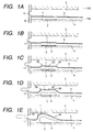
- Figs. 1A, 1B, 1C, 1D and 1E are cross sections of the directions of flow path depicted to aid in the description of the first example of the method for liquid discharge applicable to the present invention.
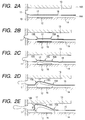
- Figs. 2A, 2B, 2C, 2D and 2E are cross sections of the direction of flow path depicted to aid in the description of the second example of the method for liquid discharge applicable to the present invention.
- Figs. 4A, 4B, 4C and 4D are model diagrams of cross section of direction of flow path for illustrating the first example of the liquid discharge head of the present invention.
- Fig. 5 is a perspective view of the liquid discharge head shown in Figs. 4A to 4D.
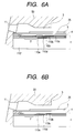
- Figs. 6A and 6B are longitudinal sections illustrating an example of the structure of a liquid discharge heat; Fig. 6A representing a head furnished with a protective membrane and Fig. 6B representing a head devoid of a protective membrane.
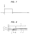
- Fig. 8 is a diagram illustrating the state of union between a movable separation membrane and a movable member.
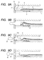
- Figs. 9A, 9B, 9C and 9D are model diagrams of cross section of direction of flow path for illustrating the second example of the liquid discharge head of the present invention.
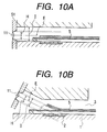
- Figs. 10A and 10B are diagrams illustrating the projected region of a discharge port of the liquid discharge head.
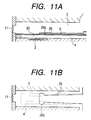
- Figs. 11A and 11B are model diagrams of cross section of direction of flow path for illustrating the third example of the liquid discharge head of the present invention.
- Fig. 12 is a model diagram illustrating an example of the structure of the liquid discharge head of this invention.
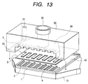
- Fig. 13 is an exploded perspective view illustrating an example of the structure of the liquid discharge head of this invention.
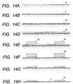
- Figs. 14A, 14B, 14C, 14D, 14E, 14F, 14G, and 14H are diagrams to aid in the description of a process for the manufacture of a movable separation membrane in the liquid discharge head of this invention.
- Figs. 15A and 15B are model diagrams of cross section of the direction of liquid flow illustrating the mode of the second embodiment of the liquid discharge head of this invention.
- FIGs. 1A to 1E, 2A to 2E and 3A to 3C are diagrams depicted to aid in the description of examples of the method for discharge of liquid which are applicable to the present invention.
- a discharge port is disposed in the terminal area of a first flow path. On the upstream side of the discharge port (relative to the direction of flow of a discharging liquid in the first flow path), the displacing region of a movable separation membrane capable of being displaced in accordance as the bubbles generated are grown.
- a second flow path is adapted to store a bubbling liquid or is filled with the bubbling liquid (preferably adapted to permit refill or allow the bubbling liquid to produce a motion) and is furnished with a bubble generating region.
- the bubble generating region is located on the upstream area from the discharge port side relative to the direction of flow of the discharging liquid mentioned above.
- the separation membrane is allowed to have a greater length than an electrothermal conversion element forming the bubble generating region and is consequently endowed with a movable region.
- a stationary part (not shown) is provided between the upstream side terminal part of the electrothermal conversion element and the common liquid chamber of the first flow path relative to the direction of flow mentioned above, preferably in the upstream side terminal part mentioned above.
- the state of the movable separation membrane depicted in these diagrams represents all the elements such as the elasticity and thickness of the movable separation membrane itself or the factors derivable from other additional structures.
- a first flow path 3 which directly communicates with a discharge port 11 is filled with the first liquid which is supplied from a common liquid chamber 143 and a second flow path 4 provided with a bubble generating region 7 is filled with a bubbling liquid which generates a bubble upon application of a thermal energy given by a heating element 2.
- a movable separation membrane 5 for separating the first flow path 3 and the second flow path 4 from each other is disposed between the first flow path 3 and the second flow path 4.
- the movable separation membrane 5 and an orifice plate 9 are tightly fixed to each other and they do not suffer the liquids in the two flow paths to mingle with each other.
- the movable separation membrane 5 generally manifests no directional property while it is being displaced by the bubbles generated in the bubble generating region 7. Rather, there are times when this displacement possibly proceeds toward the common liquid chamber side which enjoys high freedom of displacement.
- This example which has stemmed from the particular notice directed to this motion of the movable separation membrane 5, contemplates providing a device for controlling the direction of the displacement which directly or indirectly acts on the movable separation membrane 5 itself.
- This device is adapted to cause the displacement (motion, expansion, elongation, etc.) produced in the movable separation membrane 5 by the bubbles to proceed in the direction of the discharge port.
- the liquid in the first flow path 3 is drawn in closely to the discharge port 11 by the capillary force.
- the discharge port 11 is located on the downstream side relative to the direction of flow of the liquid in the first flow path 3 with respect to the area in which the heating element 2 is projected to the first flow path 3.
- the heating element 2 when the thermal energy is applied to the heating element 2 (a heating resistor measuring 40 ⁇ m ⁇ 105 ⁇ m, in the present mode), the heating element 2 is quickly heated and the surface of the bubble generating region 7 contacting the second liquid causes the second liquid to be bubbled by the heat (Fig. 1B).
- the bubbles 6 thus generated by the heating are based on such a phenomenon of membrane boiling as is disclosed in U.S. Patent No. 4,723,129. They are generated as accompanied by extremely high pressure all at once throughout the entire surface of the heating element.
- the pressure generated at this time propagates in the form of pressure wave through the second liquid in the second flow path 4 and acts on the movable separation membrane 5, with the result that the movable separation membrane 5 will be displaced and the discharge of the first liquid in the first flow path 3 will be started.
- the efficiency of discharge is further improved owing to the incorporation of the step for effecting the displacement of the movable separation membrane 5 in the direction of discharge on the downstream side so as to allow direct motion of the liquid in the direction of the discharge port as described above.
- the fact that the motion of the liquid toward the upstream side is decreased relatively brings about a favorable effect on the refill of the liquid (replenished from the upstream side) in the nozzle, specifically the displacing region of the movable separation membrane 5.
- Figs. 2A to 2E are cross sections of the direction of flow path depicted to aid in the description of the second example of the method for discharge of liquid which are applicable to the present invention (wherein the step of displacement contemplated by this invention starts from the initial stage).
- a first flow path 13 which directly communicates with the discharge port 11 is filled with the first liquid supplied from the first common liquid chamber 143 and a second flow path 14 furnished with a bubble generating region 17 is filled with a bubbling liquid which emits bubbles on exposure to a thermal energy supplied by a heating element 12.
- a movable separation membrane 15 adapted to separate the first flow path 13 and the second flow path 14 from each other is interposed between the first flow path 13 and the second flow path 14.
- the movable separation membrane 15 and an orifice plate 19 are tightly fixed to each other and they do not suffer the liquids in the two flow paths to mingle with each other.
- the liquid in the first flow path 13 is drawn in closely to the discharge port 11 by the capillary force.
- the discharge port 11 is located on the downstream side relative to the area in which the heating element 12 is projected to the first flow path 13.
- the heating element 12 when the thermal energy is given to the heating element 12 (a heating resistor measuring 40 ⁇ m ⁇ 115 ⁇ m, in the present mode), the heating element 12 is quickly heated and the surface of the bubble generating region 17 contacting the second liquid causes the second liquid to be bubbled by the heat (Fig. 2B).
- the bubbles 16 thus generated by the heating are based on such a phenomenon of membrane boiling as is disclosed in U.S. Patent No. 4,723,129. They are generated as accompanied by extremely high pressure all at once throughout the entire surface of the heating element.
- the pressure generated at this time propagates in the form of pressure wave through the second liquid in the second flow path 14 and acts on the movable separation membrane 15, with the result that the movable separation membrane 15 will be displaced and the discharge of the first liquid in the first flow path 13 will be started.
- the bubbles 16 generated on the entire surface of the heating element 12 grow quickly, they eventually assume the shape of a membrane (Fig. 2C).
- the expansion of the bubbles 16 by the very high pressure in the nascent state further adds to the displacement of the movable separation membrane 15 and, as a result, promotes the discharge of the first liquid in the first flow path 13 through the discharge port 11.
- the movable separation membrane 15 has the downstream side part 15B of the movable region thereof displaced rather more than the upstream side part 15A thereof from the initial stage as illustrated in Fig. 2C.
- the first liquid in the first flow path 13, therefore, is moved to the discharge port 11 with high efficiency from the initial stage.
- the displacement of the movable separation membrane 15 is proportionately enlarged (Fig. 2D) because the displacement of the movable separation membrane 15 and the growth of the bubbles are promoted relative to the state illustrated in Fig. 2C.
- the downstream side part 15B of the movable region is displaced more largely in the direction of the discharge port than the upstream side part 15A and the central part 15C, the first liquid in the first flow path 13 directly moves with acceleration in the direction of the discharge port. Since the displacement of the upstream side part 15A is small throughout the entire process, the motion of the liquid in the upstream direction is diminished.
- the method of liquid discharge in this example therefore, can improve the discharge efficiency, especially the discharge speed and further can favorably stabilize the refill of the liquid in the nozzle and the volume of the discharged liquid drops.
- the downstream side part 15B and the central part 15C of the movable separation membrane 15 are further displaced and elongated in the direction of the discharge port to promote the effect mentioned above, namely the improvement of the discharge efficiency and the discharge speed (Fig. 2E).
- the shape of the movable separation membrane 15 in this case is enlarged not only in the cross section but also in the sizes of displacement and elongation in the direction of width of the flow path, the operating region for moving the first liquid in the first flow path 13 is increased and the discharge efficiency is synergistically improved. Since the shape of the displacement of the movable separation membrane 15 at this time resembles the shape of a human nose, it will be particularly referred to as "nose shape".
- the nose shape is to be construed as embracing the shape of the latter "S" in which the point B located on the upstream side in the initial state assumes a position on the downstream side from the point A located on the downstream side in the initial state as illustrated in Fig. 2E and the shape in which the points A and B assume equivalent positions as illustrated in Fig. 1E.
- Figs. 3A to 3C are cross sections of a direction of flow path depicted to aid in the description of the step of displacement of the movable separation membrane in the method of liquid discharge according to this invention.
- the method using the structure illustrated in Fig. 3A incorporates therein from the initial stage a step of displacing a movable separation membrane 25 from the initial state sequentially in the order of (1), (2), and (3) and more largely on the downstream side than the upstream side and particularly succeeds in improving the discharge speed because it operates to exalt the discharge efficiency and, at the same time, enable the displacement on the downstream side to impart to the first liquid in the first flow path 23 such a motion as to be forced out in the direction of the discharge port.
- the movable range mentioned above is assumed to be substantially fixed.
- the movable range of the movable separation membrane 25 is shifted or enlarged toward the discharge port in accordance as the movable separation membrane 25 is displaced sequentially in the order of (1), (2), and (3) in the diagram.
- the movable range mentioned above has the upstream side thereof fixed.
- the discharge efficiency can be further exalted here because the movable separation membrane 25 is displaced more largely on the downstream side than on the upstream side thereof and because the bubbles are grown in the direction of the discharge port.
- the methods of liquid discharge which incorporate therein such steps as described above are applicable to the present invention.
- the components illustrated in Figs. 3A to 3C do not always function independently of each other.
- the steps which incorporate such components therein are likewise applicable to this invention.
- the step which involves the formation of the nose shape is not limited to the structure illustrated in Fig. 3C. It can be incorporated in the structures illustrated in Figs. 3A and 3B.
- the movable separation membrane used in the structure of Figs. 3A to 3C the possession of expansibility does not matter and the preparatory impartation of slackness suffices.
- the thickness of the movable separation membrane appearing in the diagram has no dimensional significance.
- the expression "device for controlling direction” as used in the present specification applies to at least one of all the members (means) which bring about the "displacement” specified by the present invention, such as, for example, those stemming from the structure or characteristic of the movable separation membrane itself, those pertaining to the operation or disposition of the bubble generating device with respect to the movable separation membrane, those relating to the fluid resistance offered by the vicinity of the bubble generating region, those acting directly or indirectly on the movable separation membrane, or those effecting control of the displacement or elongation of the movable separation membrane.
- the embodiments incorporating a plurality (two or more) of such direction controlling devices as mentioned above, therefore, are naturally embraced by the present invention.
- the examples which will be cited herein below make no definite mention of arbitrary combination of a plurality of direction-controlling devices. This notwithstanding, the present invention does not need to be limited to the following examples.
- the present liquid discharge head causes generation of bubbles in a bubble generating region 30 of the second flow path 4 near the heating element 2 (40 ⁇ 105 ⁇ m, for example) because this heating element 2 which is disposed on the device substrate 1 heats the liquid in the bubble generating region 30 and induces membrane boiling as illustrated in Fig. 4A.
- This region and the first flow path 3 communicating with the discharge port 11 are substantially separated from each other by the movable separation membrane 5 and, consequently, the liquid of the first flow path 3 and that of the second flow path 4 are not suffered to mingle with each other.
- These liquids of the first and the second flow path 3 and 4 may be the same or different, depending on the purpose of use.
- a movable member 26 having a free end provided on the discharge port side is disposed opposite the displacement region of the movable separation membrane 5 which is displaced by the bubbles generated in the bubble generating region 30.
- the free end is preferred to be positioned on the discharge port side from the center F of the area of the heating element 2 for the sake of the movable member 26 itself.
- the bubble 40 generated by the heating element 2 has grown to the substantially largest volume but the displacement region of the movable separation membrane 5 as a whole has displaced and elongated toward the discharge port because the directions of displacement and elongation of the movable separation membrane 5 are regulated by the movable member 26.
- the displacement and elongation toward the discharge port is accomplished more effectively because the free end of the movable member 26 is disposed on the discharge port side from the center F of the area of the heating element 2 as described above and the displacement region of the movable separation membrane 5 can be regulated substantially wholly.
- main drops (liquid drops) 32 separate more quickly from the liquid in the flow path 3 because the movable member 26, by virtue of the resiliency thereof, functions so as to accelerate the contraction of the movable separation membrane 5 and tends to draw meniscuses 31a and 31b quickly through the discharge port 11 into the flow path 3.
- satellites 33 illustrated in Fig. 4D are compelled to lose length and volume as well.
- the produced images therefore, contain such satellite only sparingly and enjoy both sharpness and quality.
- the ink contains mist only sparingly, it scarcely smears the face and the interior of the printer and adds markedly to the reliability of printing.
- the balance of shape between the meniscuses 31a and 31b affects the direction of the satellites 33.
- the tilt manifests itself as a deviation of the accuracy of impingement of liquid drops on a recording medium.
- the lost balance also causes a deviation of impingement due to the difference of direction of the discharge of the main drops 32 and the satellites 33. The consequence is a so-called satellite print which impairs the quality of image.
- the speed of contraction of the movable separation membrane 5 is heightened by the resiliency on the opposite side than on the discharge port side, namely the contraction speed V A of the movable separation membrane 5 on the upstream side (the side opposite the discharge port) of the movable region is heightened than the contraction speed V B thereof on the downstream side (the discharge port side) to satisfy the relation, V B ⁇ V A , with the result that the flow speed B on the side nearer to the movable separation membrane 5 will be restrained from increasing excessively, the flow speed A on the side offering greater resistance to flow will be heightened, and the simultaneous control of the two flow speeds A and B will be realized.
- the meniscuses 31a and 31b therefore, are symmetralized in shape relative to the center line E of the nozzle and the direction of the satellites 33 is equalized to that of the main drops 32.
- the efficiency of supply of liquid from the upstream side can be exalted, the refill property improved, and the drive speed increased by heightening the speed of contraction of the movable separation membrane 5 on the upstream side.
- Fig. 5 is a perspective view of the liquid discharge head of Figs. 4A to 4D, illustrating substantially the same state as Fig. 4B.
- an electric current is fed by a wiring 34 to the heating element 2 as an electric resistor.
- the structure of the device substrate 1 which is provided with the heating element 2 fulfilling the role of imparting heat to the liquid will be explained below.
- Figs. 6A and 6B are longitudinal sections illustrating an example of the structure of the liquid discharge heat according to this invention; Fig. 6A representing a head furnished with a protective membrane which will be described specifically herein below and Fig. 6B representing a head devoid of an anti-cavitation layer as a protective membrane.
- the device substrate 1 seats a second flow path 4, a movable separation membrane 5 destined to form a separation wall, a movable member 26, a first flow path 3, and a grooved member 50 furnished with a groove for forming the first flow path 3.
- a silicon oxide film or silicon nitride film 110e aiming to offer insulation and storage of heat is formed on a base body 110f of silicon, for example, and an electric resistance layer 110d, 0.01 to 0.2 ⁇ m in thickness, of hafnium boride (HfB 2 ), tantalum nitride (TaN), or tantalum aluminum (TaAl), for example, intended to form a heating element and two wiring electrodes 110c, 0.2 to 1.0 ⁇ m in thickness, of aluminum, for example, are superposed thereon by patterning.
- HfB 2 hafnium boride
- TaN tantalum nitride
- TaAl tantalum aluminum
- the electric resistance layer 110d is incited to emit heat by applying a voltage from the two wiring electrode 110c to the electric resistance layer 110d thereby causing supply of an electric current to the electric resistance layer 110d.
- a protective layer 110b On the electric resistance layer 110d intervening between the wiring electrodes 110c, a protective layer 110b, 0.1 to 0.2 ⁇ m in thickness, of silicon oxide or silicon nitride, for example, is formed and an anti-cavitation layer 110a, 0.1 to 0.6 ⁇ m in thickness, of tantalum, for example, is further superposed thereon to protect the electric resistance layer 110d from various liquid such as ink.
- Ta tantalum
- the discharge head may be formed in such a structure by suitably combining liquids, flow path layouts, and resistance materials as obviates the anti-cavitation layer as a protective layer.
- a structure is illustrated in Fig. 6B.
- An iridium-tantalum-aluminum alloy for example, may be cited as a material for the electric resistance layer which has no use for a protective layer.
- the absence of the protective layer proves to be rather advantageous because the bubbling liquid is rendered fit for bubble generating by being separated from the discharging liquid.
- the structure of the heating element 2 in the mode of the embodiment described above is only required to have the electric resistance layer 110d (heating element) interposed between the wiring electrodes 110c. It may otherwise incorporate therein the protective layer 110b for protecting the electric resistance layer 110d.
- the present example has been depicted as adopting for the heating element 2 a heating element formed of a resistance layer which is capable of emitting heat in response to an electric signal.
- This invention does not need to limit the heating element 2 to this particular structure but only requires it to be capable of producing in the bubbling liquid such bubbles as are necessary for causing discharge of the discharging liquid.
- the heating element such a photothermal converting device as emits heat on receiving the light like a laser beam or a heating device furnished with such a heating element as emits heat on receiving a high frequency may be adopted, for example.
- the element substrate 1 mentioned above is allowed to have such functional elements as transistors, diodes, latches, and shift registers which are used for selectively driving the electrothermal conversion elements integrally incorporated therein during the process of semiconductor production.
- the resistance layer 110d interposed between the wiring electrodes is incited to generate heat promptly by applying a rectangular pulse to the electric resistance layer 110d via the wiring electrode 110c.
- Fig. 7 is a diagram depicting the voltage waveform to be applied to the heating element 2 in the form of an electric resistance layer illustrated in Figs. 6A and 6B.
- the heating element is set driving by the application thereto of an electric signal at 6 kHz under the conditions of 24 V of voltage, 7 ⁇ sec of pulse width, and 150 mA of electric current and, in consequence of the operation performed as described above, an ink as a liquid wished to be discharged is discharged through the discharge port.
- the conditions for the drive signal in this invention do not need to be limited to those mentioned above.
- the drive signal is only required to be capable of causing the bubbling liquid to bubble generating perfectly.
- the movable separation membrane 5 and the movable 26 are so constructed as to adhere fast to each other while the bubbles 40 are in the process of contraction as described above.
- Fig. 8 which corresponds to Fig. 4D.
- the movable separation membrane 5 is joined to the free end side of the movable member 26 at the adhesive part 26a thereof. Owing to this union, the movable separation membrane 5 is restrained by the rigidity of the movable member 26 from being displaced toward the second flow path by the contraction of the bubbles 40.
- the directionality of satellites described in the preceding example can be improved, the amount of satellite decreased to the extent of improving the print in quality, and the refill property exalted without suffering the large displacement of the movable separation membrane 5 toward the second flow path to add to the amount of retraction of meniscuses.
- Figs. 9A to 9D and Figs. 10A and 10B are model diagrams of cross section in the direction of flow of liquid, illustrating the second example of the liquid discharge head of this invention.
- Fig. 9A illustrates the state of the liquid discharge head during the absence of discharge of liquid
- Fig. 9B to Fig. 9D illustrate the state thereof in the presence of liquid discharge.
- the leading terminal part of the movable separation membrane 5 is positioned below the lower part of the discharge port 11 so as to contact or approximate closely to an orifice plate 51. In the present example, it is disposed such that at least part of the displacement region of the movable separation membrane 5 in its initial state occurs in the substantial projected region H of the discharge port 11 along the center line E of the discharge port 11. The rest of the structure is the same as in the first example.
- This structure constitutes itself one example of decreasing the resistance of flow path and heightening the flow speed B when the effect of operating the movable member on the side farther from the movable separation membrane 4 and the flow speed A increases excessively and, consequently, attaining balanced control of the flow speeds A and B.
- the meniscuses 31a and 31b can be symmetrized in shape relative to the central line E of the discharge port 11 and the direction of the satellites can be equalized to that of the main drops 32.
- the projected region of the discharge port 11 along the central line E of the discharge port 11, as illustrated in Fig. 10A embraces the projected region 1 of the flow path side opening.
- Figs. 11A and 11B are model diagrams of cross section of the direction of flow path illustrating the third example of the liquid discharge head of this invention; Fig. 11A representing a cross section taken in the direction of flow path and Fig. 11B a plan view of the direction of flow path.
- the present example differs from the first example solely in respect that a lower displacement restraining part 26b capable of allowing the movable member 26 to have a greater width than the second flow path 4 is disposed near the free end of the movable member 26 and that the movable separation membrane 5 and the movable member 26 are joined fast to each other at the adhesive part 26a.
- the rest of the construction is the same as that of the first example.
- the lower displacement restraining part 26b mentioned above may be in such a structure as to effect partial repression of the displacement toward the second flow path 4 instead of causing the displacement toward the second flow path 4 completely as in the present example.
- Fig. 12 is a model diagram illustrating an example of the structure of the liquid discharge head of this invention.
- like component parts illustrated in Figs. 1A to 1E through Figs. 11A and 11B will be denoted by like reference numerals. These component parts will be omitted from the following specific description.
- the grooved member 50 in the liquid discharge head illustrated in Fig. 12 is roughly composed of the orifice plate 51, a plurality of grooves destined to form a plurality of first flow paths 3, and a recess destined to form a first common liquid chamber 48 communicating with the plurality of first flow paths 3 and supplying a liquid (discharging liquid) to the first flow paths 3.
- the plurality of first flow paths 3 are formed by joining the movable separation membrane 5 to the lower side part of this grooved member 50.
- the grooved member 50 is furnished with a first liquid feeding path 20 extending from the upper part thereof to the interior of the first common liquid chamber 48 and a second liquid feeding path 21 extended from the upper part thereof to the interior of a second common liquid chamber 49 through the movable separation membrane 5.
- the movable member 26 joined tightly to the upper side of the movable separation membrane 5 mentioned above is disposed to confront the bubble generating region 30 with the free end thereof pointed in the direction of the discharge port.
- the free end of the movable member is positioned on the discharge port side relative to the center of the area of the heating element 2.
- the first liquid (discharging liquid) is supplied via the first liquid feeding path 20 and the first common liquid chamber 48 to the first flow path 3 as indicated by an arrow mark C in Fig. 12 and the second liquid (bubbling liquid) is supplied via the second fluid feeding path 21 and the second common liquid chamber 49 to the second flow path 4 as indicated by an arrow mark D in Fig. 12.
- the present example is depicted as disposing the second liquid feeding path 21 and the first liquid feeding path 20 parallelly to each other, the present invention does not need to use these paths in this particular layout. They may be incorporated in any arbitrary layout so long as they penetrate the movable separation membrane 5 disposed outside the first common liquid chamber 48 and communicate with the second common liquid chamber 49.
- the thickness (diameter) of the second liquid feeding path 21 is fixed in consideration of the amount of the second liquid to be supplied.
- the cross section of the second liquid feeding path 21 does not need to be a circle but may be a rectangle, for example.
- the second common liquid chamber 49 can be formed by properly partitioning the grooved member 50 with the movable separation membrane 5.
- the second common liquid chamber 49 and the second flow path 4 may be constructed, for example, by forming a common liquid chamber frame and a second flow path wall with a dry film on the device substrate 1 and then pasting to the device substrate 1 the union obtained by combining the movable separation membrane 5 with the grooved member 50 fixing the movable separation membrane 5 in position.
- Fig. 13 is an exploded perspective view illustrating one example of the structure of the liquid discharge head of this invention.
- the device substrate 1 furnished with a plurality of electrothermal conversion elements, i.e. heating elements 2 for generating the heat necessary for the generation of bubbles in the bubbling liquid by membrane boiling as described above is formed on a supporting member 70 which is formed of such metal as aluminum.
- a plurality of grooves destined to form second flow paths 4 defined by second flow path walls, a recess for forming the second common liquid chamber (common bubbling liquid chamber) 49 communicating with a plurality of second flow paths 4 and feeding the bubbling liquid severally to the second flow paths 4, and the movable separation membrane 5 furnished with the movable member 26 are provided.
- the grooved member 50 is provided with a groove adapted to form the first flow path (discharging liquid flow path) 3 in combination with the movable separation membrane 5, a recess for forming the first common liquid chambers (common discharging liquid chambers) 48 communicating with the discharging liquid flow path and supplying the discharging liquid severally to the first flow paths 3, the first liquid feeding path (discharging liquid feeding path) 20 for supplying the discharging liquid to the first common liquid chambers 48, and the second liquid feeding path (bubbling liquid feeding path) 21 for supplying the bubbling liquid to the second common liquid chamber 49.
- the second liquid feeding path 21 is connected to the communicating path which penetrates the movable separation membrane 5 disposed outside the first common liquid chamber 48 and communicates with the second common liquid chamber 49 and, owing to this communicating path, is enabled to supply the bubbling liquid to the second common liquid chamber 48 without being mixed with the discharging liquid.
- the movable member 26 is disposed correspondingly to the heating element 2 of the device substrate 1 and the first flow path 3 is disposed correspondingly to the movable member 26.
- the present embodiment is depicted as having the second liquid feeding path 21 disposed on one grooved member 60, this invention allows incorporation of a plurality of such second liquid feeding paths 21 depending on the amount of the relevant liquid to be supplied.
- the cross-sectional areas of the first liquid feeding path 20 and the second liquid feeding path 21 may be fixed proportionately to the amounts of liquid to be supplied.
- the component parts of the grooved member 50 can be miniaturized by optimizing these cross-sectional areas.
- the number of component parts can be decreased, the process of operation shortened, and the cost of operation cut by the fact that the second liquid feeding path 21 for supplying the second liquid to the second flow path 4 and the first liquid feeding path 20 for supplying the first liquid to the first flow path 3 are formed of one same grooved top plate as the grooved member 50 as described above.
- the supply of the second liquid to the second common liquid chamber 49 which communicates with the second flow path 4 is accomplished by means of the second flow path in the direction of piercing the movable separation membrane 5 which separates the first and the second liquid from each other. Since the process of pasting the movable separation membrane 5 and the grooved member 50 to the device substrate 1 having formed therein the heating element 2, therefore, can be performed all at once, the ease of manufacture is exalted, the accuracy of union by pasting improved, and the discharge of liquid attained satisfactorily.
- the supply of the second liquid to the second flow path 4 is effected infallibly because the second liquid is supplied through the movable separation membrane 5 to the second common liquid chamber 49.
- the discharge of liquid, therefore, is stabilized because the supply is amply secured.
- the liquid discharge head of this invention causes discharge of liquid with high discharging force and high discharge efficiency and quickly as compared with the conventional liquid discharge head.
- the bubbling liquid to be used may be a liquid of such quality as specified above.
- a varying liquid may be used without reference to bubble generation properties and thermal properties. Even a liquid of poor bubble generation properties, a liquid readily degenerated or deteriorated by heat, or a liquid of unduly high viscosity which has not been easily discharged by the conventional discharge head can be effectively utilized.
- the discharging liquid to be used herein is preferred to avoid interfering with the action of discharging or bubble generating or with the operation of the movable separation membrane or the movable member owing to the reaction of its own or with the bubbling liquid.
- a highly viscous ink may be utilized.
- Bubbling liquids and discharging liquids of the following compositions were used in varying combinations to effect discharge of the discharging liquids and produce records.
- a review of the records reveals that not only liquids of a viscosity of ten-odd cp which were not easily discharged with the conventional head but also liquids of such very high viscosity as 150 cp could be discharged satisfactorily to produce records of high image quality.
- the manufacture of the head was effected by forming the wall of a second flow path on the device substrate, fitting thereon the movable separation membrane furnished with the movable member, and fitting further thereon the grooved member containing a groove for forming the first flow path. Otherwise, it was attained by forming the wall of the second flow path and then joining onto the wall the grooved member having fitted thereto the movable separation membrane furnished with the movable member.
- the electrothermal conversion element furnished with the heating element made of hafnium boride or tantalum nitride was formed on the device substrate (silicon wafer) by the use of the same device of manufacture as that used for a semiconductor and then the surface of the device substrate was cleaned for the purpose of improving the tight adhesion of the surface to a photosensitive resin in the subsequent step.
- the surface of the device substrate it suffices to subject the surface of the device substrate to a treatment with ultraviolet light and oregion and then apply to the treated surface by spin coating a solution obtained by diluting a silane coupling agent (made by Nihon Unica K.K. and sold under the product code of "A189”) to a concentration of 1 wt. % with ethyl alcohol.
- a photomask PM was laid on the dry film DF and the portion of the dry film DF required to remain as a second flow path wall was exposed to the ultraviolet light through the photomask PM.
- This step of exposure was effected by the use of an instrument (made by Canon Inc. and sold under the product code of "MPA-600") with an exposure of about 600 mJ/cm 2 .
- the dry film DF was then developed with a developer (made by Tokyo Ohka K.K. and sold under the product code of "BMRC-3") formed of a mixture of xylene with butyl cellosolve acetate to dissolve out the unexposed part and obtain the exposed and hardened part as the wall part of the second flow path 4.
- the residue still persisting on the surface of the device substrate 1 was removed by about 90 seconds' treatment with a plasma ashing device (produced by Arukantec Inc. and sold under the product code of "MAS-800").
- the substrate was subsequently exposed to the ultraviolet light projected at a rate of 100 mJ/cm 2 at 150°C for two hours to harden perfectly the exposed part.
- the second flow paths could be formed with high precision uniformly on a plurality of heater boards (device substrates) fabricated as cut from the silicon substrate by the method described above. Specifically, the silicon substrate was cut into the individual heater boards 1 with the dicing machine (made by Tokyo Seimitsu K.K. and sold under the product code of "AWD-4000") fitted with a diamond plate, 0.05 mm in thickness. The separated heater boards 1 were fixed with an adhesive agent (made by Toray Industries, Inc. and sold under the product code of "SE4400”) on an aluminum base plate.
- the dicing machine made by Tokyo Seimitsu K.K. and sold under the product code of "AWD-4000
- the separated heater boards 1 were fixed with an adhesive agent (made by Toray Industries, Inc. and sold under the product code of "SE4400”) on an aluminum base plate.
- the print substrate joined in advance to the aluminum base plate and connected to the heater boards with an aluminum wire, 0.05 mm in diameter.
- the flow paths can be obtained with high precision without any positional deviation from the heaters of the heater boards mentioned above.
- the positional precision of the first flow paths and the movable members can be exalted.
- the high-precision production technique described above stabilizes the discharge of liquid and improves the quality of print. Further, the fact that the component parts are formed collectively on the wafer permits quantity production of the liquid discharge heads at a low cost.
- the present mode of embodiment has been depicted as using an ultraviolet hardening type dry film for the formation of the second flow paths.
- the formation of the second flow paths may be attained by adopting a resin having an absorption band near the ultraviolet region, particularly a region of 248 nm, laminating the resin, hardening the resultant laminate, and directly removing the part of the laminate wished to form the second flow path with an excimer laser.
- Figs. 14A to 14H are diagrams depicted to aid in the description of the process of manufacturing the movable separation membrane in the liquid discharge head according to this invention.
- a mold release agent is applied on a mirror wafer (silicon wafer) 35 of silicon as illustrated in Fig. 14A.
- a liquid polyimide resin destined to form the movable separation membrane is deposited by spin coating to form a film (movable separation membrane) 5, about 3 ⁇ m in thickness, as illustrated in Fig. 14B.
- a metal thin film 36 is deposited as by sputtering in a thickness of 0.1 ⁇ m as illustrated in Fig. 14C.
- This metal thin film 36 is coated with a film, about 5 ⁇ m in thickness, as by plating as illustrated in Fig. 14D.
- a pattern of resist 38 is formed on the last formed film.
- the one-piece unit composed of the movable separation membrane and the movable member is peeled off the silicon wafer 35 as illustrated in Fig. 14H.
- Figs. 15A and 15B are model diagrams of cross section of the direction of flow path illustrating the mode of the second embodiment of the liquid discharge head according to this invention; Fig. 15A representing the state of the liquid discharge head during the absence of liquid discharge and Fig. 15B the state thereof during the presence of liquid discharge.
- slack parts 28a and 28b are disposed respectively in the former and the latter part of the movable separation membrane 28. Since the pressure generated by the formation of bubbles extends the slack parts 28a and 28b, the volume of the bubbles 40 can be effectively utilized for the deformation of the movable separation membrane 28. The discharging force of greater magnitude can be attained more efficiently, therefore, because the movable member 26 is displaced more largely toward the first flow path 3 consequently.
- the direction of the slack parts 28a and 28b imposes no specific restriction because the pressure generated in consequence of the formation of bubbles is only required to expand the slack parts 28a and 28b in the direction of the discharge port.
- the rest of the structure is identical with the structure involved in the mode of the first embodiment.
- the movable separation membrane 28 is enabled to acquire an exalted discharge efficiency by being furnished with such slack parts as mentioned above.
- the present example does not require the membrane itself to possess expansibility.
- the movable separation membrane 28 is formed in a uniform thickness by the same procedure as in the mode of the first embodiment described above.
- the movable member 26 is manufactured by electrically casting nickel.
- the method of manufacture by the electrical casting of nickel comprises applying a resist on a substrate of SUS in a thickness of 5 ⁇ m and then patterning the deposited resist in the shape of a row of continued comb teeth so as to facilitate the assemblage of a plurality of movable members adapted to correspond to the flow paths and continue within the common liquid chambers.
- the SUS substrate is electrically plated with a nickel layer, again 3 ⁇ m in thickness.
- the plating liquid used in this case is composed of nickel sulfofmate, a stress allaying agent (made by World Metal K.K. and sold under the trademark designation of "Zeroall"), boric acid, a bit preventive (made by World Metal K.K. and sold under the product code of "NP-APS"), and nickel chloride.
- the application of an electric field in the electrodeposition is effected by setting a relevant electrode on the anode side, fitting the patterned SUS substrate on the cathode side, keeping the plating liquid at a temperature of 50°C, and fixing the current density at 5A/cm 2 .
- the SUS substrate After the SUS substrate has been plated as described above, it is deprived of the part of nickel layer by exposure to an ultrasonic oscillation. Consequently, the movable member wished to be obtained is produced.
- a heater board having electrothermal conversion elements superposed thereon is formed on a silicon wafer by the use of the same facility as normally used for a semiconductor.
- the second bubbling liquid flow path is formed in advance as with dry film similarly in the mode of the first embodiment described above.
- the wafer is separated into individual heater boards with a dicing machine.
- the heater board is joined to an aluminum base plate to which a printed substrate has been joined preparatorily and the printed substrate is connected to an aluminum wire to give rise to an electric wiring.
- the liquid discharge head aimed at is completed by pasting the movable separation membrane 28 on the heater board in the ensuant state, then aligning the movable member 26 manufactured by the procedure described above to the heating element 2 and joining them, then setting the grooved member in position and joining it to the other component parts already in plate with the aid of a retaining spring.
- the materials which are preferably used for the movable members include such metals as silver, nickel, gold, iron, titanium, aluminum, platinum, tantalum, stainless steel, and phosphor bronze which abound in durability and alloys of these metals, resins such as acrylonitrile, butadiene, and styrene which have a nitrile group, resins such as polyamides which have an amide group, resins such as polycarbonate which have a carboxyl group, resins such as polyacetal which have an aldehyde group, resins such as polysulfones which have a sulfone group, other resins such as liquid crystal polymers and compounds thereof, metals such as gold, tungsten, tantalum, nickel, stainless steel, and titanium which offer high resistance to inks, alloys of these metals, materials coated with these metals or alloys for the sake of resistance to inks, resins such as polyamides which have an amide group, resins such as polyacetals which have an alde
- the materials which are preferably used for the movable separation membranes include such engineering plastics of the recent development as, for example, polyethylene, polypropylene, polyamide, polyethylene terephthalate, melamine resins, phenol resins, polybutadiene, polyurethane, polyether ether ketone, polyether sulfones, polyarylate, silicone rubber, and polysulfones which excel in resistance to heat, resistance to solvents, and moldability, exhibit elasticity, and permit production of thin films, and compounds of the plastics in addition to the polyimides mentioned above.
- engineering plastics of the recent development as, for example, polyethylene, polypropylene, polyamide, polyethylene terephthalate, melamine resins, phenol resins, polybutadiene, polyurethane, polyether ether ketone, polyether sulfones, polyarylate, silicone rubber, and polysulfones which excel in resistance to heat, resistance to solvents, and moldability, exhibit elasticity, and permit production of
- the thickness of the movable separation membrane 28 may be decided in consideration of the material, shape, etc. of the membrane from the viewpoint of attaining the strength proper for any separation wall and producing the actions of expansion and contraction satisfactorily. Generally, this thickness is preferred to fall in the approximate range of 0.5 to 10 ⁇ m.
- this invention Since this invention is constructed as described above, it manifests the following effects. In the present example, part of the effect of this invention is attained even in the absence of elasticity because the slack pack 28a is used at the relevant portion.
- this invention owing to its principle, can be applied to the type of liquid discharge head which is provided with the discharge port at a position opposite the surface of the heating element.
Landscapes
- Particle Formation And Scattering Control In Inkjet Printers (AREA)
- Ink Jet (AREA)
Applications Claiming Priority (3)
| Application Number | Priority Date | Filing Date | Title |
|---|---|---|---|
| JP14938397A JP3416465B2 (ja) | 1997-06-06 | 1997-06-06 | 液体吐出方法及び液体吐出ヘッド |
| JP149383/97 | 1997-06-06 | ||
| JP14938397 | 1997-06-06 |
Publications (3)
| Publication Number | Publication Date |
|---|---|
| EP0882592A2 true EP0882592A2 (de) | 1998-12-09 |
| EP0882592A3 EP0882592A3 (de) | 1999-09-29 |
| EP0882592B1 EP0882592B1 (de) | 2005-09-07 |
Family
ID=15473935
Family Applications (1)
| Application Number | Title | Priority Date | Filing Date |
|---|---|---|---|
| EP98304454A Expired - Lifetime EP0882592B1 (de) | 1997-06-06 | 1998-06-05 | Verfahren zum Ausstossen von Flüssigkeit und Flüssigkeitsausstosskopf |
Country Status (8)
| Country | Link |
|---|---|
| US (1) | US6276783B1 (de) |
| EP (1) | EP0882592B1 (de) |
| JP (1) | JP3416465B2 (de) |
| KR (1) | KR100312948B1 (de) |
| AU (1) | AU6994298A (de) |
| CA (1) | CA2239640C (de) |
| DE (1) | DE69831442T2 (de) |
| TW (1) | TW372914B (de) |
Cited By (5)
| Publication number | Priority date | Publication date | Assignee | Title |
|---|---|---|---|---|
| US8696092B2 (en) | 2012-07-19 | 2014-04-15 | Eastman Kodak Company | Liquid dispenser including active membrane actuator |
| US8727501B2 (en) | 2012-07-19 | 2014-05-20 | Eastman Kodak Company | Membrane MEMS actuator with moving working fluid |
| US8733903B2 (en) | 2012-07-19 | 2014-05-27 | Eastman Kodak Company | Liquid dispenser including passive pre-stressed flexible membrane |
| US8757780B2 (en) | 2012-07-19 | 2014-06-24 | Eastman Kodak Company | Corrugated membrane MEMS actuator |
| US8835195B2 (en) | 2012-07-19 | 2014-09-16 | Eastman Kodak Company | Corrugated membrane MEMS actuator fabrication method |
Families Citing this family (9)
| Publication number | Priority date | Publication date | Assignee | Title |
|---|---|---|---|---|
| JP2003246076A (ja) * | 2002-02-22 | 2003-09-02 | Canon Inc | 液体貯蔵容器及びその製造方法 |
| US6880052B2 (en) * | 2002-03-26 | 2005-04-12 | Hewlett-Packard Development Company, Lp | Storage area network, data replication and storage controller, and method for replicating data using virtualized volumes |
| JP2004322530A (ja) * | 2003-04-25 | 2004-11-18 | Canon Inc | インクカートリッジ |
| US7207652B2 (en) * | 2003-10-17 | 2007-04-24 | Lexmark International, Inc. | Balanced satellite distributions |
| US7954930B2 (en) * | 2006-11-30 | 2011-06-07 | Fuji Xerox Co., Ltd. | Liquid droplet ejecting head and liquid droplet ejecting apparatus |
| DE102010063982B4 (de) * | 2010-12-22 | 2020-07-16 | Fraunhofer-Gesellschaft zur Förderung der angewandten Forschung e.V. | Verfahren und Vorrichtung zum Erzeugen einer dreidimensionalen Struktur auf einem Substrat |
| US9004651B2 (en) | 2013-09-06 | 2015-04-14 | Xerox Corporation | Thermo-pneumatic actuator working fluid layer |
| US9004652B2 (en) | 2013-09-06 | 2015-04-14 | Xerox Corporation | Thermo-pneumatic actuator fabricated using silicon-on-insulator (SOI) |
| US9096057B2 (en) | 2013-11-05 | 2015-08-04 | Xerox Corporation | Working fluids for high frequency elevated temperature thermo-pneumatic actuation |
Citations (6)
| Publication number | Priority date | Publication date | Assignee | Title |
|---|---|---|---|---|
| JPS5581172A (en) | 1978-12-14 | 1980-06-18 | Canon Inc | Liquid injection type recording method and device |
| JPS5926270A (ja) | 1982-07-30 | 1984-02-10 | Yokogawa Hewlett Packard Ltd | インクジエツト・プリンタ |
| JPS6159914B2 (de) | 1978-08-18 | 1986-12-18 | Canon Kk | |
| JPS6159911B2 (de) | 1977-10-03 | 1986-12-18 | Canon Kk | |
| JPH04329148A (ja) | 1991-04-30 | 1992-11-17 | Matsushita Electric Ind Co Ltd | インクジェットプリンタ |
| JPH05229122A (ja) | 1992-02-25 | 1993-09-07 | Seiko Instr Inc | インクジェットプリントヘッドおよびインクジェットプリントヘッドの駆動方法 |
Family Cites Families (16)
| Publication number | Priority date | Publication date | Assignee | Title |
|---|---|---|---|---|
| CA1127227A (en) | 1977-10-03 | 1982-07-06 | Ichiro Endo | Liquid jet recording process and apparatus therefor |
| JPS6159911A (ja) | 1984-08-30 | 1986-03-27 | Nec Corp | 切換スイツチ回路 |
| JPS6159914A (ja) | 1984-08-31 | 1986-03-27 | Fujitsu Ltd | デイジタル圧縮装置 |
| JPH01247168A (ja) | 1988-03-29 | 1989-10-03 | Toyota Autom Loom Works Ltd | インクジェットヘッド |
| US4994825A (en) | 1988-06-30 | 1991-02-19 | Canon Kabushiki Kaisha | Ink jet recording head equipped with a discharging opening forming member including a protruding portion and a recessed portion |
| US5208604A (en) | 1988-10-31 | 1993-05-04 | Canon Kabushiki Kaisha | Ink jet head and manufacturing method thereof, and ink jet apparatus with ink jet head |
| JPH02137930A (ja) | 1988-11-18 | 1990-05-28 | Nec Home Electron Ltd | インクジェット・ヘッド |
| DE69031666T2 (de) | 1989-01-13 | 1998-04-02 | Canon Kk | Tintenstrahlaufzeichnungskopf, Tintenstrahlaufzeichnungsgerät und Wischverfahren hierfür |
| ES2094746T3 (es) | 1989-09-18 | 1997-02-01 | Canon Kk | Aparato para chorros de tinta. |
| EP0461437B1 (de) | 1990-05-22 | 1998-07-29 | Canon Kabushiki Kaisha | Datenaufzeichnungsgerät |
| US5278585A (en) * | 1992-05-28 | 1994-01-11 | Xerox Corporation | Ink jet printhead with ink flow directing valves |
| JP3222593B2 (ja) | 1992-12-28 | 2001-10-29 | キヤノン株式会社 | インクジェット記録ヘッドおよびインクジェット記録ヘッド用モノリシック集積回路 |
| AU4092396A (en) | 1995-01-13 | 1996-08-08 | Canon Kabushiki Kaisha | Liquid ejecting head, liquid ejecting device and liquid ejecting method |
| TW332799B (en) | 1995-01-13 | 1998-06-01 | Canon Kk | The liquid ejecting head, device and method of liquid ejecting |
| US5821962A (en) * | 1995-06-02 | 1998-10-13 | Canon Kabushiki Kaisha | Liquid ejection apparatus and method |
| JP3542460B2 (ja) * | 1996-06-07 | 2004-07-14 | キヤノン株式会社 | 液体吐出方法及び液体吐出装置 |
-
1997
- 1997-06-06 JP JP14938397A patent/JP3416465B2/ja not_active Expired - Fee Related
-
1998
- 1998-06-03 TW TW087108741A patent/TW372914B/zh not_active IP Right Cessation
- 1998-06-03 US US09/089,254 patent/US6276783B1/en not_active Expired - Fee Related
- 1998-06-05 AU AU69942/98A patent/AU6994298A/en not_active Abandoned
- 1998-06-05 KR KR1019980020926A patent/KR100312948B1/ko not_active Expired - Fee Related
- 1998-06-05 CA CA002239640A patent/CA2239640C/en not_active Expired - Fee Related
- 1998-06-05 DE DE69831442T patent/DE69831442T2/de not_active Expired - Fee Related
- 1998-06-05 EP EP98304454A patent/EP0882592B1/de not_active Expired - Lifetime
Patent Citations (6)
| Publication number | Priority date | Publication date | Assignee | Title |
|---|---|---|---|---|
| JPS6159911B2 (de) | 1977-10-03 | 1986-12-18 | Canon Kk | |
| JPS6159914B2 (de) | 1978-08-18 | 1986-12-18 | Canon Kk | |
| JPS5581172A (en) | 1978-12-14 | 1980-06-18 | Canon Inc | Liquid injection type recording method and device |
| JPS5926270A (ja) | 1982-07-30 | 1984-02-10 | Yokogawa Hewlett Packard Ltd | インクジエツト・プリンタ |
| JPH04329148A (ja) | 1991-04-30 | 1992-11-17 | Matsushita Electric Ind Co Ltd | インクジェットプリンタ |
| JPH05229122A (ja) | 1992-02-25 | 1993-09-07 | Seiko Instr Inc | インクジェットプリントヘッドおよびインクジェットプリントヘッドの駆動方法 |
Cited By (5)
| Publication number | Priority date | Publication date | Assignee | Title |
|---|---|---|---|---|
| US8696092B2 (en) | 2012-07-19 | 2014-04-15 | Eastman Kodak Company | Liquid dispenser including active membrane actuator |
| US8727501B2 (en) | 2012-07-19 | 2014-05-20 | Eastman Kodak Company | Membrane MEMS actuator with moving working fluid |
| US8733903B2 (en) | 2012-07-19 | 2014-05-27 | Eastman Kodak Company | Liquid dispenser including passive pre-stressed flexible membrane |
| US8757780B2 (en) | 2012-07-19 | 2014-06-24 | Eastman Kodak Company | Corrugated membrane MEMS actuator |
| US8835195B2 (en) | 2012-07-19 | 2014-09-16 | Eastman Kodak Company | Corrugated membrane MEMS actuator fabrication method |
Also Published As
| Publication number | Publication date |
|---|---|
| DE69831442T2 (de) | 2006-03-16 |
| EP0882592B1 (de) | 2005-09-07 |
| EP0882592A3 (de) | 1999-09-29 |
| KR100312948B1 (ko) | 2002-04-17 |
| KR19990006714A (ko) | 1999-01-25 |
| AU6994298A (en) | 1998-12-10 |
| DE69831442D1 (de) | 2005-10-13 |
| CA2239640C (en) | 2005-03-29 |
| JP3416465B2 (ja) | 2003-06-16 |
| TW372914B (en) | 1999-11-01 |
| CA2239640A1 (en) | 1998-12-06 |
| JPH10337870A (ja) | 1998-12-22 |
| US6276783B1 (en) | 2001-08-21 |
Similar Documents
| Publication | Publication Date | Title |
|---|---|---|
| JP3542460B2 (ja) | 液体吐出方法及び液体吐出装置 | |
| EP0882592B1 (de) | Verfahren zum Ausstossen von Flüssigkeit und Flüssigkeitsausstosskopf | |
| JP3472030B2 (ja) | 液体吐出ヘッドの製造方法並びに液体吐出ヘッド、該液体吐出ヘッドを用いたヘッドカートリッジ、液体吐出装置及びヘッドキット | |
| US6450776B1 (en) | Liquid discharging head and liquid discharging method | |
| JP3408060B2 (ja) | 液体吐出方法および装置とこれらに用いられる液体吐出ヘッド | |
| EP0882890B1 (de) | Verfahren und Vorrichtung zum Zuführen von Flüssigkeit, Flüssigkeitsausstossverfahren und Flüssigeitsausstosskopf welche dieses Verfahren und Vorrichtung zum Zuführen von Flüssigkeit verwenden | |
| JP3372765B2 (ja) | 液体吐出ヘッド、ヘッドカートリッジ、液体吐出装置、記録システム、ヘッドキット、および液体吐出ヘッドの製造方法 | |
| US6302518B1 (en) | Liquid discharging head, liquid discharging apparatus and printing system | |
| CA2239762C (en) | Method for discharge of liquid and liquid discharge head | |
| AU2002300989B2 (en) | Method for Discharge of Liquid and Liquid Discharge Head | |
| JP3413063B2 (ja) | 液体吐出方法及び液体吐出ヘッド | |
| JPH1016243A (ja) | 液体吐出ヘッドの製造方法およびその製造方法により得られた液体吐出ヘッド | |
| MXPA98004377A (en) | Method for the discharge of liquid and head to download liquid | |
| JP3517526B2 (ja) | 液体吐出ヘッドおよび液体吐出装置 | |
| CA2174182C (en) | Method for producing liquid ejecting head and liquid ejecting head obtained by the same method | |
| MXPA98004375A (en) | Method for discharge liquid and liquid discharge head | |
| JP3710206B2 (ja) | 液体吐出ヘッド、液体吐出装置、および記録方法 | |
| JP2838868B2 (ja) | 液体噴射記録ヘッド | |
| JP3839875B2 (ja) | 液体吐出ヘッド、ヘッドカートリッジ及び液体吐出装置 | |
| JPH1148488A (ja) | 液体吐出ヘッドの製造方法及び液体吐出ヘッド | |
| JPH11348287A (ja) | 液体吐出ヘッド | |
| JPH1024578A (ja) | 液体吐出方法及び液体吐出ヘッド | |
| JPH0416355A (ja) | インク飛翔記録装置 | |
| JPH09323427A (ja) | 液体吐出ヘッドの製造方法および該製造方法により得られる液体吐出ヘッド |
Legal Events
| Date | Code | Title | Description |
|---|---|---|---|
| PUAI | Public reference made under article 153(3) epc to a published international application that has entered the european phase |
Free format text: ORIGINAL CODE: 0009012 |
|
| AK | Designated contracting states |
Kind code of ref document: A2 Designated state(s): DE ES FR GB IT NL |
|
| AX | Request for extension of the european patent |
Free format text: AL;LT;LV;MK;RO;SI |
|
| PUAL | Search report despatched |
Free format text: ORIGINAL CODE: 0009013 |
|
| AK | Designated contracting states |
Kind code of ref document: A3 Designated state(s): AT BE CH CY DE DK ES FI FR GB GR IE IT LI LU MC NL PT SE |
|
| AX | Request for extension of the european patent |
Free format text: AL;LT;LV;MK;RO;SI |
|
| 17P | Request for examination filed |
Effective date: 20000211 |
|
| AKX | Designation fees paid |
Free format text: DE ES FR GB IT NL |
|
| 17Q | First examination report despatched |
Effective date: 20020913 |
|
| GRAP | Despatch of communication of intention to grant a patent |
Free format text: ORIGINAL CODE: EPIDOSNIGR1 |
|
| GRAS | Grant fee paid |
Free format text: ORIGINAL CODE: EPIDOSNIGR3 |
|
| GRAA | (expected) grant |
Free format text: ORIGINAL CODE: 0009210 |
|
| AK | Designated contracting states |
Kind code of ref document: B1 Designated state(s): DE ES FR GB IT NL |
|
| PG25 | Lapsed in a contracting state [announced via postgrant information from national office to epo] |
Ref country code: NL Free format text: LAPSE BECAUSE OF FAILURE TO SUBMIT A TRANSLATION OF THE DESCRIPTION OR TO PAY THE FEE WITHIN THE PRESCRIBED TIME-LIMIT Effective date: 20050907 Ref country code: IT Free format text: LAPSE BECAUSE OF FAILURE TO SUBMIT A TRANSLATION OF THE DESCRIPTION OR TO PAY THE FEE WITHIN THE PRESCRIBED TIME-LIMIT;WARNING: LAPSES OF ITALIAN PATENTS WITH EFFECTIVE DATE BEFORE 2007 MAY HAVE OCCURRED AT ANY TIME BEFORE 2007. THE CORRECT EFFECTIVE DATE MAY BE DIFFERENT FROM THE ONE RECORDED. Effective date: 20050907 |
|
| REG | Reference to a national code |
Ref country code: GB Ref legal event code: FG4D |
|
| REF | Corresponds to: |
Ref document number: 69831442 Country of ref document: DE Date of ref document: 20051013 Kind code of ref document: P |
|
| PG25 | Lapsed in a contracting state [announced via postgrant information from national office to epo] |
Ref country code: ES Free format text: LAPSE BECAUSE OF FAILURE TO SUBMIT A TRANSLATION OF THE DESCRIPTION OR TO PAY THE FEE WITHIN THE PRESCRIBED TIME-LIMIT Effective date: 20051218 |
|
| NLV1 | Nl: lapsed or annulled due to failure to fulfill the requirements of art. 29p and 29m of the patents act | ||
| PLBE | No opposition filed within time limit |
Free format text: ORIGINAL CODE: 0009261 |
|
| STAA | Information on the status of an ep patent application or granted ep patent |
Free format text: STATUS: NO OPPOSITION FILED WITHIN TIME LIMIT |
|
| 26N | No opposition filed |
Effective date: 20060608 |
|
| PG25 | Lapsed in a contracting state [announced via postgrant information from national office to epo] |
Ref country code: FR Free format text: LAPSE BECAUSE OF FAILURE TO SUBMIT A TRANSLATION OF THE DESCRIPTION OR TO PAY THE FEE WITHIN THE PRESCRIBED TIME-LIMIT Effective date: 20061020 |
|
| EN | Fr: translation not filed | ||
| PGFP | Annual fee paid to national office [announced via postgrant information from national office to epo] |
Ref country code: DE Payment date: 20080630 Year of fee payment: 11 |
|
| PG25 | Lapsed in a contracting state [announced via postgrant information from national office to epo] |
Ref country code: FR Free format text: LAPSE BECAUSE OF FAILURE TO SUBMIT A TRANSLATION OF THE DESCRIPTION OR TO PAY THE FEE WITHIN THE PRESCRIBED TIME-LIMIT Effective date: 20050907 |
|
| PGFP | Annual fee paid to national office [announced via postgrant information from national office to epo] |
Ref country code: GB Payment date: 20080627 Year of fee payment: 11 |
|
| GBPC | Gb: european patent ceased through non-payment of renewal fee |
Effective date: 20090605 |
|
| PG25 | Lapsed in a contracting state [announced via postgrant information from national office to epo] |
Ref country code: GB Free format text: LAPSE BECAUSE OF NON-PAYMENT OF DUE FEES Effective date: 20090605 |
|
| PG25 | Lapsed in a contracting state [announced via postgrant information from national office to epo] |
Ref country code: DE Free format text: LAPSE BECAUSE OF NON-PAYMENT OF DUE FEES Effective date: 20100101 |