EP0882629A1 - Générateur de gaz - Google Patents
Générateur de gaz Download PDFInfo
- Publication number
- EP0882629A1 EP0882629A1 EP98110065A EP98110065A EP0882629A1 EP 0882629 A1 EP0882629 A1 EP 0882629A1 EP 98110065 A EP98110065 A EP 98110065A EP 98110065 A EP98110065 A EP 98110065A EP 0882629 A1 EP0882629 A1 EP 0882629A1
- Authority
- EP
- European Patent Office
- Prior art keywords
- gas generator
- gas
- chamber
- generator according
- combustion chamber
- Prior art date
- Legal status (The legal status is an assumption and is not a legal conclusion. Google has not performed a legal analysis and makes no representation as to the accuracy of the status listed.)
- Withdrawn
Links
- 238000002485 combustion reaction Methods 0.000 claims abstract description 22
- 239000007789 gas Substances 0.000 claims description 73
- 239000000446 fuel Substances 0.000 claims description 14
- 239000000463 material Substances 0.000 claims description 7
- 238000003466 welding Methods 0.000 claims description 6
- HSFWRNGVRCDJHI-UHFFFAOYSA-N Acetylene Chemical compound C#C HSFWRNGVRCDJHI-UHFFFAOYSA-N 0.000 claims 1
- 230000004913 activation Effects 0.000 claims 1
- 230000037452 priming Effects 0.000 claims 1
- 239000003380 propellant Substances 0.000 abstract 2
- 239000002245 particle Substances 0.000 description 5
- 238000007789 sealing Methods 0.000 description 2
- 238000010276 construction Methods 0.000 description 1
- 230000006378 damage Effects 0.000 description 1
- 238000004519 manufacturing process Methods 0.000 description 1
- 239000012528 membrane Substances 0.000 description 1
- 239000002184 metal Substances 0.000 description 1
Images
Classifications
-
- B—PERFORMING OPERATIONS; TRANSPORTING
- B60—VEHICLES IN GENERAL
- B60R—VEHICLES, VEHICLE FITTINGS, OR VEHICLE PARTS, NOT OTHERWISE PROVIDED FOR
- B60R21/00—Arrangements or fittings on vehicles for protecting or preventing injuries to occupants or pedestrians in case of accidents or other traffic risks
- B60R21/02—Occupant safety arrangements or fittings, e.g. crash pads
- B60R21/16—Inflatable occupant restraints or confinements designed to inflate upon impact or impending impact, e.g. air bags
- B60R21/26—Inflatable occupant restraints or confinements designed to inflate upon impact or impending impact, e.g. air bags characterised by the inflation fluid source or means to control inflation fluid flow
- B60R21/268—Inflatable occupant restraints or confinements designed to inflate upon impact or impending impact, e.g. air bags characterised by the inflation fluid source or means to control inflation fluid flow using instantaneous release of stored pressurised gas
- B60R21/272—Inflatable occupant restraints or confinements designed to inflate upon impact or impending impact, e.g. air bags characterised by the inflation fluid source or means to control inflation fluid flow using instantaneous release of stored pressurised gas with means for increasing the pressure of the gas just before or during liberation, e.g. hybrid inflators
-
- B—PERFORMING OPERATIONS; TRANSPORTING
- B60—VEHICLES IN GENERAL
- B60R—VEHICLES, VEHICLE FITTINGS, OR VEHICLE PARTS, NOT OTHERWISE PROVIDED FOR
- B60R21/00—Arrangements or fittings on vehicles for protecting or preventing injuries to occupants or pedestrians in case of accidents or other traffic risks
- B60R21/02—Occupant safety arrangements or fittings, e.g. crash pads
- B60R21/16—Inflatable occupant restraints or confinements designed to inflate upon impact or impending impact, e.g. air bags
- B60R21/26—Inflatable occupant restraints or confinements designed to inflate upon impact or impending impact, e.g. air bags characterised by the inflation fluid source or means to control inflation fluid flow
- B60R2021/26029—Ignitors
Definitions
- the invention relates to a gas generator, in particular for Vehicle occupant restraint systems, with a housing with at least a chamber filled with gas and at least one with fuel filled combustion chamber, and with at least one ignition material Detonator for igniting the fuel, which is a detonator cap Includes ignition material, the housing having a closure part has, which closes an opening in the rest of the housing.
- the invention provides a gas generator that is simpler in construction is known as the previously known and inexpensive to manufacture can. This is the case with a gas generator of the type mentioned at the outset achieved that the detonator cap on the closure part by welding is attached gas and pressure tight.
- a separate, sealed chamber for sealing the igniter or an elaborate seal between the igniter cap and closure part not required.
- the gas-filled chamber is also open to the detonator. A leak of gas between the igniter and The closure part is due to the gas and pressure-tight welded connection locked out.
- the fuel can also be ignited very quickly, because between the ignition material and the fuel only the very thin detonator cap is. So far, welding has been immediate Avoid proximity to pyrotechnic material. The invention deliberately ignores this.
- the one is filled with gas Chamber is a pressure chamber, the gas is under pressure and the Combustion chamber is open.
- the gas and pressure-tight seal is preferably carried out by Laser welding.
- the opening on which the closure part is placed serves preferably for filling the gas generator with fuel.
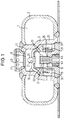
- Figure 1 the only drawing, shows a longitudinal section through an embodiment of the invention, as a hybrid gas generator trained gas generator.
- FIG 1 is a hybrid annulus gas generator for a Vehicle occupant restraint system, more specifically for inflating one Driver gas bags shown.
- the housing of the gas generator has one outer wall 3 and an inner spaced radially from it Wall 5 on. Between the walls is an annular one Pressure chamber 7 is formed, which is filled with compressed gas.
- the inner one Wall 5 separates the pressure chamber 7 from a radially inner space is divided into individual chambers.
- An upper one Outflow opening 9 adjacent mixing chamber 11 is through a Intermediate floor 13 separated from two lower chambers, namely one radially inner expansion chamber 15 into which an igniter 17 projects, and a radially outer annular combustion chamber 19.
- the combustion chamber 19 is filled with fuel in the form of tablets.
- detonator diffuser 21 The combustion chamber 19 and the expansion chamber 15 are through a cap-like diffuser, hereinafter referred to as detonator diffuser 21, separated from one another. Since none the chambers inside the housing are completely closed, there is the same pressure in each chamber.
- Several openings 23 in Igniter diffuser 21, openings 25 in the inner wall 5, one central axial opening 27 in the intermediate floor and two diametrically opposite, upper openings 29 serve in the inner wall 5 the pressure equalization and of course to the fact that the gas generated in Restraint case specifically reaches the outlet opening 9.
- the igniter 17 is gas and pressure tight on a closure part 31 in Forms a disk-shaped base plate attached and forms with this is a pre-assembled unit.
- the gas and pressure tight connection is achieved in that a detonator cap 33 made of metal, which the Surrounds primary and secondary charge of the igniter, preferably by Laser welding is attached to the closure part in a gastight and pressure-tight manner. A corresponding weld seam is marked with 35.
- the ignition material the secondary charge surrounding the primary charge immediately borders to the detonator cap 33.
- the detonator cap is cylindrical formed and has an end wall projecting into the expansion chamber 15 as well as a cylindrical jacket.
- the closure part 31 has on the inside i.e.
- the closure part 31 also has one outside recess 41, protrude into the plug contacts 43 of the igniter. However, the plug contacts 43 do not protrude from the closure part 31 to the outside, so that they do not when transporting the gas generator can be bent.
- the closure part 31 is used for gas-tight and pressure-tight closing of a filling opening 37 Filling opening 37 is filled with fuel in the combustion chamber 19. Then the closure part 31 is placed on the filling opening 37 set and welded to the housing. Eventually, a opposite filling opening for gas, which is already shown in FIG a closure in the form of a diffuser 41 with attached Rupture disc 43 is shown closed, filled with compressed gas Diffuser 41 attached and also welded to the housing.
- a trigger sensor activates the Igniter 17 so that the primary and secondary charge burn off and gas as well as generate hot particles.
- the detonator cap 33 is designed that its end wall, which faces the rupture disk 43, first opens and accompanies the gases and particles at high speed from a pressure wave, enter the expansion chamber 15 and itself distribute it evenly. Part of the pressure wave, the hot gases and particle hits directly through opening 27 on the rupture disc 43 and leads to their immediate destruction. The other part of the hot gases and particles gets through the Openings 23 in the combustion chamber 19, where they are used to ignite the fuel to lead. The gases generated when the fuel burns in turn flow through the openings 25 into the pressure chamber and mix with the compressed gas. The hot gas mixes with the cold compressed gas and burns afterwards.
Landscapes
- Physics & Mathematics (AREA)
- Fluid Mechanics (AREA)
- Engineering & Computer Science (AREA)
- Mechanical Engineering (AREA)
- Air Bags (AREA)
Applications Claiming Priority (2)
| Application Number | Priority Date | Filing Date | Title |
|---|---|---|---|
| DE19723256 | 1997-06-03 | ||
| DE19723256A DE19723256A1 (de) | 1997-06-03 | 1997-06-03 | Gasgenerator |
Publications (1)
| Publication Number | Publication Date |
|---|---|
| EP0882629A1 true EP0882629A1 (fr) | 1998-12-09 |
Family
ID=7831269
Family Applications (1)
| Application Number | Title | Priority Date | Filing Date |
|---|---|---|---|
| EP98110065A Withdrawn EP0882629A1 (fr) | 1997-06-03 | 1998-06-03 | Générateur de gaz |
Country Status (3)
| Country | Link |
|---|---|
| US (1) | US5957492A (fr) |
| EP (1) | EP0882629A1 (fr) |
| DE (1) | DE19723256A1 (fr) |
Cited By (1)
| Publication number | Priority date | Publication date | Assignee | Title |
|---|---|---|---|---|
| EP2471692B2 (fr) † | 2009-05-11 | 2022-01-05 | Joyson Safety Systems Germany GmbH | Générateur de gaz pour gonfler un coussin de sécurité gonflable d'un dispositif de retenue d'occupants d'un véhicule et procédé de gonflage d'un coussin de sécurité gonflable |
Families Citing this family (6)
| Publication number | Priority date | Publication date | Assignee | Title |
|---|---|---|---|---|
| DE19723260A1 (de) * | 1997-06-03 | 1998-12-10 | Temic Bayern Chem Airbag Gmbh | Gasgenerator |
| DE19723259A1 (de) * | 1997-06-03 | 1998-12-10 | Temic Bayern Chem Airbag Gmbh | Gasgenerator sowie Verfahren zum Betreiben eines Gasgenerators |
| DE20020103U1 (de) | 2000-11-27 | 2001-04-05 | TRW Airbag Systems GmbH & Co. KG, 84544 Aschau | Pyrotechnischer Gasgenerator |
| US6918340B2 (en) | 2002-09-12 | 2005-07-19 | Textron Systems Corporation | Dual-stage gas generator utilizing eco-friendly gas generant formulation for military applications |
| US6877435B2 (en) | 2002-09-12 | 2005-04-12 | Textron Systems Corporation | Dual-stage gas generator utilizing eco-friendly gas generant formulation |
| DE202004016556U1 (de) * | 2004-10-26 | 2005-03-17 | Trw Airbag Sys Gmbh | Gasgenerator |
Citations (6)
| Publication number | Priority date | Publication date | Assignee | Title |
|---|---|---|---|---|
| DE19533606A1 (de) | 1994-09-13 | 1996-03-14 | Trw Inc | Airbag-Aufblasvorrichtung mit Drucksensor |
| EP0741064A2 (fr) * | 1995-05-02 | 1996-11-06 | Oea, Inc. | Procédé de fabrication d'un générateur hybride de gaz stocké dans un boîtier toroidal |
| US5609361A (en) * | 1995-08-24 | 1997-03-11 | Trw Vehicle Safety Systems Inc. | Inflation fluid container and initiator with press-fit fluid seal |
| US5630619A (en) * | 1996-02-28 | 1997-05-20 | Morton International, Inc. | Hybrid adaptive inflator for airbags |
| DE19601448A1 (de) * | 1996-01-17 | 1997-07-24 | Temic Bayern Chem Airbag Gmbh | Verschluß für einen Gasgenerator |
| WO1998009851A1 (fr) * | 1996-09-09 | 1998-03-12 | Atlantic Research Corporation | Gonfleur hybride cote conducteur a volume variable |
Family Cites Families (7)
| Publication number | Priority date | Publication date | Assignee | Title |
|---|---|---|---|---|
| JPS4716498Y1 (fr) * | 1970-04-25 | 1972-06-09 | ||
| DE2362513A1 (de) * | 1972-12-18 | 1974-07-04 | Aerojet General Co | Vorrichtung und verfahren zur erzeugung und zum ausblasen von gas |
| DE7422465U (de) * | 1973-07-05 | 1978-03-09 | Allied Chemical Corp., Morristown, N.J. (V.St.A.) | Vorrichtung zum Aufblasen einer Kraftfahrzeugsicherheitseinrichtung |
| US5100174A (en) * | 1990-12-18 | 1992-03-31 | Trw, Inc. | Auto ignition package for an air bag inflator |
| US5184846A (en) * | 1991-11-01 | 1993-02-09 | Trw Vehicle Safety Systems Inc. | Inflator assembly |
| KR0148835B1 (ko) * | 1993-08-20 | 1998-10-15 | 제임스 엠. 루즈벨트 | 팽창 기구를 팽창시키는 장치 |
| US5762368A (en) * | 1996-06-20 | 1998-06-09 | Trw Vehicle Safety Systems Inc. | Initiator for air bag inflator |
-
1997
- 1997-06-03 DE DE19723256A patent/DE19723256A1/de not_active Withdrawn
-
1998
- 1998-06-03 EP EP98110065A patent/EP0882629A1/fr not_active Withdrawn
- 1998-06-03 US US09/089,655 patent/US5957492A/en not_active Expired - Fee Related
Patent Citations (6)
| Publication number | Priority date | Publication date | Assignee | Title |
|---|---|---|---|---|
| DE19533606A1 (de) | 1994-09-13 | 1996-03-14 | Trw Inc | Airbag-Aufblasvorrichtung mit Drucksensor |
| EP0741064A2 (fr) * | 1995-05-02 | 1996-11-06 | Oea, Inc. | Procédé de fabrication d'un générateur hybride de gaz stocké dans un boîtier toroidal |
| US5609361A (en) * | 1995-08-24 | 1997-03-11 | Trw Vehicle Safety Systems Inc. | Inflation fluid container and initiator with press-fit fluid seal |
| DE19601448A1 (de) * | 1996-01-17 | 1997-07-24 | Temic Bayern Chem Airbag Gmbh | Verschluß für einen Gasgenerator |
| US5630619A (en) * | 1996-02-28 | 1997-05-20 | Morton International, Inc. | Hybrid adaptive inflator for airbags |
| WO1998009851A1 (fr) * | 1996-09-09 | 1998-03-12 | Atlantic Research Corporation | Gonfleur hybride cote conducteur a volume variable |
Cited By (1)
| Publication number | Priority date | Publication date | Assignee | Title |
|---|---|---|---|---|
| EP2471692B2 (fr) † | 2009-05-11 | 2022-01-05 | Joyson Safety Systems Germany GmbH | Générateur de gaz pour gonfler un coussin de sécurité gonflable d'un dispositif de retenue d'occupants d'un véhicule et procédé de gonflage d'un coussin de sécurité gonflable |
Also Published As
| Publication number | Publication date |
|---|---|
| US5957492A (en) | 1999-09-28 |
| DE19723256A1 (de) | 1998-12-10 |
Similar Documents
| Publication | Publication Date | Title |
|---|---|---|
| DE69308808T2 (de) | Hybrider Gasgenerator für aufblasbare Luftsack-Rückhaltesysteme | |
| DE69620114T2 (de) | Unabhängiger,pyrotechnischer Zünder für eine Aufblasvorrichtung | |
| DE19654315A1 (de) | Hybrid-Gasgenerator | |
| DE69504331T2 (de) | Hybride aufblasvorrichtung | |
| DE19728438A1 (de) | Pyrotechnischer Gasgenerator | |
| EP0844949A1 (fr) | Dispositif de remplissage d'un element de retenue | |
| DE69424955T2 (de) | Aufblasanordnung | |
| DE112017005654T5 (de) | Gaserzeuger | |
| EP0882629A1 (fr) | Générateur de gaz | |
| EP0882628B1 (fr) | Générateur de gaz | |
| DE112017001991T5 (de) | Gas-Generator | |
| DE19725476A1 (de) | Gasgenerator | |
| EP0882627B1 (fr) | Générateur de gaz et méthode de fonctionnement d'un générateur de gaz | |
| DE19541924A1 (de) | Gasgenerator | |
| DE4138988A1 (de) | Gasgenerator, insbesondere rohrgasgenerator fuer ein aufblasbares aufprallschutzkissen | |
| EP1702815A2 (fr) | Générateur de gaz froid | |
| DE19701663B4 (de) | Gasgenerator | |
| DE19635637A1 (de) | Hybrid-Gasgenerator | |
| DE19529553A1 (de) | Anordnung zum Öffnen der Berstmembran von Druckgasflaschen in Gasgeneratoren | |
| DE19725475A1 (de) | Gasgenerator | |
| DE19631314B4 (de) | Hybrid-Gasgenerator | |
| DE19723257A1 (de) | Hybrid-Gasgenerator | |
| DE19631315A1 (de) | Hybrid-Gasgenerator | |
| DE102018119084A1 (de) | Deflektorbauteil, Gasgenerator, Gassackmodul, Fahrzeugsicherheitssystem und Verfahren zum Betreiben eines Gasgenerators | |
| DE19631316B4 (de) | Hybrid-Gasgenerator |
Legal Events
| Date | Code | Title | Description |
|---|---|---|---|
| PUAI | Public reference made under article 153(3) epc to a published international application that has entered the european phase |
Free format text: ORIGINAL CODE: 0009012 |
|
| AK | Designated contracting states |
Kind code of ref document: A1 Designated state(s): DE FR IT NL |
|
| AX | Request for extension of the european patent |
Free format text: AL;LT;LV;MK;RO;SI |
|
| 17P | Request for examination filed |
Effective date: 19990609 |
|
| AKX | Designation fees paid |
Free format text: DE FR IT NL |
|
| 17Q | First examination report despatched |
Effective date: 20001016 |
|
| STAA | Information on the status of an ep patent application or granted ep patent |
Free format text: STATUS: THE APPLICATION IS DEEMED TO BE WITHDRAWN |
|
| 18D | Application deemed to be withdrawn |
Effective date: 20010427 |