EP0882641A2 - Fahrerhausfederung eines landwirtschaftliches Fahrzeugs - Google Patents
Fahrerhausfederung eines landwirtschaftliches Fahrzeugs Download PDFInfo
- Publication number
- EP0882641A2 EP0882641A2 EP98201813A EP98201813A EP0882641A2 EP 0882641 A2 EP0882641 A2 EP 0882641A2 EP 98201813 A EP98201813 A EP 98201813A EP 98201813 A EP98201813 A EP 98201813A EP 0882641 A2 EP0882641 A2 EP 0882641A2
- Authority
- EP
- European Patent Office
- Prior art keywords
- cab
- chassis
- agricultural vehicle
- vehicle according
- aft end
- Prior art date
- Legal status (The legal status is an assumption and is not a legal conclusion. Google has not performed a legal analysis and makes no representation as to the accuracy of the status listed.)
- Granted
Links
- 239000000725 suspension Substances 0.000 title description 9
- 230000008878 coupling Effects 0.000 claims description 12
- 238000010168 coupling process Methods 0.000 claims description 12
- 238000005859 coupling reaction Methods 0.000 claims description 12
- 230000010355 oscillation Effects 0.000 claims description 6
- 230000035939 shock Effects 0.000 claims description 4
- 241001247986 Calotropis procera Species 0.000 claims description 3
- 239000006096 absorbing agent Substances 0.000 claims description 2
- 239000011295 pitch Substances 0.000 description 7
- 230000007246 mechanism Effects 0.000 description 3
- 238000013016 damping Methods 0.000 description 2
- 238000012423 maintenance Methods 0.000 description 2
- 239000003381 stabilizer Substances 0.000 description 2
- 230000005540 biological transmission Effects 0.000 description 1
- 238000010276 construction Methods 0.000 description 1
- 230000005484 gravity Effects 0.000 description 1
- 238000002955 isolation Methods 0.000 description 1
- QSHDDOUJBYECFT-UHFFFAOYSA-N mercury Chemical compound [Hg] QSHDDOUJBYECFT-UHFFFAOYSA-N 0.000 description 1
- 229910052753 mercury Inorganic materials 0.000 description 1
- 230000007935 neutral effect Effects 0.000 description 1
- 238000004904 shortening Methods 0.000 description 1
Images
Classifications
-
- B—PERFORMING OPERATIONS; TRANSPORTING
- B62—LAND VEHICLES FOR TRAVELLING OTHERWISE THAN ON RAILS
- B62D—MOTOR VEHICLES; TRAILERS
- B62D33/00—Superstructures for load-carrying vehicles
- B62D33/06—Drivers' cabs
- B62D33/0604—Cabs insulated against vibrations or noise, e.g. with elastic suspension
-
- B—PERFORMING OPERATIONS; TRANSPORTING
- B60—VEHICLES IN GENERAL
- B60G—VEHICLE SUSPENSION ARRANGEMENTS
- B60G99/00—Subject matter not provided for in other groups of this subclass
- B60G99/002—Suspension details of the suspension of the vehicle body on the vehicle chassis
-
- B—PERFORMING OPERATIONS; TRANSPORTING
- B60—VEHICLES IN GENERAL
- B60G—VEHICLE SUSPENSION ARRANGEMENTS
- B60G2200/00—Indexing codes relating to suspension types
- B60G2200/30—Rigid axle suspensions
- B60G2200/34—Stabilising mechanisms, e.g. for lateral stability
- B60G2200/342—Watt linkage
-
- B—PERFORMING OPERATIONS; TRANSPORTING
- B60—VEHICLES IN GENERAL
- B60G—VEHICLE SUSPENSION ARRANGEMENTS
- B60G2204/00—Indexing codes related to suspensions per se or to auxiliary parts
- B60G2204/10—Mounting of suspension elements
- B60G2204/16—Mounting of vehicle body on chassis
- B60G2204/162—Cabins, e.g. for trucks, tractors
Definitions
- the present invention relates to an agricultural vehicle having a cab resiliently supported on the chassis of the vehicle.
- agricultural vehicles such as tractors
- a chassis rigidly connected to the vehicle wheels. Because it is unsprung, the vehicle chassis follows the contour of the ground. It is common for the cab, or operator station, to be mounted directly on the chassis and to rely only on springing in the operator's seat to improve operator comfort. This however is not entirely satisfactory and it has therefore been proposed to support the cab on rubber mounts that provide an improved degree of cushioning.
- a further suspension system enables the cab to be resiliently mounted on the vehicle chassis.
- stabiliser linkages are provided on the tractor fore and aft of the cab to limit the movement of the pivotal connection of the stabiliser linkages to the cab to essentially a vertical movement which lies in a vertical plane including the longitudinal centres of the vehicle chassis and the cab.
- a complex sway or yaw limiting mechanism as well as a pitch limiting mechanism are provided to limit the pitch and roll of the cab as it moves through the vertical plane relative to the vehicle chassis.
- an agricultural vehicle having a chassis and a cab mounted on the chassis, wherein the fore end of the cab is mounted on the chassis for pivotal movement about a transverse axis but is prevented from moving relative to the chassis in a vertical plane, and the aft end of the cab is resiliently supported on the chassis and is connected to the chassis by means of a linkage that permits movement of the aft end of the cab in a vertical direction towards and away from the chassis while preventing transverse movement of the aft end of the cab.
- the suspension of the present invention fixes the fore end and only allows movement of the aft end of the cab.
- the cab in the present invention can pivot at its fore end about a transverse axis but cannot, as a whole, move vertically on the chassis without pitching.
- the invention recognises that the operator seat is located well back in the cab and it is at the back of the cab that movement is required to provide operator comfort.
- the fore end of the cab on the other band contains the steering and other control mechanisms and allowing vertical movement of the cab at its fore end merely introduces complexity without offering any particular advantage from the point of view of shock isolation.
- the movement of the aft end of the cab in relation to the chassis may be constrained to the vertical direction by the use of any suitable form of linkage.
- a roller may be fixed on the cab to follow a linear track fixed to the chassis.
- a Watts linkage is used to connect the aft end of the cab to the chassis.
- the Watts linkage preferably comprises a relatively short double arm lever rotatably mounted on the chassis and two relatively long levers extending in opposite directions from the ends of the double arm lever to pivot points fixed to opposite sides of the cab.
- the mounting at the fore end of the cab is a gimbal mounting that allows the cab to roll and pitch relative to the chassis and to provide a generally transversely extending rod (herein termed a Panhard rod) connected at its one end to the chassis and at its other end to a point on the cab.
- a Panhard rod is of variable length, then by shortening and lengthening the effective length of the rod, the cab can intentionally be made to roll relative to the chassis.
- a level sensing means is provided in the cab, then its output signal can be used to set the length of the Panhard rod so that the cab may remain plumb vertical when one wheel of the vehicle is in a furrow or when driving along a banked surface.
- the effective length of the Panhard rod may in this case be varied by rotating a lever or an eccentric connecting one end of the rod to the chassis or to the cab.
- the aft end of the cab may be resiliently supported on the chassis by means of two springs located under the aft end of the cab. Damping of oscillations can be effected by means of hydraulic shock absorbers within the springs or by means of rubber bushes built into the various pivots of the Watts linkage.
- Panhard rod It is also possible to incorporate a spring and damper into the Panhard rod to allow some degree of damped roll as the vehicle is being driven.
- the present invention also provides, in accordance with a second aspect, an agricultural vehicle having a chassis, lifting equipment for attaching auxiliary devices to the vehicle, and a cab mounted on the chassis, wherein one end of the cab is mounted on the chassis for pivotal movement about a transverse axis but is prevented from moving relative to the chassis in a vertical plane and the other end of the cab is releasably supported on the chassis, wherein coupling means are provided on the said other end of the cab for connection to the lifting equipment of the vehicle, to permit the cab to be pivoted about its said one end relative to the chassis by the action of the lifting equipment.
- the provision of a fixed pivot at one end of the cab, preferably its fore end, allows the cab to be tilted away from the chassis to provide access for servicing and maintenance.
- the second aspect of the invention allows advantage to be taken of such a cab suspension geometry and the existence of lifting equipment on the vehicle, to simplify the task of gaining access to components of the chassis lying beneath the cab.
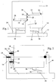
- Figures 1 and 2 show part of a tractor, namely the cab 10 and part of the chassis 12.
- the term chassis refers to the entire unsprung mass of the tractor which in addition to the rear wheel axle commonly includes the engine and the transmission.
- the cab 10 is suspended from posts 16 and 44 that extend upwards from the chassis 12.
- the cab 10 is mounted on the post 44 that lies at its fore end by means of a coupling 46, represented by a ball, that allows the cab to pivot in all directions about the centre of the coupling.
- the coupling 46 is however fixed on the cab 10 and on the post 44 and prevents the fore end of the cab 10 from moving vertically or transversely relative to the post 44.
- the cab 10 At its aft end, the cab 10 is supported on the chassis 12 by means of springs 14. The cab 10 is also connected to the post 16 arranged at its aft end by means of a Watts linkage, shown in Figure 1.
- the Watts linkage which has been exposed by cutting away a part of the post 16 and is described in greater detail below, allows the aft end of the cab 10 to move up and down relative to the chassis 12 while preventing it from moving from side to side. In other words, the linkage allows pitching of the cab 10 relative to the chassis 10 but prevents yaw.
- the Watts linkage comprises a short lever 20 that is pivotably mounted at its centre on the post 16 by means of a pivot pin 18.
- the lever 20 is substantially vertical when the vehicle is at rest on a level surface.
- Each of the free ends of the lever 20 is pivotably connected by respective pivot pins 30 and 32 to two long levers 22 and 24.
- the other ends of the long levers 22 and 24 are pivotably connected to opposite sides of the cab 10 by respective pivot pins 26 and 28.
- Some or all of the various pivots of the Watts linkage incorporate rubber bushes, designated 40 and 42 in Figure 2, to damp the oscillation of the cab 10 on the chassis 12.
- the coupling 46 and the central pivot pin 18 of the short lever 20 of the Watts linkage lie on a line with each other so that the cab 10 can roll about this fore/aft axis, which preferably passes through the centre of gravity of the cab 10.
- Such roll movement is prevented by means of a Panhard rod 34 that is connected by suitable pivot joints 36 and 38 to the chassis 12 and the cab 10 respectively.
- the cab can remain substantially stationary in relation to the ground while the wheels of the chassis follow the contours of the ground.
- the vertical movement of the cab is accompanied by a slight amount of roll which depends on the relative lengths of the short and long levers which in practice can be minimal. If the Panhard rod 34 incorporates a spring and a damper then it will allow damped roll movement of the cab 10 and the chassis 12.
- any alternative means may be used to constrain the aft end of the cab 10 to move only in a vertical direction and withstand lateral forces.
- the aft end only of the cab 10 will move vertically while supported on the springs 14 and prevent shocks from being transmitted to the operator's seat that is located towards the rear of the cab 10.
- the fore end of the cab 10 will however move vertically with the chassis as the cab pitches about the coupling 46.
- the cab 10 always remains perpendicular to the road wheel axle but this is not always desirable. For example, when the vehicle is working on a banked surface, or has one wheel in a furrow, it is preferred for the cab to remain plumb vertical.
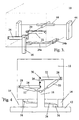
- the rod in this case comprises a first long lever 34a and a second shorter lever 34b (which may alternatively be an eccentric) that is rotatably mounted on the cab 10, as shown in Figure 3, or alternatively on the chassis. If the lever 34b is rotated clockwise as viewed from above in Figure 3, the effective length of the Panhard rod is increased and this causes the cab 10 to rotate about the roll axis in an anticlockwise direction as viewed from the aft end of the cab 10.
- the cab incorporates a level sensor (not shown), which may for example be a mercury switch, the output of which is used by a suitable control system to set the position lever 34b to ensure automatic selflevelling of the cab 10.
- This embodiment also shows an alternative construction of the coupling 46, which in this case is formed as a gimbal mount.
- a transverse rod pivotably mounted in two posts 44 arranged at the fore end of the cab 10 is connected to the cab at its centre by a longitudinally extending pivot pin.
- the cab 10 can roll about the longitudinal pivot and pitch by rotation of the transverse rod in the vertical posts 44.
- the front coupling 46 therefore allows pivoting about only two axes and it assists the linkage at the aft end of the cab 10 in resisting yaw.
- FIG. 4 shows and alternative means of damping oscillations of the cab 10. While it is possible to rely on dampers incorporated in the pivots of the Watts linkage and in the spring 14, a further possibility is to provide gas struts 50 and 52 or hydraulic dampers between the post 16 and the cab 10.
- An advantage of the suspension geometry of the cab in a vehicle of the invention is that the cab can readily be tilted forwards to allow access to components of the chassis for servicing.
- the entire cab can be tilted about its fore end on the coupling 46.
- the post 16 may include two separable parts that allow the pin 18 to be raised off the post 16 after they have been separated from one another.
- the pin 18 may for example be held captive between the top of the post and a clamping block that may be removed from the post 16 or pivoted relative to the post 16 out of the way of the pin 18.
Landscapes
- Engineering & Computer Science (AREA)
- Mechanical Engineering (AREA)
- Chemical & Material Sciences (AREA)
- Combustion & Propulsion (AREA)
- Transportation (AREA)
- Body Structure For Vehicles (AREA)
- Vehicle Body Suspensions (AREA)
Applications Claiming Priority (2)
| Application Number | Priority Date | Filing Date | Title |
|---|---|---|---|
| GB9711687 | 1997-06-06 | ||
| GB9711687A GB2326137A (en) | 1997-06-06 | 1997-06-06 | Cab suspension for an agricultural vehicle |
Publications (3)
| Publication Number | Publication Date |
|---|---|
| EP0882641A2 true EP0882641A2 (de) | 1998-12-09 |
| EP0882641A3 EP0882641A3 (de) | 1999-06-16 |
| EP0882641B1 EP0882641B1 (de) | 2003-06-11 |
Family
ID=10813650
Family Applications (1)
| Application Number | Title | Priority Date | Filing Date |
|---|---|---|---|
| EP98201813A Expired - Lifetime EP0882641B1 (de) | 1997-06-06 | 1998-06-02 | Landwirtschaftliches Fahrzeug mit Fahrerhaus und Federung dafür |
Country Status (4)
| Country | Link |
|---|---|
| US (1) | US6206422B1 (de) |
| EP (1) | EP0882641B1 (de) |
| DE (1) | DE69815439T2 (de) |
| GB (1) | GB2326137A (de) |
Cited By (2)
| Publication number | Priority date | Publication date | Assignee | Title |
|---|---|---|---|---|
| EP1764242A1 (de) * | 2005-09-14 | 2007-03-21 | ZF FRIEDRICHSHAFEN Aktiengesellschaft | Aufhängungseinrichtung mit Wattgestänge |
| WO2010136028A1 (de) * | 2009-05-27 | 2010-12-02 | Zf Friedrichshafen Ag | Wattgestänge-aufhängungseinrichtung mit integrierter federung/dämpfung |
Families Citing this family (15)
| Publication number | Priority date | Publication date | Assignee | Title |
|---|---|---|---|---|
| US7712556B2 (en) * | 2000-07-31 | 2010-05-11 | Hammonds Technical Services, Inc. | Omni direction vehicle |
| DE60126091T2 (de) * | 2000-07-31 | 2007-08-30 | Carl L. Humble Hammonds | Allrichtungsfahrzeug |
| US6875103B2 (en) * | 2002-01-07 | 2005-04-05 | Cnh America Llc | Apparatus and method for installing and removing a harvesting combine rotor |
| US6758294B2 (en) | 2002-06-10 | 2004-07-06 | Volvo Trucks North America, Inc. | Laterally damped panhard rod cab suspension |
| US7950726B2 (en) * | 2007-08-17 | 2011-05-31 | Brown Keith R | Air ride system for a tractor cab |
| TWI371334B (en) * | 2009-05-05 | 2012-09-01 | Univ Chung Yuan Christian | Toggle type with one axial positioning machine |
| US8807633B2 (en) | 2011-06-21 | 2014-08-19 | Cnh Industrial America Llc | Cab suspension system for an off-road vehicle |
| DE102013209138A1 (de) * | 2013-05-16 | 2014-11-20 | Deere & Company | Aufhängungseinrichtung |
| CN106005065A (zh) * | 2016-05-30 | 2016-10-12 | 别宜春 | 一种可调整高度的气囊式鹅颈部 |
| US10668954B2 (en) * | 2017-11-30 | 2020-06-02 | John Payne | Cab and hood suspension with hood tilt |
| US10745065B2 (en) * | 2018-04-16 | 2020-08-18 | Howe & Howe Inc. | Vehicle with pneumatically suspended operator compartment |
| DE102018112019B4 (de) * | 2018-05-18 | 2022-10-06 | Grammer Aktiengesellschaft | Fahrzeugsitz mit einer Dämpfungseinrichtung |
| US11639202B2 (en) | 2020-10-30 | 2023-05-02 | Volvo Truck Corporation | Truck or tractor vehicle with adjustable panhard bar and method for adjusting alignment of a truck or tractor vehicle cab relative to a truck or tractor vehicle frame |
| CN114228845A (zh) * | 2021-11-30 | 2022-03-25 | 江苏徐工工程机械研究院有限公司 | 一种悬置装置及其控制方法、车辆和工程机械 |
| US20250263133A1 (en) * | 2024-02-19 | 2025-08-21 | CNH Industrial Brasil Ltda. | System and method for work vehicle |
Citations (1)
| Publication number | Priority date | Publication date | Assignee | Title |
|---|---|---|---|---|
| US4043584A (en) | 1975-11-17 | 1977-08-23 | Allis-Chalmers Corporation | Vehicle suspension and stabilizer system |
Family Cites Families (22)
| Publication number | Priority date | Publication date | Assignee | Title |
|---|---|---|---|---|
| DE1911118B2 (de) * | 1969-03-05 | 1973-09-27 | Daimler-Benz Ag, 7000 Stuttgart | Vorrichtung zum Kippen des Fahrerhauses von Nutzkraftwagen |
| NL7207207A (de) * | 1971-12-09 | 1973-06-13 | ||
| US3944017A (en) * | 1974-12-23 | 1976-03-16 | Ford Motor Company | Suspension for truck cab |
| US4487286A (en) * | 1975-01-30 | 1984-12-11 | Lely Cornelis V D | Tractor |
| FR2456263A1 (fr) * | 1979-05-09 | 1980-12-05 | Unic Sa | Dispositif de suspension, notamment d'une cabine, sur le chassis d'un vehicule |
| DE3000606A1 (de) * | 1980-01-09 | 1981-07-16 | Fritzmeier AG, Oberentfelden | Nutzfahrzeug mit abgefederten kabine |
| DE3172007D1 (en) * | 1981-05-22 | 1985-10-03 | Deere & Co | Cabin for a motor vehicle, especially for a combine |
| GB2129379B (en) * | 1982-08-19 | 1986-07-09 | Sanwa Seiki Mfg Co Ltd | Vehicle cab tilting system |
| US4483409A (en) * | 1983-03-07 | 1984-11-20 | Applied Power Inc. | Integral hydraulic tilt-cab suspension and tilting apparatus |
| US4558881A (en) * | 1983-10-11 | 1985-12-17 | Ingersoll Equipment Co., Inc. | Tractor-mounted implement hitch arrangement |
| GB2190336B (en) * | 1985-11-30 | 1989-10-18 | Gkn Sankey Ltd | Improvements in off-the-road vehicles |
| US4805322A (en) * | 1987-01-30 | 1989-02-21 | Lemire Antoine Noel | Excavating blade assembly |
| US4776606A (en) * | 1987-11-20 | 1988-10-11 | Deere & Company | Hitch and drive structure for pto-driven, semi-integral implement |
| US4817730A (en) * | 1988-02-16 | 1989-04-04 | Deere & Company | Hydraulic weight transfer system for an implement with a lift assist wheel |
| US5044455A (en) * | 1990-02-16 | 1991-09-03 | Navistar International Transportion Corp. | Actively controlled truck cab suspension |
| US5209316A (en) * | 1991-10-16 | 1993-05-11 | Applied Power Inc. | Truck cab suspension unit |
| DE9312640U1 (de) * | 1992-08-31 | 1994-01-13 | Deere & Company, Niederlassung Deere & Co. European Office, Mannheim, Moline, Ill. | Fahrerplattformaufhängung für Fahrzeuge |
| DE4235797C2 (de) * | 1992-10-23 | 1994-12-08 | Deere & Co | Kraftfahrzeug mit Hubgerüst |
| US5346018A (en) * | 1992-10-26 | 1994-09-13 | Koster Rick L | Vehicle hydraulic three-point hitch and power take-off shaft |
| US5458359A (en) * | 1994-08-08 | 1995-10-17 | Brandt; Larry A. | Missing link swivel for four-link rigid axle suspensions |
| US5577571A (en) * | 1996-02-12 | 1996-11-26 | Rizzoli; Robert L. | Automobile chassis with pivoted inner and outer frames |
| FR2749265B1 (fr) * | 1996-06-03 | 1998-09-04 | Michel Ets | Vehicule a partie de caisse, notamment a cabine de conduite, suspendue elastiquement |
-
1997
- 1997-06-06 GB GB9711687A patent/GB2326137A/en not_active Withdrawn
-
1998
- 1998-06-02 DE DE69815439T patent/DE69815439T2/de not_active Expired - Fee Related
- 1998-06-02 EP EP98201813A patent/EP0882641B1/de not_active Expired - Lifetime
- 1998-06-05 US US09/092,440 patent/US6206422B1/en not_active Expired - Lifetime
Patent Citations (1)
| Publication number | Priority date | Publication date | Assignee | Title |
|---|---|---|---|---|
| US4043584A (en) | 1975-11-17 | 1977-08-23 | Allis-Chalmers Corporation | Vehicle suspension and stabilizer system |
Cited By (7)
| Publication number | Priority date | Publication date | Assignee | Title |
|---|---|---|---|---|
| EP1764242A1 (de) * | 2005-09-14 | 2007-03-21 | ZF FRIEDRICHSHAFEN Aktiengesellschaft | Aufhängungseinrichtung mit Wattgestänge |
| EP1905620A1 (de) * | 2005-09-14 | 2008-04-02 | Zf Friedrichshafen Ag | Aufhängungseinrichtung mit Wattgestänge |
| WO2010136028A1 (de) * | 2009-05-27 | 2010-12-02 | Zf Friedrichshafen Ag | Wattgestänge-aufhängungseinrichtung mit integrierter federung/dämpfung |
| CN102341297A (zh) * | 2009-05-27 | 2012-02-01 | Zf腓特烈斯哈芬股份公司 | 具有集成的弹簧装置/减振装置的瓦特连杆悬架装置 |
| US8348334B2 (en) | 2009-05-27 | 2013-01-08 | Zf Friedrichshafen Ag | Watt linkage suspension device having integrated compliance and damping |
| CN102341297B (zh) * | 2009-05-27 | 2014-01-08 | Zf腓特烈斯哈芬股份公司 | 具有集成的弹簧装置/减振装置的瓦特连杆悬架装置 |
| RU2526542C2 (ru) * | 2009-05-27 | 2014-08-27 | Цф Фридрихсхафен Аг | Устройство подвески с рычажным механизмом уатта с интегрированным подрессориванием/демпфированием |
Also Published As
| Publication number | Publication date |
|---|---|
| GB9711687D0 (en) | 1997-08-06 |
| US6206422B1 (en) | 2001-03-27 |
| EP0882641B1 (de) | 2003-06-11 |
| DE69815439D1 (de) | 2003-07-17 |
| EP0882641A3 (de) | 1999-06-16 |
| GB2326137A (en) | 1998-12-16 |
| DE69815439T2 (de) | 2003-12-18 |
Similar Documents
| Publication | Publication Date | Title |
|---|---|---|
| EP0882641B1 (de) | Landwirtschaftliches Fahrzeug mit Fahrerhaus und Federung dafür | |
| CA1163567A (en) | Rear-wheel suspension device for a tricycle vehicle | |
| US4275918A (en) | Resilient suspension for the cab of an agricultural tractor | |
| EP1222082B1 (de) | Einzelradaufhängung | |
| EP0825040A2 (de) | Aufhängung mit unabhängiger Lenkung mit hoher Nachgiebigkeit in Längsrichtung und hoher Nachlauf-Winkelstabilität | |
| US5197755A (en) | Independent wheel suspension system for vehicles | |
| US4161322A (en) | Vehicles having reduced tilting of the superstructure thereof relative to the wheel axle support therefor | |
| NO177342B (no) | Kjöreverk for lavgulv-skinnekjöretöy | |
| KR20100016064A (ko) | 롤-안정화 제 5 휠 장치 | |
| CA2403731A1 (en) | Commercial vehicule having an elastically suspended driver's cab | |
| JP2003146041A (ja) | 側方−揺動制御リンク装置を持つ被懸架アクスル | |
| GB2310838A (en) | Vehicle axle assembly | |
| US20020157891A1 (en) | Bogey beam axle support for utility vehicles | |
| US4418932A (en) | Front axle suspension system for a vehicle chassis | |
| US4053170A (en) | Panhard spring suspension arrangement for off-road vehicles | |
| US4614358A (en) | Stabilizer for vehicles | |
| CA1062736A (en) | Vehicle suspension and stabilizer system | |
| CA2286682C (en) | Front axle suspension | |
| US5333895A (en) | Dual rear axle system for large vehicles | |
| US7334806B2 (en) | Torque reaction control link | |
| US5240278A (en) | Vehicle suspension | |
| EP1298042B1 (de) | Aufhängevorrichtung für die dritte Achse eines Nutzfahrzeugs | |
| EP0847883B1 (de) | Hinterradaufhängung für ein Kraftfahrzeug | |
| GB2102661A (en) | Support for crop spraying boom | |
| US6766872B2 (en) | Rear axle suspension mechanism for utility vehicles |
Legal Events
| Date | Code | Title | Description |
|---|---|---|---|
| PUAI | Public reference made under article 153(3) epc to a published international application that has entered the european phase |
Free format text: ORIGINAL CODE: 0009012 |
|
| AK | Designated contracting states |
Kind code of ref document: A2 Designated state(s): DE FR GB IT |
|
| AX | Request for extension of the european patent |
Free format text: AL;LT;LV;MK;RO;SI |
|
| PUAL | Search report despatched |
Free format text: ORIGINAL CODE: 0009013 |
|
| AK | Designated contracting states |
Kind code of ref document: A3 Designated state(s): AT BE CH CY DE DK ES FI FR GB GR IE IT LI LU MC NL PT SE |
|
| AX | Request for extension of the european patent |
Free format text: AL;LT;LV;MK;RO;SI |
|
| 17P | Request for examination filed |
Effective date: 19991129 |
|
| AKX | Designation fees paid |
Free format text: DE FR GB IT |
|
| 17Q | First examination report despatched |
Effective date: 20020307 |
|
| GRAH | Despatch of communication of intention to grant a patent |
Free format text: ORIGINAL CODE: EPIDOS IGRA |
|
| RTI1 | Title (correction) |
Free format text: AGRICULTURAL VEHICLE WITH CAB AND CAB SUSPENSION |
|
| RAP1 | Party data changed (applicant data changed or rights of an application transferred) |
Owner name: CNH U.K. LIMITED |
|
| GRAH | Despatch of communication of intention to grant a patent |
Free format text: ORIGINAL CODE: EPIDOS IGRA |
|
| GRAA | (expected) grant |
Free format text: ORIGINAL CODE: 0009210 |
|
| AK | Designated contracting states |
Designated state(s): DE FR GB IT |
|
| REG | Reference to a national code |
Ref country code: GB Ref legal event code: FG4D |
|
| REF | Corresponds to: |
Ref document number: 69815439 Country of ref document: DE Date of ref document: 20030717 Kind code of ref document: P |
|
| ET | Fr: translation filed | ||
| PLBE | No opposition filed within time limit |
Free format text: ORIGINAL CODE: 0009261 |
|
| STAA | Information on the status of an ep patent application or granted ep patent |
Free format text: STATUS: NO OPPOSITION FILED WITHIN TIME LIMIT |
|
| 26N | No opposition filed |
Effective date: 20040312 |
|
| PGFP | Annual fee paid to national office [announced via postgrant information from national office to epo] |
Ref country code: DE Payment date: 20080415 Year of fee payment: 11 |
|
| REG | Reference to a national code |
Ref country code: GB Ref legal event code: 746 Effective date: 20090114 |
|
| PG25 | Lapsed in a contracting state [announced via postgrant information from national office to epo] |
Ref country code: DE Free format text: LAPSE BECAUSE OF NON-PAYMENT OF DUE FEES Effective date: 20100101 |
|
| PGFP | Annual fee paid to national office [announced via postgrant information from national office to epo] |
Ref country code: GB Payment date: 20130405 Year of fee payment: 16 |
|
| PGFP | Annual fee paid to national office [announced via postgrant information from national office to epo] |
Ref country code: IT Payment date: 20130620 Year of fee payment: 16 Ref country code: FR Payment date: 20130430 Year of fee payment: 16 |
|
| GBPC | Gb: european patent ceased through non-payment of renewal fee |
Effective date: 20140602 |
|
| REG | Reference to a national code |
Ref country code: FR Ref legal event code: ST Effective date: 20150227 |
|
| PG25 | Lapsed in a contracting state [announced via postgrant information from national office to epo] |
Ref country code: IT Free format text: LAPSE BECAUSE OF NON-PAYMENT OF DUE FEES Effective date: 20140602 |
|
| PG25 | Lapsed in a contracting state [announced via postgrant information from national office to epo] |
Ref country code: GB Free format text: LAPSE BECAUSE OF NON-PAYMENT OF DUE FEES Effective date: 20140602 Ref country code: FR Free format text: LAPSE BECAUSE OF NON-PAYMENT OF DUE FEES Effective date: 20140630 |