EP0882647A2 - Décolage et atterrissage extrêmement courts d'un avion utilisant une régulation multiaxe du vecteur de poussée - Google Patents
Décolage et atterrissage extrêmement courts d'un avion utilisant une régulation multiaxe du vecteur de poussée Download PDFInfo
- Publication number
- EP0882647A2 EP0882647A2 EP98109745A EP98109745A EP0882647A2 EP 0882647 A2 EP0882647 A2 EP 0882647A2 EP 98109745 A EP98109745 A EP 98109745A EP 98109745 A EP98109745 A EP 98109745A EP 0882647 A2 EP0882647 A2 EP 0882647A2
- Authority
- EP
- European Patent Office
- Prior art keywords
- aircraft
- thrust
- takeoff
- attack
- landing
- Prior art date
- Legal status (The legal status is an assumption and is not a legal conclusion. Google has not performed a legal analysis and makes no representation as to the accuracy of the status listed.)
- Granted
Links
- 238000007790 scraping Methods 0.000 claims abstract description 9
- 238000013459 approach Methods 0.000 claims description 28
- 238000000034 method Methods 0.000 claims description 12
- RZVHIXYEVGDQDX-UHFFFAOYSA-N 9,10-anthraquinone Chemical compound C1=CC=C2C(=O)C3=CC=CC=C3C(=O)C2=C1 RZVHIXYEVGDQDX-UHFFFAOYSA-N 0.000 abstract description 2
- 230000008901 benefit Effects 0.000 description 8
- 241000985905 Candidatus Phytoplasma solani Species 0.000 description 7
- 238000013461 design Methods 0.000 description 7
- 230000005484 gravity Effects 0.000 description 5
- 230000001133 acceleration Effects 0.000 description 3
- 238000013016 damping Methods 0.000 description 3
- 230000000694 effects Effects 0.000 description 3
- 241000272470 Circus Species 0.000 description 2
- 230000035939 shock Effects 0.000 description 2
- 241000272517 Anseriformes Species 0.000 description 1
- 102100027835 Cell death regulator Aven Human genes 0.000 description 1
- 101000698131 Homo sapiens Cell death regulator Aven Proteins 0.000 description 1
- 238000007664 blowing Methods 0.000 description 1
- 239000000969 carrier Substances 0.000 description 1
- 238000010276 construction Methods 0.000 description 1
- 238000005516 engineering process Methods 0.000 description 1
- 239000012530 fluid Substances 0.000 description 1
- 238000011835 investigation Methods 0.000 description 1
- 238000012986 modification Methods 0.000 description 1
- 230000004048 modification Effects 0.000 description 1
- 238000005096 rolling process Methods 0.000 description 1
- 239000003381 stabilizer Substances 0.000 description 1
- 238000009966 trimming Methods 0.000 description 1
- 239000013585 weight reducing agent Substances 0.000 description 1
Images




Classifications
-
- F—MECHANICAL ENGINEERING; LIGHTING; HEATING; WEAPONS; BLASTING
- F02—COMBUSTION ENGINES; HOT-GAS OR COMBUSTION-PRODUCT ENGINE PLANTS
- F02K—JET-PROPULSION PLANTS
- F02K1/00—Plants characterised by the form or arrangement of the jet pipe or nozzle; Jet pipes or nozzles peculiar thereto
- F02K1/002—Plants characterised by the form or arrangement of the jet pipe or nozzle; Jet pipes or nozzles peculiar thereto with means to modify the direction of thrust vector
-
- B—PERFORMING OPERATIONS; TRANSPORTING
- B64—AIRCRAFT; AVIATION; COSMONAUTICS
- B64C—AEROPLANES; HELICOPTERS
- B64C15/00—Attitude, flight direction, or altitude control by jet reaction
- B64C15/02—Attitude, flight direction, or altitude control by jet reaction the jets being propulsion jets
-
- B—PERFORMING OPERATIONS; TRANSPORTING
- B64—AIRCRAFT; AVIATION; COSMONAUTICS
- B64C—AEROPLANES; HELICOPTERS
- B64C25/00—Alighting gear
- B64C25/001—Devices not provided for in the groups B64C25/02 - B64C25/68
-
- B—PERFORMING OPERATIONS; TRANSPORTING
- B64—AIRCRAFT; AVIATION; COSMONAUTICS
- B64C—AEROPLANES; HELICOPTERS
- B64C25/00—Alighting gear
- B64C25/001—Devices not provided for in the groups B64C25/02 - B64C25/68
- B64C2025/005—Tail skids for fuselage tail strike protection on tricycle landing gear aircraft
-
- Y—GENERAL TAGGING OF NEW TECHNOLOGICAL DEVELOPMENTS; GENERAL TAGGING OF CROSS-SECTIONAL TECHNOLOGIES SPANNING OVER SEVERAL SECTIONS OF THE IPC; TECHNICAL SUBJECTS COVERED BY FORMER USPC CROSS-REFERENCE ART COLLECTIONS [XRACs] AND DIGESTS
- Y02—TECHNOLOGIES OR APPLICATIONS FOR MITIGATION OR ADAPTATION AGAINST CLIMATE CHANGE
- Y02T—CLIMATE CHANGE MITIGATION TECHNOLOGIES RELATED TO TRANSPORTATION
- Y02T50/00—Aeronautics or air transport
- Y02T50/60—Efficient propulsion technologies, e.g. for aircraft
Definitions
- the present invention relates to aircraft, and more particularly to a system for enabling an aircraft to accomplish extremely short takeoffs and landings.
- V/STOL vertical/short takeoff and landing
- JSF Joint Strike Fighter
- U. S. Patent No. 2,761,634 issued to J. L. Velazquez, discloses an aircraft that sits statically with a pronounced nose-up attitude. It also uses propellers (and depends on slipstream effects of these propellers) and a very large flap on the wing to prevent stalling.
- U. S. Patent No. 3,995,794, issued to E. M. Lanier, discloses an aircraft provided with two wings and a top wing having engines attached thereto.
- the wing and engines are capable of rotating to provide a thrust vectoring effect.
- U. S. Patent No. 5, 098,034, issued to W. C. Lendriet, discloses an aircraft having rotating wings with a very complicated flap system and propellers (taking advantage of propeller slipstream effects) in front of the wing blowing over it to prevent stall.
- U. S. Patent No. 4,687,158 issued to C. W. Kettering, discloses a jump strut landing gear apparatus for providing an aircraft with a short takeoff and landing capability.
- the apparatus utilizes incrementally fired, pyrotechnic charges to explosively generate the required compressed fluid to drive the apparatus.
- U. S. Patent No. 5,351,888 issued to J. D. Taylor discloses a multi-axis vectorable exhaust nozzle.
- a convergent-divergent exhaust nozzle is mounted to an exhaust duct of a jet aircraft engine by a circumferentially-spaced set of hydraulic cylinders.
- the cylinders are interconnected in captured flow via hydraulic circuits, which allow the cylinders to function as a gimbal mounting.
- the present invention comprises an integrated flight control system; a takeoff system; a landing system and a high thrust-to-weight propulsion system.
- the integrated flight propulsion control system includes a multi-axis thrust vectoring system.
- the takeoff system is operably engageable with the multi-axis thrust vectoring system.
- the takeoff system includes means for rotating the aircraft nose upwardly below stall speed without substantial use of thrust vectoring from the multi-axis thrust vectoring system.
- the landing system is operably engageable with the multi-axis thrust vectoring system. It includes means for de-rotating the aircraft from a high angle of attack to a main gear touchdown angle of attack sufficiently low to avoid scraping the tail of the aircraft.
- the high thrust-to-weight propulsion system is connected to the integrated flight propulsion control system for providing sufficient lift to support the aircraft at speeds below stall speed.
- the present invention provides the capability for an aircraft to accomplish extremely short takeoffs and landings.
- extremely short takeoffs and landings refers to takeoff and landing distances in a range of from about 300-800 feet. (This is accomplished by reducing the takeoff and landing speeds to between about 60 to 100 knots.)
- the present invention relates to the application of an aircraft having an integrated flight propulsion system and capable of post-stall flight operations to enable takeoffs and landings at speeds below the aerodynamic stall speed of the aircraft.
- An aircraft flown in this manner is capable of extremely short takeoff and landing distances.
- the present invention allows lower approach speeds, which are safer (i.e. fewer accidents).
- the present invention allows use of shorter runways. For military aircraft this means that previously unsuitable forward bases are now accessible. For commercial aircraft this means that operations out of short runways in downtown areas are now possible.
- the lower approach speeds possible with the present invention make arrested landings easier for the pilot to perform.
- the lower approach speeds result in a less loads on the landing gear at touchdown. This allows the landing, and the entire aircraft to be made lighter.
- To takeoff from an aircraft carrier current Navy aircraft require a catapult.
- To land on an aircraft carrier current Navy aircraft require an arresting gear.
- the short takeoff and landing distances of an aircraft with the present invention make it possible to takeoff and land from amphibious ships that do not have catapult and arresting gear.
- the present system has the advantage of not requiring a specialized fore and aft thrust vectoring engine, or dedicated lift engines/fans. This makes the aircraft lighter and less complicated. It also makes supersonic flight much easier to accomplish.
- the new generation of military fighter and attack aircraft will be equipped with thrust vectoring nozzles (e.g. F-22).
- thrust vectoring nozzles e.g. F-22.
- F-22 thrust vectoring nozzles
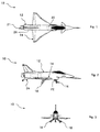
- Aircraft 10 comprises a fuselage 12 and a wing 14 mounted to the fuselage 12.
- a conventional fuselage 12 and wing 14 may be utilized.
- a tricycle landing gear comprising a nose gear 16 and two main gear 18, is attached to the fuselage 12.
- the tricycle landing gear may be designed with a need to withstand only about a 10 ft. per second landing load. This provides a weight reduction over landing gear on aircraft designed to accomplish short landings on aircraft carriers, which are designed to withstand 24 ft. per second landing load.
- a takeoff and landing system enables the aircraft to accomplish extremely short takeoffs and landings (ESTOLs).
- the takeoff and landing systems comprises an integrated flight propulsion control system (IFPCS), including a control system electronics 20 and multi-axis thrust vectoring system (nozzle) 21.
- IFPCS also includes a jump strut 22 or other type of takeoff system; a tail wheel assembly or landing system 24 and a high thrust-to-weight propulsion system 26.
- the vectoring nozzle 21 of the integrated flight propulsion control system may be any one of several types, which provide multi-axis thrust vectoring capability.
- the example shown in Figures 1-3 is a paddle-type nozzle developed by Rockwell International Corporation and Messerschmitt Bölkow Blohn (MBB) for the X-31 Aircraft.
- the jump strut 22 can be any of several existing designs.
- U. S. Patent No. 4,687,158 discloses a possible design. NASA-Technical Memorandum -108819, September 1994, entitled “Flight Investigation of the Use of a Nose Gear Jump Strut to Reduce Takeoff Ground Roll Distance of STOL Aircraft" describes another possible design.
- the high thrust-to-weight propulsion system 26 may be of a conventional type that produces a thrust component, which, when combined with the aerodynamic lift, is equal to, or greater than, the weight of the aircraft 10. To generate this thrust, the engine may or may not have an afterburner.
- main gear 18 has been illustrated as being attached to the fuselage 12, it is understood that it could be alternately attached to the wing.
- the control feedback system electronics of the IFPCS generates the necessary signals to control the deflections of the aerodynamic surfaces (e.g. rudder, ailerons, flaperons, etc.).
- the unit can be any of several commercially available units, such as those currently in F-16 and F-18 aircraft.
- the unit is modified to include signals for thrust vectoring deflections.
- the control law software (which translates pilot stick and rudder commands to control surface deflections) is modified to include thrust deflection and treat it exactly as any of the primary aerodynamic control surfaces. In so doing, the control laws can simultaneously generate an optimum mix of control surface and thrust deflections to maintain aircraft stability during low speed flight.
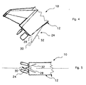
- the tail wheel assembly 24 includes a shock absorbing strut 28, which is attached to the fuselage 12.
- Strut 28 can be of a passive design, or actively controlled by the integrated flight propulsion control system 20, 21 to provide a variable damping force.
- a castoring wheel assembly 30 enables the thrust vectoring system to provide yaw control with the tail wheel assembly in contact with the ground.
- a drag strut 32 connected to the fuselage 12 positions the castoring wheel assembly 30 and transfers the fore and aft loads to the fuselage 12. It could be articulated to facilitate retraction of the tail wheel assembly 30.
- the aircraft 10 is capable of controlled flight at high angles of attack during takeoff and landing. It is, therefore, capable of flying at relatively low speeds. As a consequence, the takeoff and landing distances can be made very short.
- a conventional aircraft will approach at approximately 15° angle of attack, which results in a touchdown speed of 120 kts and a landing distance of 1200 ft.
- An aircraft utilizing the principles of the present invention will approach with a high angle of attack of between about 40° and 70°. This results in touchdown speeds between about 100 kts and 60 kts. These low approach speeds yield landing distances between about 835 ft and 300 ft, which is up to a 75% improvement over conventional aircraft.
- the IFPCS must control the aircraft and provide a substantial portion of the lift needed to support the aircraft in flight.
- the aircraft must de-rotate from a high angle of attack to a main gear touchdown angle of attack sufficiently low to avoid scraping the tall of the aircraft 10.
- the main gear touchdown angle of attack (which is the same in magnitude as the tail scrape angle, see Figure 10) may be typically between about 10° to 30°. (As will be discussed below with respect to another preferred embodiment, the touchdown angle of attack may be made substantially higher).
- Such a de-rotation may be accomplished by use of the tail wheel assembly 24 with the castoring wheel assembly 30.
- yaw control of the aircraft is maintained using the thrust vectoring capability of the IFPCS.
- the thrust vectoring must generate a side-to-side movement of the aircraft tail.
- the tail wheel is in contact with the ground.
- a conventional fixed tail wheel would prevent side-to-side movement of the aircraft tail, while the castoring wheel assembly 30 allows this side-to-side movement.
- the shock absorbing strut 28 of the tail wheel assembly 24 can be of either conventional passive viscous damping construction, or variable damping which is actively controlled by the IFPCS to prevent tail strike, while minimizing the nose down pitch rotation.
- An alternate method for de-rotating the aircraft might comprise a thruster system mounted in proximity to the aircraft nose for providing a jet efflux in the downward direction so as to generate lift and control the rate of de-rotation.
- step 1 the landing gear is extended and the aircraft is pitched up to a high angle of attack, steady-state post stall approach using the IFPCS.
- the aircraft is stabilized on a glide slope of about -4° at a speed between about 60 and 100 kts, so as to provide a rate of descent of 10 ft. per second or less.
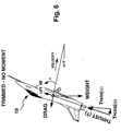
- the aerodynamic control surfaces are ineffective, so stability is maintained with the thrust vectoring system.
- the thrust pitch angle will be very nearly zero, hence no pitching moment will be generated.
- step 2 the aircraft contacts the ground with the tail wheel and the nose begins to rotate down.
- the thrust is vectored from side-to-side (yaw) as needed to maintain the aircraft in a straight line down the runway.
- step 3 the aircraft has rotated down until the main landing gear has contacted the ground. At this point, the thrust is vectored up to slow the rotation of the aircraft Side-to-side vectoring is continued as necessary to control the aircraft.
- step 4 the aircraft has rotated down until the nose landing gear has contacted the ground.
- the anti-lock brakes on the main landing gear are automatically actuated through a switch that senses nose gear ground contact. If a thrust reversing system is employed (not essential for the present invention) it is actuated at this time. Aircraft steering is accomplished using the nose landing gear.
- the most powerful means to achieve a short takeoff distance is to reduce the takeoff speed of the aircraft.
- One way to reduce the takeoff speed is to increase the angle of attack that the aircraft can generate during the takeoff run.
- the analytical discussion that follows will show that a modest 15% increase in the takeoff angle of attack can reduce the takeoff distance by 50%. Utilization of the principles discussed hereinafter can increase the takeoff angle of attack by up to 50%.
- Thrust ⁇ cos( ⁇ + ⁇ T )> C D qS Thrust ⁇ sin( ⁇ T ) ⁇ T ARM C M qS c
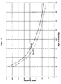
- Figure 13 The relationship between takeoff speed and angle of attack for a typical lightweight fighter is depicted in Figure 13. This shows that takeoff velocity varies approximately with the square of the angle of attack capability of the aircraft. Figure 13 has curves for a thrust deflection of zero and ten degrees down, indicating the benefit of being able to deflect the thrust during takeoff. The maximum allowable thrust deflection is limited by the need to trim the aircraft so that the pitching moment is zero. So the combined trends from Figures 12 and 13 indicate that takeoff distance varies with the fourth power of angle of attack capability.
- FIGS 1-3 show use of a jump strut 22, a ski jump ramp may be used in lieu thereof, or possibly in combination therewith.
- the ski jump ramp works by rotating the velocity vector of the aircraft up and using the aircraft's momentum (rather than aerodynamic force) to lift it off the ground. This principal is exactly the same a human skier going over a bump in the snow and flying into the air, even though he has no wings.
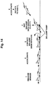
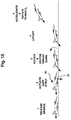
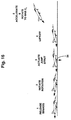
- the aircraft will continue to rotate to a high angle of attack, between about 20° and 50°. In this attitude the thrust will generate a significant portion of the needed lift force with very little thrust vectoring, so the aircraft can remain trimmed.
- the aircraft will be stabilized (controlled) by the IFPCS, which will initially be primarily thrust vectoring. Then as the aircraft accelerates, the aerodynamic control surfaces will seamlessly take over control.
- a takeoff is illustrated utilizing a jump strut 22 on the nose gear.
- the ski jump ramp is not required.
- the advantage of this embodiment is that all the necessary systems are located on the aircraft 10.
- the disadvantage is that this embodiment will generally result in higher takeoff speeds and longer takeoff distances than the first mentioned embodiment.
- the takeoff sequence of events is summarized as follows:
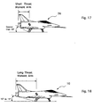
- FIG 17 an alternate aircraft 36 is illustrated in which the thrust moment arm is significantly reduced.
- the thrust moment arm is the distance between the aircraft center of gravity and the vectoring nozzle.
- Figure 18 shows the aircraft 10 of Figures 1-3 and 9-10, for the purposes of comparison.
- Aircraft 10 has a conventional relatively long thrust moment arm.
- the reduced thrust moment arm allows the thrust to be vectored down more, generating additional lift, without generating a large pitching moment that must be trimmed out. This enables an aircraft configured in this manner to takeoff and land at the same speed, but at a lower angle of attack.
- An aircraft configured as shown in Figure 17 has the main landing gear located slightly behind the center of gravity.
- the shorter thrust moment arm results in a substantially increased tail scrape angle of 30° or greater.
- the increased tail scrape angle allows the aircraft to rotate to a higher angle of attack during takeoff and landing.
- the combination of a significantly reduced thrust moment arm and significantly increased tail scrape angle can eliminate the need for a tail wheel, jump struts, and/or ski jump ramp.
- the disadvantage of this embodiment is that numerous other design constraints may prevent the thrust moment arm from being reduced or the tail scrape angle from being increased sufficiently to allow extremely short takeoffs and landings.
- the invention relates to a system for enabling an aircraft to accomplish extremely short takeoffs and landings, comprising: an integrated flight propulsion control system comprising a multi-axis thrust vectoring system; and a takeoff system operably engageable with said multi-axis thrust vectoring system.
Landscapes
- Engineering & Computer Science (AREA)
- Chemical & Material Sciences (AREA)
- Combustion & Propulsion (AREA)
- Aviation & Aerospace Engineering (AREA)
- Mechanical Engineering (AREA)
- General Engineering & Computer Science (AREA)
- Transmission Devices (AREA)
- Retarders (AREA)
Applications Claiming Priority (2)
| Application Number | Priority Date | Filing Date | Title |
|---|---|---|---|
| US867656 | 1997-06-02 | ||
| US08/867,656 US5984229A (en) | 1997-06-02 | 1997-06-02 | Extremely short takeoff and landing of aircraft using multi-axis thrust vectoring |
Publications (3)
| Publication Number | Publication Date |
|---|---|
| EP0882647A2 true EP0882647A2 (fr) | 1998-12-09 |
| EP0882647A3 EP0882647A3 (fr) | 1999-11-24 |
| EP0882647B1 EP0882647B1 (fr) | 2005-07-27 |
Family
ID=25350218
Family Applications (1)
| Application Number | Title | Priority Date | Filing Date |
|---|---|---|---|
| EP98109745A Expired - Lifetime EP0882647B1 (fr) | 1997-06-02 | 1998-05-28 | Décolage et atterrissage extrêmement courts d'un avion utilisant une régulation multiaxe du vecteur de poussée |
Country Status (3)
| Country | Link |
|---|---|
| US (1) | US5984229A (fr) |
| EP (1) | EP0882647B1 (fr) |
| DE (1) | DE69830953T2 (fr) |
Cited By (2)
| Publication number | Priority date | Publication date | Assignee | Title |
|---|---|---|---|---|
| GB2343425A (en) * | 1998-10-30 | 2000-05-10 | Lockheed Corp | Rapid turning and manoeuvring of a vehicle in a fluid stream using a propulsive thrust |
| CN114542323A (zh) * | 2021-12-29 | 2022-05-27 | 中国航空工业集团公司沈阳飞机设计研究所 | 一种矢量喷管的控制方法及装置 |
Families Citing this family (23)
| Publication number | Priority date | Publication date | Assignee | Title |
|---|---|---|---|---|
| US6513754B1 (en) | 2001-09-26 | 2003-02-04 | The United States Of America As Represented By The Secretary Of The Navy | Transonic flow shockwave position stabilizer |
| US6814330B2 (en) * | 2002-12-12 | 2004-11-09 | The Boeing Company | Method and computer program product for controlling the control effectors of an aerodynamic vehicle |
| US7004428B2 (en) * | 2003-01-24 | 2006-02-28 | Aerion Corporation | Lift and twist control using trailing edge control surfaces on supersonic laminar flow wings |
| US6845944B2 (en) * | 2003-04-11 | 2005-01-25 | The Boeing Company | Multi-positional tail skids and associated methods of use |
| US7997528B2 (en) * | 2006-01-18 | 2011-08-16 | Aereon Corporation | Reducing runway requirement for aircraft |
| US7410122B2 (en) * | 2006-03-20 | 2008-08-12 | The Boeing Company | VTOL UAV with lift fans in joined wings |
| US7837141B2 (en) * | 2006-03-22 | 2010-11-23 | The Boeing Company | Reaction drive rotor/wing variable area nozzle |
| JP5046100B2 (ja) * | 2007-07-24 | 2012-10-10 | 独立行政法人 宇宙航空研究開発機構 | 短距離離着陸航空機 |
| US8615335B2 (en) * | 2008-09-17 | 2013-12-24 | The Boeing Company | Progressive takeoff thrust ramp for an aircraft |
| NL2002064C (nl) * | 2008-10-07 | 2010-04-08 | Robertus Gerardus De Boer | Gedifferentieerde stuwkracht startmethode voor een vliegtuig. |
| US9067675B2 (en) * | 2013-01-08 | 2015-06-30 | The Boeing Company | Airplane emergency supplemental braking system and method |
| US10464668B2 (en) | 2015-09-02 | 2019-11-05 | Jetoptera, Inc. | Configuration for vertical take-off and landing system for aerial vehicles |
| EP4306789A3 (fr) | 2015-09-02 | 2024-06-12 | Jetoptera, Inc. | Système propulsif fluidique |
| US11001378B2 (en) | 2016-08-08 | 2021-05-11 | Jetoptera, Inc. | Configuration for vertical take-off and landing system for aerial vehicles |
| CN105438486B (zh) * | 2015-12-11 | 2017-06-16 | 中国航空工业集团公司西安飞机设计研究所 | 一种机身尾部保护系统 |
| CN105752322A (zh) * | 2016-04-19 | 2016-07-13 | 上海交通大学 | 一种电驱动起落架系统及含有该系统的飞行器 |
| US10247573B1 (en) * | 2017-03-29 | 2019-04-02 | Rockwell Collins, Inc. | Guidance system and method for low visibility takeoff |
| CA3068569A1 (fr) | 2017-06-27 | 2019-01-03 | Jetoptera, Inc. | Configuration pour systeme de decollage et d'atterrissage vertical pour vehicules aeriens |
| US20190185127A1 (en) * | 2017-12-18 | 2019-06-20 | Freedom Aircraft Ventures Llc | Aircraft design and technology |
| US11167836B2 (en) | 2018-06-21 | 2021-11-09 | Sierra Nevada Corporation | Devices and methods to attach composite core to a surrounding structure |
| WO2019245599A1 (fr) | 2018-06-21 | 2019-12-26 | Sierra Nevada Corporation | Jonction d'âmes composites en bord de treillis pour aile d'aéronef |
| US12391371B2 (en) * | 2022-10-03 | 2025-08-19 | Jetzero, Inc. | Aircraft with outboard-stowed landing gear |
| CN117452973B (zh) * | 2023-12-22 | 2024-03-19 | 中国航空工业集团公司西安飞机设计研究所 | 一种运输机前线机场短距着陆航迹优化方法及装置 |
Citations (9)
| Publication number | Priority date | Publication date | Assignee | Title |
|---|---|---|---|---|
| US2761634A (en) | 1955-01-20 | 1956-09-04 | Jose L Velazquez | Verttcally rising airplane |
| US2971725A (en) | 1954-12-31 | 1961-02-14 | Sud Est Aviat Soc Nat De Const | Aircraft take-off and landing apparatus |
| US3995794A (en) | 1975-06-24 | 1976-12-07 | Lanier Edward M | Super-short take off and landing apparatus |
| US4261533A (en) | 1978-06-26 | 1981-04-14 | Dynamic Engineering, Inc. | All-axis control of aircraft in ultra deep stall |
| US4687158A (en) | 1985-07-15 | 1987-08-18 | Lockheed Corporation | Jump strut landing gear apparatus and system |
| US4896846A (en) | 1985-04-09 | 1990-01-30 | Dynamic Engineering, Inc. | Superagile tactical fighter aircraft and method of flying it in supernormal flight |
| US5098034A (en) | 1989-11-24 | 1992-03-24 | Lendriet William C | Vertical/short takeoff or landing aircraft having a rotatable wing and tandem supporting surfaces |
| US5351888A (en) | 1993-05-14 | 1994-10-04 | General Electric Company | Multi-axis vectorable exhaust nozzle |
| USRE35387E (en) | 1985-04-09 | 1996-12-03 | Dynamic Engineering, Inc. | Superfragile tactical fighter aircraft and method of flying it in supernormal flight |
Family Cites Families (10)
| Publication number | Priority date | Publication date | Assignee | Title |
|---|---|---|---|---|
| US35387A (en) * | 1862-05-27 | Improvement in rice cleaning, hulling, and pearling machines | ||
| US3089667A (en) * | 1959-05-02 | 1963-05-14 | Junkers Flugzeng Und Motorenwe | Jet aircraft for short take-off and landing distances |
| GB927408A (en) * | 1960-11-28 | 1963-05-29 | Secr Aviation | Improvements in and relating to aircraft undercarriages |
| US4099687A (en) * | 1976-07-22 | 1978-07-11 | Roberts Lawrence T | All-axis control of aircraft in deep stall |
| GB1554968A (en) * | 1977-01-13 | 1979-10-31 | Hawker Siddeley Aviation Ltd | Aircraft launching techniques |
| US4506848A (en) * | 1980-12-22 | 1985-03-26 | British Aerospace Public Limited Company | Aircraft configuration and control arrangement therefor |
| US4482109A (en) * | 1981-06-04 | 1984-11-13 | Dupont Anthony A | Jet aircraft |
| US4456203A (en) * | 1982-08-02 | 1984-06-26 | Ltv Aerospace And Defense Company | Aircraft propulsion system having a translatable, directionable exhaust nozzle |
| US4524929A (en) * | 1982-09-30 | 1985-06-25 | Grumman Aerospace Corporation | Short take off jump mode for airplane landing gear struts |
| US5062588A (en) * | 1989-02-08 | 1991-11-05 | Boeing Of Canada Ltd. | Segmented rotatable nozzles |
-
1997
- 1997-06-02 US US08/867,656 patent/US5984229A/en not_active Expired - Fee Related
-
1998
- 1998-05-28 DE DE69830953T patent/DE69830953T2/de not_active Expired - Lifetime
- 1998-05-28 EP EP98109745A patent/EP0882647B1/fr not_active Expired - Lifetime
Patent Citations (9)
| Publication number | Priority date | Publication date | Assignee | Title |
|---|---|---|---|---|
| US2971725A (en) | 1954-12-31 | 1961-02-14 | Sud Est Aviat Soc Nat De Const | Aircraft take-off and landing apparatus |
| US2761634A (en) | 1955-01-20 | 1956-09-04 | Jose L Velazquez | Verttcally rising airplane |
| US3995794A (en) | 1975-06-24 | 1976-12-07 | Lanier Edward M | Super-short take off and landing apparatus |
| US4261533A (en) | 1978-06-26 | 1981-04-14 | Dynamic Engineering, Inc. | All-axis control of aircraft in ultra deep stall |
| US4896846A (en) | 1985-04-09 | 1990-01-30 | Dynamic Engineering, Inc. | Superagile tactical fighter aircraft and method of flying it in supernormal flight |
| USRE35387E (en) | 1985-04-09 | 1996-12-03 | Dynamic Engineering, Inc. | Superfragile tactical fighter aircraft and method of flying it in supernormal flight |
| US4687158A (en) | 1985-07-15 | 1987-08-18 | Lockheed Corporation | Jump strut landing gear apparatus and system |
| US5098034A (en) | 1989-11-24 | 1992-03-24 | Lendriet William C | Vertical/short takeoff or landing aircraft having a rotatable wing and tandem supporting surfaces |
| US5351888A (en) | 1993-05-14 | 1994-10-04 | General Electric Company | Multi-axis vectorable exhaust nozzle |
Non-Patent Citations (3)
| Title |
|---|
| "nasa-technical memorandum-108819", September 1994, article "flight investigation of the use of a nose gear jump strut to reduce takeoff ground roll distance of stol aircraft" |
| "society of automotive engineers , inc. paper 872383", 1988, article "the f-15 stol and maneuver technology demonstrator (s/mtd) program" |
| JOHN W. FOZARD: "the jet v/stol harrier", July 1978, article BRITISH AEROSPACE AIRCRAFT GROUP, pages: 122 - 159 |
Cited By (5)
| Publication number | Priority date | Publication date | Assignee | Title |
|---|---|---|---|---|
| GB2343425A (en) * | 1998-10-30 | 2000-05-10 | Lockheed Corp | Rapid turning and manoeuvring of a vehicle in a fluid stream using a propulsive thrust |
| US6308911B1 (en) | 1998-10-30 | 2001-10-30 | Lockheed Martin Corp. | Method and apparatus for rapidly turning a vehicle in a fluid medium |
| GB2343425B (en) * | 1998-10-30 | 2003-01-15 | Lockheed Corp | Method and apparatus for rapidly turning a vehicle in a fluid medium |
| CN114542323A (zh) * | 2021-12-29 | 2022-05-27 | 中国航空工业集团公司沈阳飞机设计研究所 | 一种矢量喷管的控制方法及装置 |
| CN114542323B (zh) * | 2021-12-29 | 2023-11-28 | 中国航空工业集团公司沈阳飞机设计研究所 | 一种矢量喷管的控制方法及装置 |
Also Published As
| Publication number | Publication date |
|---|---|
| EP0882647A3 (fr) | 1999-11-24 |
| DE69830953T2 (de) | 2006-03-23 |
| DE69830953D1 (de) | 2005-09-01 |
| US5984229A (en) | 1999-11-16 |
| EP0882647B1 (fr) | 2005-07-27 |
Similar Documents
| Publication | Publication Date | Title |
|---|---|---|
| EP0882647B1 (fr) | Décolage et atterrissage extrêmement courts d'un avion utilisant une régulation multiaxe du vecteur de poussée | |
| US12006030B2 (en) | Distributed electric propulsion modular wing aircraft with blown wing and extreme flaps for VTOL and/or STOL flight | |
| EP0629164B1 (fr) | Aeronef a ailes libres a poussee vectorisee | |
| US4896846A (en) | Superagile tactical fighter aircraft and method of flying it in supernormal flight | |
| US7410122B2 (en) | VTOL UAV with lift fans in joined wings | |
| US6655631B2 (en) | Personal hoverplane with four tiltmotors | |
| US4721271A (en) | Devices and method for rocket booster vectoring to provide stability augmentation during a booster launch phase | |
| US9851723B2 (en) | Method and apparatus for flight control of tiltrotor aircraft | |
| US8616492B2 (en) | Three wing, six tilt-propulsion units, VTOL aircraft | |
| US5086993A (en) | Airplane with variable-incidence wing | |
| US8708273B2 (en) | Three-wing, six tilt-propulsion unit, VTOL aircraft | |
| Anderson | Historical overview of V/STOL aircraft technology | |
| US7118066B2 (en) | Tall V/STOL aircraft | |
| US20120091257A1 (en) | Air vehicle | |
| USRE35387E (en) | Superfragile tactical fighter aircraft and method of flying it in supernormal flight | |
| USRE36487E (en) | Airplane with variable-incidence wing | |
| US20070215751A1 (en) | Asymmetrical VTOL UAV | |
| WO2012047337A1 (fr) | Avion adav à trois ailes et six unités de propulsion inclinables | |
| US3114520A (en) | Stabilization and control system for pilotless, vertical take-off and landing aircraft | |
| US2743886A (en) | Vertical climbing airplane | |
| Nagabhushan et al. | Thrust-vectored takeoff, landing, and ground handling of an airship | |
| RU2192986C2 (ru) | Самолет павловых | |
| Gerdes | Lift-fan aircraft-Lessons learned from XV-5 flight experience | |
| RU2321526C1 (ru) | Многоразовый ускоритель ракеты-носителя | |
| RU2852394C1 (ru) | Преобразуемый дозвуковой самолет |
Legal Events
| Date | Code | Title | Description |
|---|---|---|---|
| PUAI | Public reference made under article 153(3) epc to a published international application that has entered the european phase |
Free format text: ORIGINAL CODE: 0009012 |
|
| AK | Designated contracting states |
Kind code of ref document: A2 Designated state(s): DE ES FR GB SE |
|
| AX | Request for extension of the european patent |
Free format text: AL;LT;LV;MK;RO;SI |
|
| PUAL | Search report despatched |
Free format text: ORIGINAL CODE: 0009013 |
|
| AK | Designated contracting states |
Kind code of ref document: A3 Designated state(s): AT BE CH CY DE DK ES FI FR GB GR IE IT LI LU MC NL PT SE |
|
| AX | Request for extension of the european patent |
Free format text: AL;LT;LV;MK;RO;SI |
|
| RIC1 | Information provided on ipc code assigned before grant |
Free format text: 6B 64C 39/00 A, 6B 64C 25/00 B, 6F 02K 1/00 B, 6B 64C 15/02 B |
|
| 17P | Request for examination filed |
Effective date: 20000420 |
|
| AKX | Designation fees paid |
Free format text: DE ES FR GB SE |
|
| 17Q | First examination report despatched |
Effective date: 20020709 |
|
| GRAP | Despatch of communication of intention to grant a patent |
Free format text: ORIGINAL CODE: EPIDOSNIGR1 |
|
| GRAS | Grant fee paid |
Free format text: ORIGINAL CODE: EPIDOSNIGR3 |
|
| GRAA | (expected) grant |
Free format text: ORIGINAL CODE: 0009210 |
|
| AK | Designated contracting states |
Kind code of ref document: B1 Designated state(s): DE ES FR GB SE |
|
| REG | Reference to a national code |
Ref country code: GB Ref legal event code: FG4D |
|
| REF | Corresponds to: |
Ref document number: 69830953 Country of ref document: DE Date of ref document: 20050901 Kind code of ref document: P |
|
| REG | Reference to a national code |
Ref country code: SE Ref legal event code: TRGR |
|
| ET | Fr: translation filed | ||
| PG25 | Lapsed in a contracting state [announced via postgrant information from national office to epo] |
Ref country code: SE Free format text: LAPSE BECAUSE OF NON-PAYMENT OF DUE FEES Effective date: 20060529 |
|
| PLBE | No opposition filed within time limit |
Free format text: ORIGINAL CODE: 0009261 |
|
| STAA | Information on the status of an ep patent application or granted ep patent |
Free format text: STATUS: NO OPPOSITION FILED WITHIN TIME LIMIT |
|
| 26N | No opposition filed |
Effective date: 20060428 |
|
| EUG | Se: european patent has lapsed | ||
| PG25 | Lapsed in a contracting state [announced via postgrant information from national office to epo] |
Ref country code: ES Free format text: LAPSE BECAUSE OF NON-PAYMENT OF DUE FEES Effective date: 20060531 |
|
| REG | Reference to a national code |
Ref country code: FR Ref legal event code: PLFP Year of fee payment: 19 |
|
| PGFP | Annual fee paid to national office [announced via postgrant information from national office to epo] |
Ref country code: DE Payment date: 20160527 Year of fee payment: 19 Ref country code: GB Payment date: 20160527 Year of fee payment: 19 |
|
| PGFP | Annual fee paid to national office [announced via postgrant information from national office to epo] |
Ref country code: FR Payment date: 20160530 Year of fee payment: 19 |
|
| REG | Reference to a national code |
Ref country code: DE Ref legal event code: R119 Ref document number: 69830953 Country of ref document: DE |
|
| GBPC | Gb: european patent ceased through non-payment of renewal fee |
Effective date: 20170528 |
|
| REG | Reference to a national code |
Ref country code: FR Ref legal event code: ST Effective date: 20180131 |
|
| PG25 | Lapsed in a contracting state [announced via postgrant information from national office to epo] |
Ref country code: DE Free format text: LAPSE BECAUSE OF NON-PAYMENT OF DUE FEES Effective date: 20171201 Ref country code: GB Free format text: LAPSE BECAUSE OF NON-PAYMENT OF DUE FEES Effective date: 20170528 |
|
| PG25 | Lapsed in a contracting state [announced via postgrant information from national office to epo] |
Ref country code: FR Free format text: LAPSE BECAUSE OF NON-PAYMENT OF DUE FEES Effective date: 20170531 |