EP0882679A1 - Procédé et four de fusion pour la vitrification de déchets contenant des métaux lourds - Google Patents
Procédé et four de fusion pour la vitrification de déchets contenant des métaux lourds Download PDFInfo
- Publication number
- EP0882679A1 EP0882679A1 EP98810463A EP98810463A EP0882679A1 EP 0882679 A1 EP0882679 A1 EP 0882679A1 EP 98810463 A EP98810463 A EP 98810463A EP 98810463 A EP98810463 A EP 98810463A EP 0882679 A1 EP0882679 A1 EP 0882679A1
- Authority
- EP
- European Patent Office
- Prior art keywords
- furnace
- melt
- fraction
- discharge
- main
- Prior art date
- Legal status (The legal status is an assumption and is not a legal conclusion. Google has not performed a legal analysis and makes no representation as to the accuracy of the status listed.)
- Withdrawn
Links
Images
Classifications
-
- C—CHEMISTRY; METALLURGY
- C03—GLASS; MINERAL OR SLAG WOOL
- C03B—MANUFACTURE, SHAPING, OR SUPPLEMENTARY PROCESSES
- C03B5/00—Melting in furnaces; Furnaces so far as specially adapted for glass manufacture
- C03B5/16—Special features of the melting process; Auxiliary means specially adapted for glass-melting furnaces
- C03B5/235—Heating the glass
-
- C—CHEMISTRY; METALLURGY
- C03—GLASS; MINERAL OR SLAG WOOL
- C03B—MANUFACTURE, SHAPING, OR SUPPLEMENTARY PROCESSES
- C03B3/00—Charging the melting furnaces
-
- C—CHEMISTRY; METALLURGY
- C03—GLASS; MINERAL OR SLAG WOOL
- C03B—MANUFACTURE, SHAPING, OR SUPPLEMENTARY PROCESSES
- C03B5/00—Melting in furnaces; Furnaces so far as specially adapted for glass manufacture
- C03B5/005—Melting in furnaces; Furnaces so far as specially adapted for glass manufacture of glass-forming waste materials
-
- C—CHEMISTRY; METALLURGY
- C03—GLASS; MINERAL OR SLAG WOOL
- C03B—MANUFACTURE, SHAPING, OR SUPPLEMENTARY PROCESSES
- C03B5/00—Melting in furnaces; Furnaces so far as specially adapted for glass manufacture
- C03B5/02—Melting in furnaces; Furnaces so far as specially adapted for glass manufacture in electric furnaces, e.g. by dielectric heating
- C03B5/027—Melting in furnaces; Furnaces so far as specially adapted for glass manufacture in electric furnaces, e.g. by dielectric heating by passing an electric current between electrodes immersed in the glass bath, i.e. by direct resistance heating
- C03B5/03—Tank furnaces
-
- C—CHEMISTRY; METALLURGY
- C03—GLASS; MINERAL OR SLAG WOOL
- C03B—MANUFACTURE, SHAPING, OR SUPPLEMENTARY PROCESSES
- C03B5/00—Melting in furnaces; Furnaces so far as specially adapted for glass manufacture
- C03B5/02—Melting in furnaces; Furnaces so far as specially adapted for glass manufacture in electric furnaces, e.g. by dielectric heating
- C03B5/033—Melting in furnaces; Furnaces so far as specially adapted for glass manufacture in electric furnaces, e.g. by dielectric heating by using resistance heaters above or in the glass bath, i.e. by indirect resistance heating
- C03B5/0332—Tank furnaces
-
- C—CHEMISTRY; METALLURGY
- C03—GLASS; MINERAL OR SLAG WOOL
- C03B—MANUFACTURE, SHAPING, OR SUPPLEMENTARY PROCESSES
- C03B5/00—Melting in furnaces; Furnaces so far as specially adapted for glass manufacture
- C03B5/16—Special features of the melting process; Auxiliary means specially adapted for glass-melting furnaces
- C03B5/26—Outlets, e.g. drains, siphons; Overflows, e.g. for supplying the float tank, tweels
- C03B5/262—Drains, i.e. means to dump glass melt or remove unwanted materials
-
- C—CHEMISTRY; METALLURGY
- C03—GLASS; MINERAL OR SLAG WOOL
- C03B—MANUFACTURE, SHAPING, OR SUPPLEMENTARY PROCESSES
- C03B5/00—Melting in furnaces; Furnaces so far as specially adapted for glass manufacture
- C03B5/16—Special features of the melting process; Auxiliary means specially adapted for glass-melting furnaces
- C03B5/26—Outlets, e.g. drains, siphons; Overflows, e.g. for supplying the float tank, tweels
- C03B5/265—Overflows; Lips; Tweels
-
- Y—GENERAL TAGGING OF NEW TECHNOLOGICAL DEVELOPMENTS; GENERAL TAGGING OF CROSS-SECTIONAL TECHNOLOGIES SPANNING OVER SEVERAL SECTIONS OF THE IPC; TECHNICAL SUBJECTS COVERED BY FORMER USPC CROSS-REFERENCE ART COLLECTIONS [XRACs] AND DIGESTS
- Y02—TECHNOLOGIES OR APPLICATIONS FOR MITIGATION OR ADAPTATION AGAINST CLIMATE CHANGE
- Y02P—CLIMATE CHANGE MITIGATION TECHNOLOGIES IN THE PRODUCTION OR PROCESSING OF GOODS
- Y02P40/00—Technologies relating to the processing of minerals
- Y02P40/50—Glass production, e.g. reusing waste heat during processing or shaping
- Y02P40/57—Improving the yield, e-g- reduction of reject rates
Definitions
- the invention relates to a method for glazing heavy metals Residues with a chlorine content from flue gas cleaning of more than 10 mass%, especially filter dust and residues from flue gas scrubbing, in which the residues are melted in a melting furnace and are then discharged, with the purpose of conditioning the melt Additives can be added, as well as a melting furnace for implementation of the procedure.
- a method of this type is for example from the DE 43 40 754 A1 is known, and a deglor oven is described, for example, in EP 0 633 411 A1 described.
- the Deglor process has been used for the glazing of residues small content of metal chlorides, metal sulfates and metal sulfites as they typically present in the filter dust, well proven.
- the filter ash is mixed with the highly chlorine-containing product of flue gas cleaning.
- the exhaust gases are subjected to lime washing, calcium compounds, in particular CaSO 3 , Ca SO 4 and CaCl 2 , being produced as by-products, which are to be melted and glazed together with the filter ash.
- this product contains 10 to 20% by mass of chlorine, predominantly in the form of CaCl 2 .
- This compound has a boiling point (> 1600 ° C) that is far above the usual operating temperatures. As a result, these chlorides cannot be converted into the vapor phase effectively enough. At the same time, only a small part of chlorine can be incorporated into the glass.
- Another disadvantage is that due to the additional additives required, the additional amount of exhaust gas as well as the larger amount to be evaporated Material of the energy requirement of the Deglor plant increases.
- alkali-containing reagents such as NaHCO 3
- flue gas cleaning instead of lime, alkali-containing reagents, such as NaHCO 3 , are used for flue gas cleaning, as a result of which it is no longer necessary to add alkali-containing additives to the melting furnace in order to increase the evaporation rate of the chlorides.
- the invention tries to avoid all of these disadvantages.
- You have the task based, a method and an apparatus for vitrifying heavy metal Residues with high chlorine content from flue gas cleaning of the above Specify the type in which the amount of required alkali-containing additives is reduced is, and the throughput of residues can be increased.
- the required electrical power and the amount of exhaust gas are reduced so that lower overall operating costs.
- a more economical Heavy metals can be recovered from the condensate.
- this is achieved in that in a method according to the preamble of claim 1, in the main furnace, which cannot be integrated into the melt Components of the residues are separated into two fractions, whereby the first fraction the volatile components and the second fraction the contains salt-like, less volatile components, and the first fraction evaporated, led out of the furnace with the exhaust gas and collected as condensate and the second fraction as liquid salt from the surface of the Melt is separated and discharged.
- the invention is based on the unexpected finding that when the melting plant according to DE 196 03 365.9 is operated, a stable, thin layer of salt can form on the surface of the glass-like melt, which layer consists practically exclusively of CaCl 2 , NaCl and KCl and in particular one compared to that Condensate contains a smaller concentration of heavy metals. According to the invention, the entire salt is no longer evaporated together with the other volatile constituents of the residue.
- this is carried out in a melting furnace for carrying out the method achieved according to the preamble of claim 8 in that in the outer wall the main furnace has a side outlet for that on the glass melt floating salt is provided.
- the lower edge of this side opening is in a height of approx. 1 to 10 cm above that determined by the outlet stone Melting levels arranged.
- the advantages of the invention include that the condensate is heavily enriched with heavy metals that a reprocessing purpose Heavy metal recovery is worthwhile again.
- Compared to the known state of the Technology can also reduce the amount of alkaline additives and the furnace temperature can be reduced, so that on the one hand the life span the furnace parts are extended and on the other hand the required electrical Performance can be reduced. There is a significant increase in Throughput of residual material, so that overall the operating costs of the plant are reduced will.
- a mass ratio between the first Fraction, i.e. the condensate, and the second fraction, i.e. the liquid salt is set, which depends on the composition of the residue is in the range of 0.1 to 10.
- the size of the mass ratio between the first and the second fraction is determined by the choice of process parameters, preferably temperature, amount of exhaust gas and amount of alkali-containing additives, set. It is important that the evaporation of the salt, i.e. the second fraction, is restricted. This happens, for example, by the amount of exhaust gas and / or the temperature above the melt or the amount of alkali-containing additives can be reduced.
- layer thicknesses in the upper Area advantageous if the residues with high production rates in the Melting furnace can be fed.
- the in the main furnace for the purpose of controlling the Exhaust gas volume from the furnace additionally introduced air before entering the main furnace is preheated by the liquid salt flowing from the main oven.
- the amount of flue gas from the furnace is adjusted by the amount of supply air thus the proportion of the evaporated components is also determined.
- the opening for the salt discharge in the melting furnace is arranged near the partition between the main and discharge furnace. This prevents the discharged salt from being unmelted Residue is contaminated.
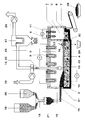
- the single figure shows a schematic representation of the furnace and the front or. downstream units.
- the figure shows schematically a melting furnace 1, which consists of a main furnace 2 a melting tank 3 located in the lower part for receiving the Melt 4 and consists of a discharge furnace 5.
- the discharge furnace 5 is with the The melting tank 3 is connected via a siphon 30 and by means of a partition 6 separated from the main oven 2.
- the discharge furnace 5 is an overflow as a discharge device 7 with a discharge stone 8 arranged to discharge the glass melt 4.
- a first heater in the form of electrical heating elements 9, which of ceramic protective tubes are surrounded, protrudes from above into the gas space 10 of the main furnace 2, without being immersed in the melt 4.
- a second heater in the form of electric heating elements 11 also protrude from above into the discharge furnace 5, without touching the melt 4.
- a removal device 13 for the exhaust gas 14 is also provided.
- an inlet 31 is arranged, which is above the Levels of melt 4 is located.
- the feed is carried out by means of a loading device 15, for example a screw conveyor.
- Such a melting furnace is the subject of EP 0 633 441 A1, to which hereby expressly referred to avoid repetition becomes.
- the opening 16 there is a side opening in the outer wall of the main furnace 2 16 arranged, which is provided for a salt discharge to be described is.
- the underside of the opening 16 is at a height of approximately 1 to 10 cm above the level of the melting level, which when operating the furnace without Salt layer arises. This melting level is approximately at the level of the outlet stone 8.
- the opening 16 can also be used simultaneously for the Dosing of supply air 17 can be used.
- the additives are essentially needed to get out of the residue 18 to produce easily meltable and stable glass. Not with the invention more all chlorine-containing constituents of the residues are evaporated off more , the additives containing alhali according to DE 196 03 365.9 are not more required or can be used in a much smaller dose.
- the proportion of volatile components which are evaporated and collected as condensate, in particular heavy metal chlorides (first fraction 22) and the proportion of salt-like components which are in the form of liquid Salt 23 (second fraction) is separated from the melt 4 and discharged through the opening 16 either continuously or batchwise and collected in a container 24.
- the second fraction 23 contains the less volatile components, in particular CaCl 2 , NaCl and KCl.
- the melt 4 is continuously or intermittently from the discharge furnace 5 withdrawn and deposited or processed as a glass-like product 29.
- the exhaust gases 14 from the melting furnace including the evaporated first fraction 22 are sucked out of the melting furnace by means of a fan 25 and cooled with cold air 26 (quenched). This will condense and desublimate them Heavy metal compounds from the gas and can be downstream Filters, e.g. Bag filter 27, separated as condensate 28 and processed later will.
- the filtered air can, for example, go to the waste incineration plant to be led back.
- the condensate 28 Due to the different evaporation characteristics between the two fractions 22 and 23, the generally more volatile heavy metals, such as Pb, which go into the condensate 28 are separated from the hardly volatile NaCl, KCl and CaCl 2 , which are mainly to be discharged as salt.
- the condensate 28 is now so heavily enriched with heavy metals that it is worth working up again for the purpose of recovering heavy metals.
- the mass ratio of Condensate 28 and liquid salt 23 are between 0.1 and 10.
- the thickness of the salt layer 23 should be larger than 1 cm to ensure a clean separation from the one below Ensure glass melt 4. Layer thicknesses are preferably between To aim for 3 and 10 cm. Larger values are then particularly of Advantage if the residues 18 are fed into the melting furnace 1 at high feed rates will.
- the lateral opening 16 now forms one Overflow for the salt 23 floating on the surface of the melt 4, the can be collected in a laterally attached container 24. To this This enables continuous operation of the system. So that is carried out Salt is not contaminated by unmelted residues 18, it is expedient, the opening 16 for the salt discharge near the partition 6 between to arrange the main furnace 2 and the discharge furnace 5.
- the opening 16 can at the same time for metering supply air 17 into the main furnace be used.
- the amount of exhaust gas 14 is determined by the amount of supply air 17 set out of the oven and thus the proportion of evaporated components co-determined. It is favorable if the hot salt flowing out of the opening 16 23 is used to preheat the supply air 17.
Landscapes
- Chemical & Material Sciences (AREA)
- Engineering & Computer Science (AREA)
- Materials Engineering (AREA)
- Organic Chemistry (AREA)
- Chemical Kinetics & Catalysis (AREA)
- Electrochemistry (AREA)
- Processing Of Solid Wastes (AREA)
- Gasification And Melting Of Waste (AREA)
Applications Claiming Priority (2)
| Application Number | Priority Date | Filing Date | Title |
|---|---|---|---|
| DE19723599 | 1997-06-05 | ||
| DE19723599A DE19723599A1 (de) | 1997-06-05 | 1997-06-05 | Verfahren zum Verglasen von schwermetallhaltigen Reststoffen mit einem über 10 Massen-% liegenden Chlorgehalt sowie Schmelzofen zur Durchführung des Verfahrens |
Publications (1)
| Publication Number | Publication Date |
|---|---|
| EP0882679A1 true EP0882679A1 (fr) | 1998-12-09 |
Family
ID=7831497
Family Applications (1)
| Application Number | Title | Priority Date | Filing Date |
|---|---|---|---|
| EP98810463A Withdrawn EP0882679A1 (fr) | 1997-06-05 | 1998-05-19 | Procédé et four de fusion pour la vitrification de déchets contenant des métaux lourds |
Country Status (4)
| Country | Link |
|---|---|
| US (2) | US6315810B1 (fr) |
| EP (1) | EP0882679A1 (fr) |
| JP (1) | JPH115069A (fr) |
| DE (1) | DE19723599A1 (fr) |
Cited By (2)
| Publication number | Priority date | Publication date | Assignee | Title |
|---|---|---|---|---|
| EP0955271A3 (fr) * | 1998-04-28 | 2000-04-26 | Beteiligungen Sorg GmbH & Co. KG | Procédé et disposition pour la fusion de verre dans des fours à bassin à flammes en forme de "U" ou transversales pour réduire la concentration en NOx et en CO dans les fumées de gaz |
| CN108500026A (zh) * | 2017-02-24 | 2018-09-07 | 永续发展股份有限公司 | 利用周波及电浆的废弃物玻璃化处理方法及设备 |
Families Citing this family (9)
| Publication number | Priority date | Publication date | Assignee | Title |
|---|---|---|---|---|
| US6620092B2 (en) * | 2001-05-11 | 2003-09-16 | Chem Pro | Process and apparatus for vitrification of hazardous waste materials |
| KR20030027189A (ko) * | 2001-09-14 | 2003-04-07 | 김명식 | 칸탈을 이용한 유리 제조용 전기용해로 및 이전기용해로를 이용한 유리제조방법 |
| US7211038B2 (en) * | 2001-09-25 | 2007-05-01 | Geosafe Corporation | Methods for melting of materials to be treated |
| EP1841700A1 (fr) * | 2005-01-28 | 2007-10-10 | Geosafe Corporation | Matiere de couverture utilisee pour la vitrification dans le conteneur |
| FR2881820B1 (fr) * | 2005-02-10 | 2008-05-30 | Saint Gobain Vetrotex | Dispositif pour l'extraction de chaleur a partir de gaz et pour la recuperation des condensats |
| CN101830629B (zh) * | 2010-03-22 | 2013-01-02 | 中国南玻集团股份有限公司 | 玻璃窑热循环节能系统 |
| DE102010035893B3 (de) * | 2010-08-31 | 2012-01-19 | Beteiligungen Sorg Gmbh & Co. Kg | Beschickungsvorrichtung für Glasschmelzanlagen und Verfahren zum Einlegen von partikelförmigem Beschickungsgut |
| JP6011451B2 (ja) * | 2013-05-14 | 2016-10-19 | 日本電気硝子株式会社 | フィーダー |
| WO2016048956A1 (fr) * | 2014-09-24 | 2016-03-31 | Corning Incorporated | Systèmes de filtration volatile destinés à des machines d'étirage par fusion |
Citations (10)
| Publication number | Priority date | Publication date | Assignee | Title |
|---|---|---|---|---|
| FR2370002A1 (fr) * | 1976-11-04 | 1978-06-02 | Cotherm Sa Entr Alsacienne Con | Perfectionnements aux feeders pour four a bassin de cristallerie et de verrerie |
| DE3841918C1 (fr) * | 1988-12-13 | 1990-04-12 | Sorg Gmbh & Co Kg, 8770 Lohr, De | |
| EP0373557A2 (fr) * | 1988-12-13 | 1990-06-20 | BETEILIGUNGEN SORG GMBH & CO. KG | Procédé d'exploitation d'un four de fusion du verre |
| EP0417520A1 (fr) * | 1989-09-15 | 1991-03-20 | Aug. Horn Söhne Inh. Helmut Horn KG | Procédé et dispositif d'élimination non polluante des résidus nuisibles à l'environnement |
| DE9206502U1 (de) * | 1992-05-13 | 1992-10-01 | Jenaer Schmelztechnik Jodeit GmbH, O-6905 Jena | Schmelzvorrichtung |
| US5301620A (en) * | 1993-04-01 | 1994-04-12 | Molten Metal Technology, Inc. | Reactor and method for disassociating waste |
| EP0633441A1 (fr) * | 1993-07-06 | 1995-01-11 | Abb K.K. | Four de fusion pour le traitement thermique de déchets spéciaux contenant des métaux lourds et/ou de la dioxine |
| DE4340754A1 (de) * | 1993-11-30 | 1995-06-01 | Oliver Gohlke | Verfahren zur verstärkten Abreicherung von Schwermetallverbindungen bei der thermischen Inertisierung von schwermetallhaltigen Rückständen |
| DE19603365A1 (de) * | 1996-01-31 | 1997-08-07 | Abb Research Ltd | Verfahren zum Verglasen von Reststoffen aus der Rauchgasreinigung |
| EP0820962A1 (fr) * | 1996-07-22 | 1998-01-28 | Nkk Corporation | Procédé de fusion de résidus de combustion et appareil pour appliquer ledit procédé |
Family Cites Families (9)
| Publication number | Priority date | Publication date | Assignee | Title |
|---|---|---|---|---|
| CH673956A5 (fr) * | 1987-10-30 | 1990-04-30 | Bbc Brown Boveri & Cie | |
| DE3841889A1 (de) * | 1988-09-10 | 1990-03-15 | Sorg Gmbh & Co Kg | Verfahren zur ueberfuehrung von festen, weitgehend wasserfreien abfallstoffen in glasform sowie vorrichtung zur durchfuehrung des verfahrens |
| DE3904613A1 (de) * | 1989-02-16 | 1990-09-06 | Sorg Gmbh & Co Kg | Umweltfreundliches verfahren zur ueberfuehrung von festen abfallstoffen in glasform |
| FR2688717B1 (fr) * | 1992-03-20 | 1995-09-01 | Promethee | Procede et dispositif de traitement de dechets fusibles. |
| DE4301353C1 (de) * | 1993-01-20 | 1994-05-26 | Sorg Gmbh & Co Kg | Verfahren zum Verglasen von Abfallstoffen und Vorrichtung zur Durchführung dieses Verfahrens |
| CH684792A5 (de) * | 1993-02-10 | 1994-12-30 | Von Roll Ag | Verfahren zum Gewinnen von Glas und Metall aus in Müllverbrennungsanlagen anfallenden festen Rückständen. |
| DE4446575C2 (de) * | 1994-12-25 | 1996-11-28 | Sorg Gmbh & Co Kg | Verfahren und Vorrichtung zum Abtrennen von Galle bei Schmelzprozessen von Glas |
| US5574745A (en) * | 1995-06-29 | 1996-11-12 | Xerox Corporation | Semiconductor devices incorporating P-type and N-type impurity induced layer disordered material |
| DE19524215C2 (de) * | 1995-07-03 | 2003-04-17 | Alstom | Schmelzofen zur thermischen Behandlung von schwermetallhaltigen und/oder dioxinhaltigen Sonderabfällen |
-
1997
- 1997-06-05 DE DE19723599A patent/DE19723599A1/de not_active Withdrawn
-
1998
- 1998-05-19 EP EP98810463A patent/EP0882679A1/fr not_active Withdrawn
- 1998-06-01 US US09/087,955 patent/US6315810B1/en not_active Expired - Fee Related
- 1998-06-02 JP JP10153275A patent/JPH115069A/ja active Pending
-
1999
- 1999-08-19 US US09/377,628 patent/US6299827B1/en not_active Expired - Fee Related
Patent Citations (10)
| Publication number | Priority date | Publication date | Assignee | Title |
|---|---|---|---|---|
| FR2370002A1 (fr) * | 1976-11-04 | 1978-06-02 | Cotherm Sa Entr Alsacienne Con | Perfectionnements aux feeders pour four a bassin de cristallerie et de verrerie |
| DE3841918C1 (fr) * | 1988-12-13 | 1990-04-12 | Sorg Gmbh & Co Kg, 8770 Lohr, De | |
| EP0373557A2 (fr) * | 1988-12-13 | 1990-06-20 | BETEILIGUNGEN SORG GMBH & CO. KG | Procédé d'exploitation d'un four de fusion du verre |
| EP0417520A1 (fr) * | 1989-09-15 | 1991-03-20 | Aug. Horn Söhne Inh. Helmut Horn KG | Procédé et dispositif d'élimination non polluante des résidus nuisibles à l'environnement |
| DE9206502U1 (de) * | 1992-05-13 | 1992-10-01 | Jenaer Schmelztechnik Jodeit GmbH, O-6905 Jena | Schmelzvorrichtung |
| US5301620A (en) * | 1993-04-01 | 1994-04-12 | Molten Metal Technology, Inc. | Reactor and method for disassociating waste |
| EP0633441A1 (fr) * | 1993-07-06 | 1995-01-11 | Abb K.K. | Four de fusion pour le traitement thermique de déchets spéciaux contenant des métaux lourds et/ou de la dioxine |
| DE4340754A1 (de) * | 1993-11-30 | 1995-06-01 | Oliver Gohlke | Verfahren zur verstärkten Abreicherung von Schwermetallverbindungen bei der thermischen Inertisierung von schwermetallhaltigen Rückständen |
| DE19603365A1 (de) * | 1996-01-31 | 1997-08-07 | Abb Research Ltd | Verfahren zum Verglasen von Reststoffen aus der Rauchgasreinigung |
| EP0820962A1 (fr) * | 1996-07-22 | 1998-01-28 | Nkk Corporation | Procédé de fusion de résidus de combustion et appareil pour appliquer ledit procédé |
Non-Patent Citations (1)
| Title |
|---|
| J.IORI ET AL: "DETOXIFICATION OF MUNICIPAL WASTE INCINERATION RESIDUES BY VITRIFICATION", ABB REVIEW, no. 6/7, 1 January 1995 (1995-01-01), ZURICH, CH, pages 9 - 16, XP000529662 * |
Cited By (2)
| Publication number | Priority date | Publication date | Assignee | Title |
|---|---|---|---|---|
| EP0955271A3 (fr) * | 1998-04-28 | 2000-04-26 | Beteiligungen Sorg GmbH & Co. KG | Procédé et disposition pour la fusion de verre dans des fours à bassin à flammes en forme de "U" ou transversales pour réduire la concentration en NOx et en CO dans les fumées de gaz |
| CN108500026A (zh) * | 2017-02-24 | 2018-09-07 | 永续发展股份有限公司 | 利用周波及电浆的废弃物玻璃化处理方法及设备 |
Also Published As
| Publication number | Publication date |
|---|---|
| JPH115069A (ja) | 1999-01-12 |
| US6299827B1 (en) | 2001-10-09 |
| US6315810B1 (en) | 2001-11-13 |
| DE19723599A1 (de) | 1998-12-10 |
Similar Documents
| Publication | Publication Date | Title |
|---|---|---|
| DE69231742T2 (de) | Verfahren und Vorrichtung zum Verglasen von asbestenthaltendem Abfall, infiziertem Abfall, toxischen Materialen und radioaktivem Abfall | |
| DE10029983C2 (de) | Verfahren und Vorrichtung zum Schmelzen und Läutern von Glas mit Wärmerückgewinnung | |
| DE4117444C2 (de) | Verfahren zum Behandeln von Rückständen einer Abfallverbrennungsanlage und Abfallverbrennungsanlage zur Durchführung des Verfahrens | |
| EP0359003B1 (fr) | Procédé pour vitrifier des déchets solides substantiellement anhydres et appareillage pour le réaliser | |
| DE4112162C1 (fr) | ||
| DE1596392C3 (de) | Verfahren und Reaktor zur Herstellung von Glas | |
| EP0373557B1 (fr) | Procédé d'exploitation d'un four de fusion du verre | |
| DE69702730T2 (de) | Verfahren und Vorrichtung zum Schmelzen von Glas mit verringerter Emission sowie Korrosion des feuerfesten Materials unter Verwendung von Sauerstoffbrennern | |
| DE2321881C3 (de) | Vorrichtung zum Entfernen von Schwefeloxiden aus Verbrennungsabgasen | |
| EP0882679A1 (fr) | Procédé et four de fusion pour la vitrification de déchets contenant des métaux lourds | |
| DE3724563A1 (de) | Verfahren zur thermischen behandlung von abfaellen sowie vorrichtung zur durchfuehrung dieses verfahrens | |
| DE2514046A1 (de) | Verfahren zur veraschung von alkalichlorid enthaltenden abfaellen in einer wirbelschicht | |
| DE3841889C2 (fr) | ||
| EP0437679A1 (fr) | ProcÀ©dé pour le traitement des résidus d'incinérateurs des déchets et incinérateurs pour la mise en oeuvre du procédé | |
| EP0417520B1 (fr) | Procédé et dispositif d'élimination non polluante des résidus nuisibles à l'environnement | |
| DE3715394C2 (de) | Verfahren und Vorrichtung zum Verringern von Staubansätzen, die sich an Heizflächen bilden, welche von Schwefeldioxid enthaltenden Rauchgasen beaufschlagt werden | |
| DE112007001820B4 (de) | Bleischlackenreduzierung | |
| DE1471978B2 (de) | Verfahren zur Herstellung von Flachglas | |
| DE4446575C2 (de) | Verfahren und Vorrichtung zum Abtrennen von Galle bei Schmelzprozessen von Glas | |
| DE4230062C2 (de) | Verfahren und Vorrichtung zur Immobilisierung und Rückgewinnung von Schwermetallen | |
| DE3729192A1 (de) | Verfahren zum kuehlen von gasen und/oder daempfen aus anlagen zur behandlung von nichteisenmetallen und vorrichtung zu seiner durchfuehrung | |
| DE4141625A1 (de) | Verfahren zum erschmelzen von silikatischen rohstoffen, insbesondere zur herstellung von mineralwolle, sowie vorrichtung zur vorwaermung des rohstoffgemenges | |
| DE953217C (de) | Verfahren zur Rueckgewinnung der Chemikalien aus Sulfitzellstoffablauge | |
| DE19603365A1 (de) | Verfahren zum Verglasen von Reststoffen aus der Rauchgasreinigung | |
| DE4411177C2 (de) | Vorrichtung zur Erhöhung der Effizienz eines Abwärmekessels |
Legal Events
| Date | Code | Title | Description |
|---|---|---|---|
| PUAI | Public reference made under article 153(3) epc to a published international application that has entered the european phase |
Free format text: ORIGINAL CODE: 0009012 |
|
| AK | Designated contracting states |
Kind code of ref document: A1 Designated state(s): CH DE GB LI SE |
|
| AX | Request for extension of the european patent |
Free format text: AL;LT;LV;MK;RO;SI |
|
| 17P | Request for examination filed |
Effective date: 19990512 |
|
| AKX | Designation fees paid |
Free format text: CH DE GB LI SE |
|
| 17Q | First examination report despatched |
Effective date: 20011024 |
|
| RAP1 | Party data changed (applicant data changed or rights of an application transferred) |
Owner name: ALSTOM |
|
| STAA | Information on the status of an ep patent application or granted ep patent |
Free format text: STATUS: THE APPLICATION HAS BEEN WITHDRAWN |
|
| 18W | Application withdrawn |
Withdrawal date: 20011219 |