EP0882823B1 - Kettbaumkupplung - Google Patents
Kettbaumkupplung Download PDFInfo
- Publication number
- EP0882823B1 EP0882823B1 EP98107342A EP98107342A EP0882823B1 EP 0882823 B1 EP0882823 B1 EP 0882823B1 EP 98107342 A EP98107342 A EP 98107342A EP 98107342 A EP98107342 A EP 98107342A EP 0882823 B1 EP0882823 B1 EP 0882823B1
- Authority
- EP
- European Patent Office
- Prior art keywords
- warp beam
- coupling
- piston
- bell
- claws
- Prior art date
- Legal status (The legal status is an assumption and is not a legal conclusion. Google has not performed a legal analysis and makes no representation as to the accuracy of the status listed.)
- Expired - Lifetime
Links
- 230000008878 coupling Effects 0.000 title claims abstract description 100
- 238000010168 coupling process Methods 0.000 title claims abstract description 100
- 238000005859 coupling reaction Methods 0.000 title claims abstract description 100
- 210000000078 claw Anatomy 0.000 claims description 39
- 238000006073 displacement reaction Methods 0.000 claims description 2
- 238000010276 construction Methods 0.000 claims 1
- 230000005540 biological transmission Effects 0.000 abstract description 6
- 238000009941 weaving Methods 0.000 description 3
- 238000000418 atomic force spectrum Methods 0.000 description 2
- 230000001419 dependent effect Effects 0.000 description 1
- 238000011161 development Methods 0.000 description 1
- 230000018109 developmental process Effects 0.000 description 1
- 210000003746 feather Anatomy 0.000 description 1
- 230000002028 premature Effects 0.000 description 1
- 238000007789 sealing Methods 0.000 description 1
- 230000003068 static effect Effects 0.000 description 1
- 239000002759 woven fabric Substances 0.000 description 1
Images


Classifications
-
- D—TEXTILES; PAPER
- D03—WEAVING
- D03D—WOVEN FABRICS; METHODS OF WEAVING; LOOMS
- D03D49/00—Details or constructional features not specially adapted for looms of a particular type
- D03D49/04—Control of the tension in warp or cloth
- D03D49/06—Warp let-off mechanisms
Definitions
- the invention relates to a warp beam coupling for connecting a warp beam with Warp beam tube with a weaving machine, according to the preamble of claim 1.
- the warp beam coupling has the task of releasably connecting the warp beam drive to the warp beam or warp beam tube and ensuring the transmission of power from the drive to the warp beam tube.
- the warp beam coupling consists, for example, of a shaft flanged to one end of the warp beam tube which carries a warp beam gear which in turn meshes with the drive pinion of a drive motor.
- This type of coupling has the advantage that a highly resilient and play-free power transmission from the drive to the warp beam tube is achieved.
- the disadvantage is that when replacing the warp beam, the flange connection between the warp beam tube and the drive shaft, which is usually secured by screws, must be released, which takes a relatively long time and does not preclude incorrect tightening of the screws when recoupling.
- the so-called "EURO" coupling was then developed, which has a coupling shaft which is designed as a polygon in cross section and can be brought into engagement with an associated receptacle on the end face of the warp beam tube.
- the advantage here is that usually only one locking screw has to be loosened to release the connection and the coupling shaft can then simply be pulled out of the receptacle in the warp beam tube.
- Disadvantages are the limited load capacity of the polygonal shaft, as well as a relatively large amount of play between the shaft and the shaft holder, which is reflected in irregularities in the woven fabric on the one hand and leads to premature wear of the coupling parts on the other.
- the invention is based, a warp beam coupling for the task Develop drive connection between warp beam tube and warp beam drive such that on the one hand, the highest possible load-bearing and play-free power transmission is achieved and on the other hand a quick loosening and restoring the drive connection between Warp beam drive and warp beam is possible.
- An essential feature of the invention is that the power transmission from the warp beam drive to the Warp beam tube of the warp beam by means of a coupling flange, which Coupling flanges are provided with spur gearing (Hirth serration), one Ensure positive connection of the coupling flanges.
- the coupling flanges are clamped together by suitable means.
- the coupling and uncoupling is done manually, with the two coupling flanges using a single clamping screw Disengaging are clamped together.
- FIG. 1 In a first embodiment according to Figure 1 is a manually operated warp beam coupling shown.
- a Coupling flange 2 is attached on the front side, e.g. by means of screw bolts 1a.
- the coupling flange 2 is circumferential Front toothing 3 (also referred to as Hirth toothing) provided, the teeth run radially with respect to the axis of rotation 12a.
- the coupling flange 2 has a central bore 4, which has a circumferential step 5 with a Forms slope 5a, see also Figure 2.
- a clamping piece 6 is inserted into the central bore 4, which engages with a circumferential edge 7 on the slope 5a of level 5 and in Coupling flange 2 is kept centered.
- the warp beam coupling itself consists of a movable in the axial direction 20 or 20 ' Bearing bell 12, which is mounted in a warp beam 14.
- the storage takes place by means of Warp beam bearings 14 fastened bearing rings 15, 16 and associated bearing shells 15a, 16a.
- a lever 19 can opposite the bearing bell 12 in the axial direction 20 or 20 ' the stationary warp beam warehouse 14 are moved.
- the lever 19 is in an opening of the Warp beam bearing 14 or a bearing ring 15 held and is supported there. When operating the The loom 19 can be completely removed from its seat.
- a drive gear 11 is attached, which with a corresponding Drive pinion (not shown) of a drive motor (not shown) meshes.
- Coupled flange 8 attached, which is also provided with a circumferential spline 9 is, which corresponds to the spur toothing 3 of the warp beam side coupling flange 2.
- a guide tube 18 is arranged around and along the axis of rotation 12a of the bearing bell 12, which receives a clamping screw 17 which, starting from the bottom 12b of the bearing bell 12 in a threaded hole 6a arranged centrally in the connecting piece 6 can be screwed in.
- the warp beam coupling is not coupled State shown, i.e. the corresponding spur gears 3 and 9 of the coupling flanges 2 and 8 are not in engagement with each other.
- the bearing bell 12 is opposite fixed warp beam bearing 14 in its rearmost position (in the direction 20 ').
- the warp beam or the warp beam tube 1 rests on a so-called bezel of the weaving machine (not shown) and is prepositioned and supported by it.
- the lever 19 In order to couple the warp beam tube 1 to the drive, the lever 19 is first in Arrow direction 20 'actuated so that the bearing bell 12 together with the drive gear 11 and the coupling flange 8 in the axial direction 20 on the warp beam side coupling flange 2 moved, as shown in the lower half of Figure 1.
- the coupling must of course when the machine is at a standstill.
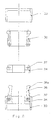
- the warp beam side coupling flange 2 is shown. You can see that stepped center bore 4, in which the clamping piece 6 is inserted according to Figure 1, and circumferential radial splines 3.
- the splines 3 can, as shown, be straight radial as well as obliquely radial.
- Figures 4 and 5 show a second embodiment of the coupling device, in which the Coupling can be done automatically.
- the bearing bell 12 ' is designed as a rotationally symmetrical part which is open on both sides, and again stored in warp beam warehouse 14.
- the bearing ring 15 comprises a base flange 21 in which one end of a pneumatic cylinder 22 is included. The other end of the pneumatic cylinder 22 is through a cylinder cover 24 closed. Cylinder cover 24, cylinder 22 and base flange 21 are by means of screws 14a firmly connected to the warp beam bearing 14.
- a hollow piston 26 is movably received, which is located on the Inner wall of the pneumatic cylinder 22 and, by means of a tubular extension 26a, on Supported inner circumference of the cylinder cover 24.
- a compressed air connection 23 and 25 is provided, so that the hollow piston 26 in both Directions 20 or 20 'can work.
- a piston 28 can be acted upon by pressure medium arranged, which carries a piston rod 29 extending in the axial direction 20.
- the Piston rod 29 runs within a connecting sleeve 31, which in turn on the hollow piston 26 is fastened and displaceable in the axial direction 20, 20 'within the bearing bell 12' is arranged.
- a piston rod 29 surrounding Spring assembly 32 arranged, which is on the one hand on an end-side annular surface 31a Connection sleeve 31 and on the other hand supported on the bottom 28a of the piston 28.
- the Claw carrier 34 comprises a plurality of radially arranged and extending in the axial direction 20 Claws 36 which are arranged pivotably about an axis 37 on the claw carrier 34.
- the claws 36 are pretensioned in their non-functional position by an annular spring 38.
- the Claws 36 are movable in the radial direction 40 to the outside and are slid on the at the free end of the piston rod 29 existing control edge 30 actuated.
- the free ends of the claws 36 each have a type of locking lug 36a, which is provided for this purpose is, the existing in the center hole 4 of the warp beam side coupling flange 2 Apply slope 5a of the circumferential step 5, the seat of the claws 36 by the Piston rod 29 is secured.
- the warp beam coupling is shown in the uncoupled state above the axis of rotation 12a according to FIG.
- the hollow piston 26 is in its rearmost position (arrow direction 20 '); pressure is present at the compressed air connection 23, while the compressed air connection 25 is depressurized.
- the piston 28 is in its foremost position (arrow direction 20) below the axis of rotation 12a; pressure is present at the connection 25, the piston rod 29 connected to the piston 28 being pressed forward against the force of the spring assembly 32 (arrow direction 20), so that the claws 36 are initially held in their non-functional position by the force of the spring 35.
- FIG. 5 shows the position of the claws 36 before they are positively connected to the coupling flange 2.
- the coupling flanges 2 and 8 lie against each other, the claws 36 still being radial innermost position (non-functional position).
- the pressure medium supply is deactivated, i.e. the piston 28 is relieved of pressure
- the Piston 28 and the piston rod 29 by the force of the spring assembly 32 in the direction of the arrow 20 ' pressed.
- the claws 36 slide along during the backward movement of the piston rod 29 whose control edge 30.
- the claws 36 are pressed in the direction of arrow 40 and start the stage 5 of the warp beam side coupling flange 2 a positive connection.
- the the positive position of the claws 36 is determined by that acting on the claws 36 Geometrically designed free end 29a of the piston rod 29 secured.
- the force curve in the individual parts is shown by the dashed line 41. Important is that no significant force acts on the claws 36, but only the free force outer end of the claws is used for power transmission. Possible low axial forces on the Claws 36 are received by the resilient mounting of the claw carrier 34.
- the lock is released and the warp beam is uncoupled from the weaving machine in reverse order to the order described above.
- the claws 36 are released from their seat by actuating the piston 28, which moves the piston rod 29 in the direction of arrow 20, so that the claws 36 the control edge 30 slide along and pivoted against the direction of arrow 40 by the force of the ring spring 38 become.
- the pneumatics are actuated, i.e. Compressed air on Compressed air connection 23 is applied so that the connecting sleeve 31 moves in the direction of the arrow 20 ' and thereby abuts an inner stop 13 of the bearing bell 12 ', see also FIG. 4.
- the bearing bell 12 ' is taken along in the direction of the arrow 20', so that the Coupling flange 8 detaches from the coupling flange 2 on the warp beam side.
- Figure 6 shows an illustration of the individual parts of the holding sleeve 33 with the arranged therein Claw carrier 34 with claws 36.
- the entire arrangement is in one of the annular surface 31b enclosed receptacle in the connecting sleeve 31 worn.
- the Retaining bush 33 is connected to the connecting bush 31 via a thread.
Landscapes
- Engineering & Computer Science (AREA)
- Textile Engineering (AREA)
- Looms (AREA)
- Warping, Beaming, Or Leasing (AREA)
- Processing Of Meat And Fish (AREA)
- Ultra Sonic Daignosis Equipment (AREA)
- Saccharide Compounds (AREA)
- Optical Communication System (AREA)
- Mechanical Coupling Of Light Guides (AREA)
- Rod-Shaped Construction Members (AREA)
- Two-Way Televisions, Distribution Of Moving Picture Or The Like (AREA)
Description
In bekannter Art besteht die Kettbaumkupplung z.B. aus einer an einem Ende des Kettbaumrohres angeflanschten Welle, welche ein Kettbaumzahnrad trägt, welches wiederum mit dem Antriebsritzel eines Antriebsmotors kämmt. Diese Art der Kupplung hat den Vorteil, daß eine hoch belastbare und spielfreie Kraftübertragung vom Antrieb auf das Kettbaumrohr erzielt wird. Nachteilig ist, daß beim Austausch des Kettbaumes die, meist durch Schrauben gesichert, Flanschverbindung zwischen Kettbaumrohr und Antriebswelle gelöst werden muß, was einen relativ hohen Zeitaufwand erfordert und ein fehlerhaftes Anziehen der Schrauben beim Wiederankuppeln nicht ausschließt.
Vorteil hierbei ist, daß zum Lösen der Verbindung meist nur eine Sicherungsschraube gelöst werden muß und die Kupplungswelle danach einfach aus der Aufnahme im Kettbaumrohr gezogen werden kann. Nachteile sind die eingeschränkte Belastbarkeit der Mehrkantwelle, sowie ein verhältnismäßig großes Spiel zwischen Welle und Wellenaufnahme, welches sich einerseits in Unregelmäßigkeiten der Webware niederschlägt und andererseits zu einem frühzeitigen Verschleiß der Kupplungsteile führt.
- Das Kuppeln und Verspannen erfolgt nach einem weitgehend vorgegebenen Ablauf manuell bzw. automatisch, so daß Bedienungsfehler, die ein unsauberes Kuppeln zur Folge haben, weitgehend vermieden werden können.
- Durch die stimverzahnten Kupplungsflansche ergibt sich eine spielfreie Verbindung zwischen Kettbaum und Kettbaumantrieb, wobei durch die Hirth-Verzahnung eine automatische Zentrierung, d.h. axiale Ausrichtung, des Kettbaumes gegenüber dem Kettbaumantrieb erfolgt. Die Stirnverzahnung ermöglicht ein sehr hohes zu übertragendes Drehmoment, welches beim Stand der Technik nur durch die bekannte, geschraubte Flanschverbindung erreicht wird.
- Nach dem Kuppeln und Verspannen wirken keine axialen Kräfte auf den Kettbaum. Die statischen Lager des Kettbaumes werden geschont.
- Figur 1:
- einen Halbschnitt durch eine erste Ausführungsform der Kettbaumkupplung, jeweils in nicht gekuppeltem und gekuppeltem Zustand;
- Figur 2:
- einen Schnitt durch den kettbaumseitigen Kupplungsflansch gemäß der Linie A-A in Figur 3;
- Figur 3:
- eine Draufsicht auf den kettbaumseitigen Kupplungsflansch;
- Figur 4:
- einen Halbschnitt durch eine weitere Ausführungsform der Kettbaumkupplung, jeweils in nicht gekuppeltem und gekuppeltem Zustand;
- Figur 5:
- einen Teilschnitt durch die Kettbaumkupplung im Bereich der Kupplungsflansche, vor dem Betätigen der Klauenverbindung;
- Figur 6:
- eine Darstellung der Einzelteile des in der Haltebüchse aufgenommenen Klauenträgers mit Klauen.
Unterhalb der Rotationsachse 12a befindet sich der Kolben 28 in seiner vordersten Stellung (Pfeilrichtung 20); am Anschluß 25 liegt Druck an, wobei die mit dem Kolben 28 verbundene Kolbenstange 29 entgegen der Kraft des Federpaketes 32 nach vorne (Pfeilrichtung 20) gedrückt wird, so daß die Klauen 36 zunächst durch die Kraft der Feder 35 in ihrer funktionslosen Stellung gehalten sind.
Figur 5 zeigt die Position der Klauen 36 bevor diese formschlüssig mit dem Kupplungsflansch 2 in Verbindung gebracht werden.
In der unteren Hälfte von Figur 4, also unterhalb der Rotationsachse 12a, wird die Spannkraft auf die Kolbenstange 29 zur Verriegelung der Klauen 36 allein durch das Federpaket 32 aufgebracht.
- 1
- Kettbaumrohr
- 1a
- Schraubbolzen
- 2
- Kupplungsflansch (kettbaumseitig)
- 3
- Hirth-Stirnverzahnung
- 4
- Mittelbohrung
- 5
- Stufe
- 5a
- Schräge
- 6
- Spannstück
- 6a
- Gewindebohrung
- 7
- Flanke
- 8
- Kupplungsflansch (kupplungsseitig)
- 9
- Hirth-Stirnverzahnung
- 10
- Anschlag
- 11
- Kettbaumzahnrad
- 12,12'
- Lagerglocke
- 12a
- Rotationsachse
- 12b
- Boden
- 13
- Anschlag
- 14
- Kettbaumlager
- 14a
- Schraube
- 15
- Lagerring
- 15a
- Lagerschale
- 16
- Lagerring
- 16a
- Lagerschale
- 17
- Spannschraube
- 18
- Führungsrohr
- 19
- Betätigungshebel
- 20,20'
- Pfeilrichtung
- 21
- Grundflansch
- 22
- Pneumatikzylinder
- 23
- Druckluftanschluß
- 24
- Zylinderdeckel
- 25
- Druckluftanschluß
- 26
- Hohlkolben
- 26a
- Ansatz
- 27
- Schnellkupplung
- 28
- Kolben
- 28a
- Boden
- 29
- Kolbenstange
- 29a
- Kolbenstangenende
- 30
- Steuerkante
- 31
- Verbindungsbüchse
- 31a
- Ringfläche
- 31b
- Ringfläche
- 32
- Federpaket
- 33
- Haltebüchse
- 34
- Klauenträger
- 35
- Feder
- 36
- Klaue
- 36a
- Rastnase
- 37
- Achse
- 38
- Ringfeder
- 39
- Dichtungspaket
- 40
- Pfeilrichtung
- 41
- Kraftverlauf
Claims (12)
- Kettbaumkupplung für Webmaschinen, mit einer durch einen Kettbaumantrieb rotierend angetriebenen und in einem Kettbaumlager (14) gelagerten Lagerglocke (12, 12'), welche einen Kupplungsflansch (8) aufweist, der mit einem am Kettbaumrohr eines Kettbaumes vorhandenen Kupplungsflansch (2) verbindbar ist, und Spannmittel (6,17; 29,32,33,34,36) zum Verspannen der miteinander in Eingriff befindlichen Kupplungsflansche (2; 8) aufnimmt, dadurch gekennzeichnet,daß die Kupplungsflansche (2; 8) jeweils mit einer Stirnverzahnung (3; 9) versehen sind,daß an der Lagerglocke (12; 12') Stellmittel (19; 22,26) vorgesehen sind, durch welche die Stimverzahnung (9) des Kupplungsflansches (8) der Lagerglocke in oder außer Eingriff mit der Stirnverzahnung (3) des Kupplungsflansches (2) des Kettbaumrohres (1) bringbar ist.
- Kettbaumkupplung nach Anspruch 1, dadurch gekennzeichnet, daß die Stirnverzahnungen (3; 9) auf einer umflaufenden Kreisfläche der Kupplungsflansche (2;8) radial nach außen weisend angeordnet sind.
- Kettbaumkupplung nach Anspruch 1 oder 2, dadurch gekennzeichnet, daß der kettbaumseitige Kupplungsflansch (2) eine gestuft ausgebildete Mittelbohrung (4) aufweist, wobei die Stufe (5) in Richtung der Stirnverzahnung (3) ausgebildet ist.
- Kettbaumkupplung nach einem der Ansprüche 1 bis 3, dadurch gekennzeichnet, daß das Stellmittel zum Verschieben der Lagerglocke (12) aus einem am Kettbaumlager (14) fest abgestützten und auf die Lagerglocke (12) wirkenden, manuell betätigbaren Hebel (19) besteht.
- Kettbaumkupplung nach einem der Ansprüche 1 bis 4, dadurch gekennzeichnet, daß die Spannmittel zum Verspannen der Kupplungsflansche (2;8) aus einer in einem Führungsrohr (18) innerhalb der Lagerglocke (12) aufgenommen Spannschraube (17) und aus einem im kettbaumseitigen Kupplungsflansch (2) sich abstützenden Spannstück (6) bestehen.
- Kettbaumkupplung nach einem der Ansprüche 1 bis 3, dadurch gekennzeichnet, daß die Stellmittel zum Verschieben des Kupplungsflansches (8) aus einer druckmittelbeaufschlagbaren Kolben-Zylindereinheit (22,26) bestehen.
- Kettbaumkupplung nach einem der Ansprüche 1 bis 3, dadurch gekennzeichnet, daß die Spannmittel zum Verspannen der Kupplungsflansche (2; 8) aus einer mit der druckmittelbeaufschlagbaren Kolben-Zylindereinheit (26,28) zusammenwirkenden Feder (32) und aus einer mehrere, radial schwenkbar gelagerte Klauen (36) tragenden Haltebüchse (33) bestehen und wobei die Klauen (36) mit der am Kupplungsflansch (2) vorhandenen umlaufenden Stufe (5) eine Verriegelung ausbilden.
- Kettbaumkupplung nach Anspruch 7, dadurch gekennzeichnet, daß die Klauen (36) um eine Achse (37) schwenkbar an einem Klauenträger (34) montiert sind, welcher unter Spannung einer Feder (35) in der Haltebüchse (33) aufgenommen ist.
- Kettbaumkupplung nach Anspruch 8, dadurch gekennzeichnet, daß die Klauen (36) mittels einer Ringfeder (38) in ihrer funktionslosen Stellung vorgespannt sind.
- Kettbaumkupplung nach einem der Ansprüche 7 bis 9, dadurch gekennzeichnet, daß die druckmittelbeaufschlagbare Kolben-Zylindereinheit (26,28) im als Hohlkolben (26) ausgebildeten Kolben integriert ist und zusammen mit diesem in axialer Richtung (20 bzw. 20') verschiebbar ist.
- Kettbaumkupplung nach einem der Ansprüche 7 bis 10, dadurch gekennzeichnet, daß der Kolben (28) eine Kolbenstange (29) betätigt, welche mittels eines Federpaketes (32) vorgespannt ist.
- Kettbaumkupplung nach einem der Ansprüche 1 bis 11, dadurch gekennzeichnet, daß die Kolbenstange (29) am vorderen, freien Ende (29a) eine Steuerkante (30) ausbildet, welche bei Verschieben der Kolbenstange in axialer Richtung (20') die radiale Schwenkbewegung der Klauen (36) aus der funktionslosen Stellung nach außen bewirkt.
Applications Claiming Priority (2)
| Application Number | Priority Date | Filing Date | Title |
|---|---|---|---|
| DE19724150 | 1997-06-07 | ||
| DE19724150A DE19724150C1 (de) | 1997-06-07 | 1997-06-07 | Kettbaumkupplung |
Publications (3)
| Publication Number | Publication Date |
|---|---|
| EP0882823A2 EP0882823A2 (de) | 1998-12-09 |
| EP0882823A3 EP0882823A3 (de) | 1999-12-01 |
| EP0882823B1 true EP0882823B1 (de) | 2002-07-31 |
Family
ID=7831850
Family Applications (1)
| Application Number | Title | Priority Date | Filing Date |
|---|---|---|---|
| EP98107342A Expired - Lifetime EP0882823B1 (de) | 1997-06-07 | 1998-04-22 | Kettbaumkupplung |
Country Status (7)
| Country | Link |
|---|---|
| US (1) | US6015034A (de) |
| EP (1) | EP0882823B1 (de) |
| JP (1) | JP2935840B2 (de) |
| AT (1) | ATE221587T1 (de) |
| DE (2) | DE19724150C1 (de) |
| ES (1) | ES2179398T3 (de) |
| PT (1) | PT882823E (de) |
Families Citing this family (5)
| Publication number | Priority date | Publication date | Assignee | Title |
|---|---|---|---|---|
| DE59803654D1 (de) * | 1998-12-01 | 2002-05-08 | Fischer & Krecke Gmbh & Co | Antriebskupplung für Druckzylinder |
| JP2000336553A (ja) * | 1999-05-31 | 2000-12-05 | Tsudakoma Corp | 送出ワープビームの連結装置 |
| DE102004054953B3 (de) * | 2004-02-04 | 2005-07-21 | Lindauer Dornier Gmbh | Vorrichtung zum Drehantrieb eines Kettbaumes |
| US20060083584A1 (en) * | 2004-10-18 | 2006-04-20 | Cooper Cameron Corporation | Replaceable hirth coupling component |
| DE102005019906B3 (de) * | 2005-04-29 | 2006-03-30 | Lindauer Dornier Gmbh | Webmaschine mit lösbarer Verbindung zwischen einem Antriebsmittel und dem Kettbaum einer Webmaschine |
Family Cites Families (11)
| Publication number | Priority date | Publication date | Assignee | Title |
|---|---|---|---|---|
| CH167773A (de) * | 1932-06-22 | 1934-03-15 | Camps Juan Picanol | Vorrichtung für die Schaltung des Warenbaumes von Webstühlen mit Klemmgesperre und Planetengetriebe. |
| US2140100A (en) * | 1936-08-10 | 1938-12-13 | Wagner Electric Corp | Clutch |
| US2405698A (en) * | 1942-09-24 | 1946-08-13 | Charles M Jameson | Dog clutch |
| US2639795A (en) * | 1950-08-25 | 1953-05-26 | Niagara Machine & Tool Works | Fluid operated clutch |
| US2806567A (en) * | 1954-01-15 | 1957-09-17 | Diamond Machine Tool Company | Air clutch |
| FR1232740A (fr) * | 1959-08-11 | 1960-10-11 | Webstuhlbau Karl Marx Stadt | Dispositif de support d'ensouples de chaîne et de tissu dans les métiers à tisser |
| DE2450748A1 (de) * | 1974-10-25 | 1976-04-29 | Hacoba Textilmaschinen | Spannfutter |
| DE3434113C1 (de) * | 1984-09-17 | 1986-06-05 | Benninger Ag, Uzwil | Wickelmaschine zum Aufwickeln und/oder Abwickeln von bahnförmig geführtem Gut |
| US4741226A (en) * | 1986-11-04 | 1988-05-03 | Darex Corporation | Power feed |
| BE1003988A3 (nl) * | 1990-04-13 | 1992-07-28 | Picanol Nv | Inrichting voor het aandrijven van een boom bij een weefmachine. |
| BE1008057A3 (nl) * | 1994-02-02 | 1996-01-03 | Picanol Nv | Inrichting voor het aan elkaar bevestigen van een element en een kettingboom bij weefmachines. |
-
1997
- 1997-06-07 DE DE19724150A patent/DE19724150C1/de not_active Expired - Fee Related
-
1998
- 1998-04-22 DE DE59804963T patent/DE59804963D1/de not_active Expired - Fee Related
- 1998-04-22 PT PT98107342T patent/PT882823E/pt unknown
- 1998-04-22 AT AT98107342T patent/ATE221587T1/de not_active IP Right Cessation
- 1998-04-22 EP EP98107342A patent/EP0882823B1/de not_active Expired - Lifetime
- 1998-04-22 ES ES98107342T patent/ES2179398T3/es not_active Expired - Lifetime
- 1998-05-26 US US09/084,058 patent/US6015034A/en not_active Expired - Fee Related
- 1998-06-08 JP JP10159552A patent/JP2935840B2/ja not_active Expired - Lifetime
Also Published As
| Publication number | Publication date |
|---|---|
| EP0882823A3 (de) | 1999-12-01 |
| ATE221587T1 (de) | 2002-08-15 |
| US6015034A (en) | 2000-01-18 |
| DE19724150C1 (de) | 1998-11-19 |
| DE59804963D1 (de) | 2002-09-05 |
| JPH1112873A (ja) | 1999-01-19 |
| EP0882823A2 (de) | 1998-12-09 |
| ES2179398T3 (es) | 2003-01-16 |
| JP2935840B2 (ja) | 1999-08-16 |
| PT882823E (pt) | 2002-11-29 |
Similar Documents
| Publication | Publication Date | Title |
|---|---|---|
| EP0017748B1 (de) | Nachspannendes Bohrfutter | |
| DE3509635C1 (de) | Werkzeughalteeinrichtung fuer Drehmaschinen | |
| DE2757739C3 (de) | Bei Drehzahlgleichheit selbsttätig einrückbare Zahnkupplung | |
| EP0582804B1 (de) | Schalteinrichtung für ein Getriebe | |
| DE102004052869B4 (de) | Parkbremsmechanismus für ein integriertes Schalt- und Verteilergetriebe | |
| EP0245629B1 (de) | Spanneinrichtung an Drehspindeln von Drehmaschinen für kraftbetätigte Werkstückhalter, insbesondere Spannfutter | |
| DE1103723B (de) | Einrichtung zum Spannen und Loesen von Werkzeugen | |
| DE3813670A1 (de) | Kupplung zwischen zwei maschinenteilen | |
| DE4423932A1 (de) | Vorrichtung zum Schnellwechseln eines Spannzeugs einer Werkzeugmaschine | |
| EP0882823B1 (de) | Kettbaumkupplung | |
| DE3245720C2 (de) | Antriebsanordnung für einen Dreh-, Schwenk- und Fahrantrieb eines Fahrzeugs, insbesondere für einen Bagger | |
| DE2754357C2 (de) | ||
| DE2361019C2 (de) | Lösbare starre Kupplung | |
| DE19854570C1 (de) | Kupplung | |
| DE2316605C2 (de) | Vorrichtung zum Spannen und Lösen von einen konischen Schaft aufweisenden, in eine Spindelaufnahme einsetzbaren Werkzeugen | |
| DE2721558C2 (de) | Schnell lösbare Kupplung zweier Kupplungsflansche | |
| DE2521315B2 (de) | Hydraulische Überlastkupplung, insbesondere für Förderer- und Hobelantriebe u.dgl | |
| DE2801618C3 (de) | Gelenksperre | |
| EP0292022A2 (de) | Betätigungsvorrichtung | |
| DE4405155A1 (de) | Sicherheits-Kupplungsvorrichtung | |
| DE3219295C2 (de) | Spannfutter für Drehmaschinen | |
| EP3643436A1 (de) | Spannfutter für werkzeugmaschinen | |
| DE3825711A1 (de) | Drehwerkzeug | |
| AT406288B (de) | Antriebskopf für die aufnahme und führung eines einsteckwerkzeuges | |
| EP1153709A2 (de) | Zusatzwerkzeug für eine Fräsmaschine |
Legal Events
| Date | Code | Title | Description |
|---|---|---|---|
| PUAI | Public reference made under article 153(3) epc to a published international application that has entered the european phase |
Free format text: ORIGINAL CODE: 0009012 |
|
| AK | Designated contracting states |
Kind code of ref document: A2 Designated state(s): AT BE CH DE ES FR GB IT LI PT |
|
| AX | Request for extension of the european patent |
Free format text: AL;LT;LV;MK;RO;SI |
|
| PUAL | Search report despatched |
Free format text: ORIGINAL CODE: 0009013 |
|
| AK | Designated contracting states |
Kind code of ref document: A3 Designated state(s): AT BE CH CY DE DK ES FI FR GB GR IE IT LI LU MC NL PT SE |
|
| AX | Request for extension of the european patent |
Free format text: AL;LT;LV;MK;RO;SI |
|
| 17P | Request for examination filed |
Effective date: 20000131 |
|
| AKX | Designation fees paid |
Free format text: AT BE CH DE ES FR GB IT LI PT |
|
| GRAG | Despatch of communication of intention to grant |
Free format text: ORIGINAL CODE: EPIDOS AGRA |
|
| GRAG | Despatch of communication of intention to grant |
Free format text: ORIGINAL CODE: EPIDOS AGRA |
|
| GRAH | Despatch of communication of intention to grant a patent |
Free format text: ORIGINAL CODE: EPIDOS IGRA |
|
| 17Q | First examination report despatched |
Effective date: 20011206 |
|
| GRAH | Despatch of communication of intention to grant a patent |
Free format text: ORIGINAL CODE: EPIDOS IGRA |
|
| GRAA | (expected) grant |
Free format text: ORIGINAL CODE: 0009210 |
|
| AK | Designated contracting states |
Kind code of ref document: B1 Designated state(s): AT BE CH DE ES FR GB IT LI PT |
|
| REF | Corresponds to: |
Ref document number: 221587 Country of ref document: AT Date of ref document: 20020815 Kind code of ref document: T |
|
| REG | Reference to a national code |
Ref country code: GB Ref legal event code: FG4D Free format text: NOT ENGLISH Ref country code: CH Ref legal event code: EP |
|
| REF | Corresponds to: |
Ref document number: 59804963 Country of ref document: DE Date of ref document: 20020905 |
|
| REG | Reference to a national code |
Ref country code: CH Ref legal event code: NV Representative=s name: R. A. EGLI & CO. PATENTANWAELTE |
|
| REG | Reference to a national code |
Ref country code: PT Ref legal event code: SC4A Free format text: AVAILABILITY OF NATIONAL TRANSLATION Effective date: 20021004 |
|
| GBT | Gb: translation of ep patent filed (gb section 77(6)(a)/1977) |
Effective date: 20021119 |
|
| ET | Fr: translation filed | ||
| REG | Reference to a national code |
Ref country code: ES Ref legal event code: FG2A Ref document number: 2179398 Country of ref document: ES Kind code of ref document: T3 |
|
| PG25 | Lapsed in a contracting state [announced via postgrant information from national office to epo] |
Ref country code: GB Free format text: LAPSE BECAUSE OF NON-PAYMENT OF DUE FEES Effective date: 20030422 Ref country code: AT Free format text: LAPSE BECAUSE OF NON-PAYMENT OF DUE FEES Effective date: 20030422 |
|
| PG25 | Lapsed in a contracting state [announced via postgrant information from national office to epo] |
Ref country code: ES Free format text: LAPSE BECAUSE OF NON-PAYMENT OF DUE FEES Effective date: 20030423 |
|
| PG25 | Lapsed in a contracting state [announced via postgrant information from national office to epo] |
Ref country code: LI Free format text: LAPSE BECAUSE OF NON-PAYMENT OF DUE FEES Effective date: 20030430 Ref country code: CH Free format text: LAPSE BECAUSE OF NON-PAYMENT OF DUE FEES Effective date: 20030430 Ref country code: BE Free format text: LAPSE BECAUSE OF NON-PAYMENT OF DUE FEES Effective date: 20030430 |
|
| PLBE | No opposition filed within time limit |
Free format text: ORIGINAL CODE: 0009261 |
|
| STAA | Information on the status of an ep patent application or granted ep patent |
Free format text: STATUS: NO OPPOSITION FILED WITHIN TIME LIMIT |
|
| 26N | No opposition filed |
Effective date: 20030506 |
|
| BERE | Be: lapsed |
Owner name: *LINDAUER DORNIER G.M.B.H. Effective date: 20030430 |
|
| PG25 | Lapsed in a contracting state [announced via postgrant information from national office to epo] |
Ref country code: PT Free format text: LAPSE BECAUSE OF NON-PAYMENT OF DUE FEES Effective date: 20031031 |
|
| PG25 | Lapsed in a contracting state [announced via postgrant information from national office to epo] |
Ref country code: DE Free format text: LAPSE BECAUSE OF NON-PAYMENT OF DUE FEES Effective date: 20031101 |
|
| GBPC | Gb: european patent ceased through non-payment of renewal fee |
Effective date: 20030422 |
|
| REG | Reference to a national code |
Ref country code: CH Ref legal event code: PL |
|
| PG25 | Lapsed in a contracting state [announced via postgrant information from national office to epo] |
Ref country code: FR Free format text: LAPSE BECAUSE OF NON-PAYMENT OF DUE FEES Effective date: 20031231 |
|
| REG | Reference to a national code |
Ref country code: FR Ref legal event code: ST Ref country code: PT Ref legal event code: MM4A Free format text: LAPSE DUE TO NON-PAYMENT OF FEES Effective date: 20031031 |
|
| REG | Reference to a national code |
Ref country code: ES Ref legal event code: FD2A Effective date: 20030423 |
|
| PG25 | Lapsed in a contracting state [announced via postgrant information from national office to epo] |
Ref country code: IT Free format text: LAPSE BECAUSE OF NON-PAYMENT OF DUE FEES Effective date: 20050422 |