EP0882910A2 - Transmission continue de vitesse du type torique - Google Patents
Transmission continue de vitesse du type torique Download PDFInfo
- Publication number
- EP0882910A2 EP0882910A2 EP98304449A EP98304449A EP0882910A2 EP 0882910 A2 EP0882910 A2 EP 0882910A2 EP 98304449 A EP98304449 A EP 98304449A EP 98304449 A EP98304449 A EP 98304449A EP 0882910 A2 EP0882910 A2 EP 0882910A2
- Authority
- EP
- European Patent Office
- Prior art keywords
- boss portion
- trunnion
- continuously variable
- variable transmission
- trunnions
- Prior art date
- Legal status (The legal status is an assumption and is not a legal conclusion. Google has not performed a legal analysis and makes no representation as to the accuracy of the status listed.)
- Granted
Links
Images


Classifications
-
- F—MECHANICAL ENGINEERING; LIGHTING; HEATING; WEAPONS; BLASTING
- F16—ENGINEERING ELEMENTS AND UNITS; GENERAL MEASURES FOR PRODUCING AND MAINTAINING EFFECTIVE FUNCTIONING OF MACHINES OR INSTALLATIONS; THERMAL INSULATION IN GENERAL
- F16H—GEARING
- F16H15/00—Gearings for conveying rotary motion with variable gear ratio, or for reversing rotary motion, by friction between rotary members
- F16H15/02—Gearings for conveying rotary motion with variable gear ratio, or for reversing rotary motion, by friction between rotary members without members having orbital motion
- F16H15/04—Gearings providing a continuous range of gear ratios
- F16H15/06—Gearings providing a continuous range of gear ratios in which a member A of uniform effective diameter mounted on a shaft may co-operate with different parts of a member B
- F16H15/32—Gearings providing a continuous range of gear ratios in which a member A of uniform effective diameter mounted on a shaft may co-operate with different parts of a member B in which the member B has a curved friction surface formed as a surface of a body of revolution generated by a curve which is neither a circular arc centered on its axis of revolution nor a straight line
- F16H15/36—Gearings providing a continuous range of gear ratios in which a member A of uniform effective diameter mounted on a shaft may co-operate with different parts of a member B in which the member B has a curved friction surface formed as a surface of a body of revolution generated by a curve which is neither a circular arc centered on its axis of revolution nor a straight line with concave friction surface, e.g. a hollow toroid surface
- F16H15/38—Gearings providing a continuous range of gear ratios in which a member A of uniform effective diameter mounted on a shaft may co-operate with different parts of a member B in which the member B has a curved friction surface formed as a surface of a body of revolution generated by a curve which is neither a circular arc centered on its axis of revolution nor a straight line with concave friction surface, e.g. a hollow toroid surface with two members B having hollow toroid surfaces opposite to each other, the member or members A being adjustably mounted between the surfaces
-
- F—MECHANICAL ENGINEERING; LIGHTING; HEATING; WEAPONS; BLASTING
- F16—ENGINEERING ELEMENTS AND UNITS; GENERAL MEASURES FOR PRODUCING AND MAINTAINING EFFECTIVE FUNCTIONING OF MACHINES OR INSTALLATIONS; THERMAL INSULATION IN GENERAL
- F16H—GEARING
- F16H15/00—Gearings for conveying rotary motion with variable gear ratio, or for reversing rotary motion, by friction between rotary members
- F16H15/02—Gearings for conveying rotary motion with variable gear ratio, or for reversing rotary motion, by friction between rotary members without members having orbital motion
- F16H15/04—Gearings providing a continuous range of gear ratios
- F16H15/06—Gearings providing a continuous range of gear ratios in which a member A of uniform effective diameter mounted on a shaft may co-operate with different parts of a member B
- F16H15/16—Gearings providing a continuous range of gear ratios in which a member A of uniform effective diameter mounted on a shaft may co-operate with different parts of a member B in which the member B has a conical friction surface
Definitions
- the present invention relates in general to a toroidal type continuously variable transmission, and more particularly to a toroidal power transmission unit employed in the transmission.
- toroidal type continuously variable transmission will be referred to as toroidal type CVT, hereinafter.
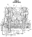
- Figs. 9 and 10 show part of the toroidal type CVT.
- designated by numerals 1 and 2 are input and output cone discs which are arranged on a common rotation axis O 1
- numerals 3 and 3 are power rollers which are each operatively interposed between the input and output cone discs 1 and 2.
- the power rollers 3 and 3 are arranged to face each other with the axis O 1 placed therebetween.
- the input and output cone discs 1 and 2 and the two power rollers 3 and 3 constitute one toroidal power-transmission unit.
- a double cavity toroidal type CVT two (that is, front and rear) toroidal power-transmission units are employed, which are coaxially arranged on the axis O 1 with their output cone discs 2 and 2 connected in a back-to-back connecting manner.
- the power rollers 3 and 3 of the front transmission unit are rotatably supported by respective trunnions 4 and 4 as is seen from Fig. 9, and the power rollers of the rear transmission unit are rotatably supported by respective trunnions 5 and 5 as will be understood from Fig. 10.
- each trunnion 4 (or 5) can pivot between a neutral position as shown in Fig. 9 wherein a rotation axis O 2 of the power roller 3 intersects the rotation axis O 1 of the input and output cone discs 1 and 2 and an offset position wherein the trunnion 4 (or 5) is inclined toward a pivot axis O 3 of the power roller 3 which intersects the rotation axis O 2 at right angles.
- the trunnion 4 (or 5) pivots about the pivot axis O 3 .
- each trunnion 4 (or 5) has a shaft 10 connected thereto through a connecting pin 12, the shaft 10 extending in the direction of the pivot axis O 3 .
- a piston 14 is connected to the shaft 10.
- the piston 14 is formed with a hollow boss portion 14a which receives therein the shaft 10. Due to movement of the piston 14 along an axis of the hollow boss portion 14a, the above-mentioned pivotal movement of the trunnion 4 (or 5) is induced.
- the hollow boss portion 14a of the piston 14 of the front transmission unit passes through both a cylinder body 15 which houses therein the piston 14 and a control valve body 18 which produces a hydraulic pressure for actuating the piston 14, and the hollow boss portion 14a of the piston, which is incorporated with the right trunnion 4, passes through only the cylinder body 15.
- the hollow boss portions 14a of the pistons 14 of the rear transmission unit, which are incorporated with the trunnions 5 pass through the cylinder body 15.
- the control valve body 18 is equipped with a speed control valve 17. That is, upon receiving a gear ratio command, the speed control valve 17 moves the pistons 14 with a hydraulic pressure corresponding to the content of the command. With this, each piston 14 pivots through the corresponding shaft 10 the trunnion 4 (or 5) between the above-mentioned neutral position of Fig. 9 and the above-mentioned offset position. Upon this, each power roller 3 is pivoted about the pivot axis O 3 while receiving a component force from the input and output cone discs 1 and 2, so that the rotation speed of the output cone disc 2 is continuously varied relative to that of the input cone disc 1. That is, due to continuously varying contact points of the power rollers 3 to the input and output cone discs 1 and 2, the gear ratio is continuously varied between the input and output cone discs 1 and 2. In other words, a continuously variable speed change is obtained.
- the shaft 10 of one of the trunnions 4 of the front transmission unit has a lower end projected downward from the control valve body 18, to which a precess cam 9 is secured.
- a speed change link 21 is incorporated with the precess cam 9, through which the above-mentioned movement of the trunnion 4 is fed back to the speed control valve 17. Due to this feed back control, the trunnions 4 and 5 of the front and rear transmission units are forced to return toward their original position, and when the existing gear ratio becomes in agreement with the target value of the command, the trunnions 4 and 5 are returned to the original positions bringing back the power rollers 3 to their neutral positions. With this, the gear ratio is kept at the target value.
- each power roller 3 under operation of the toroidal power transmission unit, each power roller 3 is hardly compressed between the input and output cone discs 1 and 2 with a force corresponding to a delivered torque therebetween because the torque delivery has to be made by shearing oil film placed between the power roller 3 and each of the input and output cone discs 1 and 2. Accordingly, as is understood from Fig. 11, under operation, each power roller 3 is applied with a marked thrust F in a direction to be driven out from the input and output cone discs 1 and 2.
- the upper ends and lower ends of the paired trunnions 4 and 4 (or 5 and 5) are connected through the respective upper and lower links 6 and 7, as is described hereinabove.
- the trunnion 4 (or 5) is resiliently flexed or bent slightly but in a certain degree with the upper and lower links 6 and 7 serving as fulcrums, so that the shaft 10 and the piston 14 are forced to incline, as shown.
- this inclination tends to generate a marked friction force between the hollow boss portion 14a of the piston 14 and a wall of a bore the cylinder body 15 through which the boss portion 14a passes.
- elimination of such friction force is needed.
- a toroidal type CVT in which an inevitably occurring resilient flex or bending of the trunnion caused by the above-mentioned thrust F is suitably absorbed or damped by an articulated structure arranged between the trunnion and the piston, so that the flex has no effect on the piston.
- a friction roller type continuously variable transmission which comprises input and output discs arranged on a common axis; friction rollers each being operatively interposed between the input and output discs to transmit rotation therebetween; supporting members, each supporting member rotatably supporting the friction roller and having a shaft extending therefrom; pistons, each including a hollow boss portion in which the shaft of the corresponding supporting member is received, the hollow boss portion having a first end engageable with a second end of the corresponding supporting member, so that when the piston is axially moved, the corresponding friction roller pivots to continuously change a speed ratio between the input and output discs; links each connecting corresponding ends of the supporting members to suppress displacement of the friction roller which would occur when the friction roller is applied with a certain thrust from the input and output discs; and articulated structures associated with the supporting members respectively, each articulated structure being arranged between the first and second ends to permit a pivotal movement of the supporting member relative to the corresponding hollow boss portion when the friction roller is applied with the certain thrust.
- a toroidal type CVT 100A which is a first embodiment of the present invention.
- the transmission 100A of this embodiment is of the double cavity type which comprises front and rear toroidal power transmission units which are coaxially arranged in a transmission case.
- these two power transmission units will be referred to as front and rear transmission units respectively hereinafter.
- the front transmission unit (viz., front toroidal power transmission unit) comprises two trunnions 4 which rotatably hold respective power rollers which are each put between input and output cone discs.
- the trunnion 4 has a lower end from which the shaft 10 (illustrated in a left side of the drawing) extends downward. That is, the shaft 10 has an upper end connected through a connecting pin 12 to the lower end of the trunnion 4.
- the shaft 10 passes through a washer 31, a hollow boss portion 14a of a piston 14, and a precess cam 9.
- a threaded lower end of the shaft 10 has a nut 32 engaged thereto for holding the parts 31, 14a, and 9 in position. Due to a certain thrust produced by the nut 32, the washer 31 is tightly pressed against the lower end surface of the trunnion 4.
- the lower end of the trunnion 4 has a wire pulley 34 immovably connected thereto.
- the wire pulley 34 puts thereon a looped wire 33 which extends to another wire pulley (34) which is incorporated with a trunnion 5 employed in the rear transmission unit (viz., rear toroidal power transmission unit). That is, due to usage of the two wire pulleys 34 and the looped wire 33 extending, synchronous movement is achieved between the power rollers in the front transmission unit and those in the rear transmission unit.
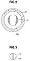
- the wire pulley 34 has a non-circular center opening 34a with which the lower end of the trunnion 4 is snugly engaged, so that the wire pulley 34 is suppressed from rotation relative to the trunnion 4. Due to usage of the washer 31, the wire pulley 34 is held in position. As is shown, an upper face 31a of the washer 31, which is shown by the area illustrated with dots, has a larger area for evenly contacting the wire pulley 34.
- a lower surface 31b of the washer 31 is shaped concave and an upper end 14b of the hollow boss portion 14a of the piston 14, which contacts the concave lower surface 31b of the washer 31, is shaped convex. More specifically, the concave lower surface 31b of the washer 31 and the convex surface of the upper end 14b of the hollow boss portion 14a are each shaped to constitute part of an imaginary cylindrical wall whose center axis (not shown) extends in parallel with an axis of the connecting pin 12, that is, in a direction perpendicular to the surface of Fig. 1.
- a radius of curvature of the convex upper end 14b may be smaller than that of the concave lower surface 31b. In this case, undesired "gall" phenomenon between the two contacting portions 14b and 31b is assuredly eliminated.
- the lower surface 31b of the washer 31 and the upper end surface 14b of the hollow boss portion 14a may be shaped convex and concave respectively.
- the shaft 10 has a thinner middle portion 10a which is placed in the hollow boss portion 14a of the piston 14.
- the thinner middle portion 10a is so constructed and oriented as to be resiliently flexed when applied with the above-mentioned thrust.
- the thickness of the thinner middle portion 10a measured in a direction perpendicular to the axis of the connecting pin 12 is the smallest and the thickness of the thinner middle portion 10a measured in a direction parallel with the axis of the connecting pin 12 is the largest.
- the shaft 10 has the thinner middle portion 10a between the upper end connected to the trunnion 4 and the lower end intimately engaged with the hollow of the boss portion 14a of the piston 14.
- the shaft 10 has a lower flexural rigidity against a thrust applied thereto in the direction perpendicular to the axis of the connecting pin 12. In other words, when a certain thrust is applied thereto from the trunnion 4, resilient flex of the shaft 10 takes place easily.
- a lower end of the hollow boss portion 14a of the piston 14 is projected from a bore of the cylinder body 15.
- the projected lower end of the portion 14a has an aluminum collar 35 disposed thereon.
- An upper half of the collar 35 is received in the bore of the cylinder body 15, as shown. Due to provision of the aluminum collar 35, an inner wall of the cylinder body 15 made of aluminum is protected from contacting the hollow boss portion 14a of the piston 14 made of iron.
- the above-mentioned articulated structure is also applied to the other trunnion 4 installed in the front transmission unit.
- the shaft 10 extending from the other trunnion 4 has also a thinner middle portion corresponding to the above-mentioned thinner middle portion 10a.
- the control valve body 18 installs therein a speed control valve 17. That is, upon receiving a gear ratio command, the speed control valve 17 moves the pistons 14 with a hydraulic pressure corresponding to the content of the command. With this, each piston 14 pivots through the corresponding shaft 10 the trunnion 4 (or 5) between the above-mentioned neutral position and a desired offset position. Upon this, each power roller 3 is pivoted about the pivot axis O 3 (see Fig. 9) while receiving a component force from the input and output cone discs, so that the rotation speed of the output cone disc is continuously varied. Thus, a continuously variable speed change is carried out.
- the precess cam 9 installed in the front transmission unit feeds back the movement of the corresponding trunnion 4 to the speed control valve 17.
- the trunnions 4 and 5 of the front and rear transmission units are forced to return toward their original positions, and when the existing gear ratio becomes in agreement with the target value of the command, the trunnions 4 and 5 are returned to the original positions bringing back the power rollers 3 to their neutral positions. With this, the gear ratio is kept at the target value.
- a so-called "articulated structure" is associated with each of the trunnions 4 and 5 in the above-mentioned manner, and the shaft 10 extending from each of the trunnions 4 and 5 has a thinner middle portion 10a which is constructed in the above-mentioned manner.
- the wire pulley 31 can be tightly secured to the lower end of the trunnion 4 (or 5). This increases the durability of the wire pulley 34.
- a toroidal type CVT 100B which is a second embodiment of the present invention. Since this second embodiment 100B is similar to the above-mentioned first embodiment 100A, only parts and portions which are different from those of the first embodiment 100A will be described in the following.
- the second embodiment 100B there is no member which corresponds to the washer 31 employed in the first embodiment 100A. That is, in the second embodiment 100B, an upper end of a hollow boss portion 14a of a piston 14 directly and slidably contacts a lower end surface of the trunnion 4 or 5.
- the lower end surface 4a or 5a of the trunnion 4 or 5 is shaped concave, and the upper end 14b of the hollow boss portion 14a is shaped convex. More specifically, the concave lower end surface 4a or 4b of the trunnion 4 or 5 and the convex upper end 14b of the hollow boss portion 14a are each shaped to constitute part of an imaginary cylindrical wall.
- a radius of curvature of the convex upper end 14b maybe smaller than that of the concave lower end surface 4a or 4b. In this case, undesired "gall" phenomenon between the two contacting portions 14b and 4a (or 4b) is assuredly eliminated.
- this second embodiment 100B the above-mentioned first and second advantages possessed by the first embodiment 100A are obtained. Furthermore, in the second embodiment 100B, a simpler and lower cost production is achieved due to non-use of a washer.
Landscapes
- Engineering & Computer Science (AREA)
- General Engineering & Computer Science (AREA)
- Mechanical Engineering (AREA)
- Friction Gearing (AREA)
Applications Claiming Priority (3)
| Application Number | Priority Date | Filing Date | Title |
|---|---|---|---|
| JP14735497 | 1997-06-05 | ||
| JP14735497A JP3237573B2 (ja) | 1997-06-05 | 1997-06-05 | 摩擦車式無段変速機 |
| JP147354/97 | 1997-06-05 |
Publications (3)
| Publication Number | Publication Date |
|---|---|
| EP0882910A2 true EP0882910A2 (fr) | 1998-12-09 |
| EP0882910A3 EP0882910A3 (fr) | 1999-02-03 |
| EP0882910B1 EP0882910B1 (fr) | 2002-02-20 |
Family
ID=15428303
Family Applications (1)
| Application Number | Title | Priority Date | Filing Date |
|---|---|---|---|
| EP98304449A Expired - Lifetime EP0882910B1 (fr) | 1997-06-05 | 1998-06-05 | Transmission continue de vitesse du type torique |
Country Status (5)
| Country | Link |
|---|---|
| US (1) | US6030309A (fr) |
| EP (1) | EP0882910B1 (fr) |
| JP (1) | JP3237573B2 (fr) |
| KR (1) | KR100285078B1 (fr) |
| DE (1) | DE69803901T2 (fr) |
Cited By (7)
| Publication number | Priority date | Publication date | Assignee | Title |
|---|---|---|---|---|
| EP0933559A3 (fr) * | 1998-01-29 | 1999-10-06 | Nissan Motor Company, Limited | Variateur continu de vitesse à rouleaux de traction |
| EP0980992A1 (fr) * | 1998-08-11 | 2000-02-23 | Nissan Motor Co., Ltd. | Tourillon pour une transmission continue de vitesse du type torique ainsi qu'un procédé de fabrication d'un tel tourillon |
| DE19927268C2 (de) * | 1998-06-19 | 2002-01-24 | Nissan Motor | Stufenlos verstellbares Toroidgetriebe |
| WO2002006702A1 (fr) * | 2000-07-15 | 2002-01-24 | Zf Friedrichshafen Ag | Boite de vitesses a friction a transmission continue |
| WO2002044587A1 (fr) * | 2000-11-29 | 2002-06-06 | Torotrak (Development) Limited | Mecanisme de commande de galet |
| EP1245871A3 (fr) * | 2001-03-27 | 2004-01-14 | Nissan Motor Company, Limited | Commande de rapport d'une transmission toroidale de traction avec un actuateur à course morte par came |
| EP1275881A3 (fr) * | 2001-07-05 | 2009-06-17 | Nissan Motor Company, Limited | Transmission toroidale à variation continue |
Families Citing this family (7)
| Publication number | Priority date | Publication date | Assignee | Title |
|---|---|---|---|---|
| JP3237573B2 (ja) | 1997-06-05 | 2001-12-10 | 日産自動車株式会社 | 摩擦車式無段変速機 |
| DE19822194B4 (de) * | 1998-05-16 | 2008-02-21 | Zf Friedrichshafen Ag | Stufenloses Reibradgetriebe |
| JP3506230B2 (ja) * | 2000-04-03 | 2004-03-15 | 日産自動車株式会社 | トロイダル型無段変速機 |
| JP2002106667A (ja) | 2000-10-04 | 2002-04-10 | Honda Motor Co Ltd | トロイダル型無段変速機 |
| JP3790191B2 (ja) | 2002-07-18 | 2006-06-28 | ジヤトコ株式会社 | トロイダル型無段変速機 |
| JP3790193B2 (ja) | 2002-07-26 | 2006-06-28 | ジヤトコ株式会社 | トロイダル型無段変速機 |
| JP4962350B2 (ja) * | 2008-02-27 | 2012-06-27 | 日本精工株式会社 | トロイダル型無段変速機 |
Citations (2)
| Publication number | Priority date | Publication date | Assignee | Title |
|---|---|---|---|---|
| JPS6392859U (fr) | 1986-12-09 | 1988-06-15 | ||
| JPH09147354A (ja) | 1995-11-20 | 1997-06-06 | Victor Co Of Japan Ltd | 磁気テープ |
Family Cites Families (8)
| Publication number | Priority date | Publication date | Assignee | Title |
|---|---|---|---|---|
| JPS62202564A (ja) * | 1986-03-03 | 1987-09-07 | Agency Of Ind Science & Technol | ヘテロ接合電界効果トランジスタ |
| JPH0516444Y2 (fr) * | 1986-06-13 | 1993-04-30 | ||
| JPS6392859A (ja) * | 1986-10-08 | 1988-04-23 | Honda Motor Co Ltd | 後進機構付き変速装置 |
| JPS63130954A (ja) * | 1986-11-20 | 1988-06-03 | Nissan Motor Co Ltd | 摩擦車式無段変速機構 |
| US5423727A (en) * | 1988-11-21 | 1995-06-13 | Torotrak (Development) Limited | Transmission of the toroidal-race rolling-traction type |
| JP2689758B2 (ja) * | 1991-04-04 | 1997-12-10 | 日産自動車株式会社 | 摩擦車式無段変速機 |
| JP3237503B2 (ja) * | 1996-02-19 | 2001-12-10 | 日産自動車株式会社 | 摩擦車式無段変速機 |
| JP3237573B2 (ja) | 1997-06-05 | 2001-12-10 | 日産自動車株式会社 | 摩擦車式無段変速機 |
-
1997
- 1997-06-05 JP JP14735497A patent/JP3237573B2/ja not_active Expired - Fee Related
-
1998
- 1998-06-03 KR KR1019980020624A patent/KR100285078B1/ko not_active Expired - Fee Related
- 1998-06-04 US US09/090,183 patent/US6030309A/en not_active Expired - Lifetime
- 1998-06-05 EP EP98304449A patent/EP0882910B1/fr not_active Expired - Lifetime
- 1998-06-05 DE DE69803901T patent/DE69803901T2/de not_active Expired - Lifetime
Patent Citations (2)
| Publication number | Priority date | Publication date | Assignee | Title |
|---|---|---|---|---|
| JPS6392859U (fr) | 1986-12-09 | 1988-06-15 | ||
| JPH09147354A (ja) | 1995-11-20 | 1997-06-06 | Victor Co Of Japan Ltd | 磁気テープ |
Cited By (12)
| Publication number | Priority date | Publication date | Assignee | Title |
|---|---|---|---|---|
| EP0933559A3 (fr) * | 1998-01-29 | 1999-10-06 | Nissan Motor Company, Limited | Variateur continu de vitesse à rouleaux de traction |
| US6152849A (en) * | 1998-01-29 | 2000-11-28 | Nissan Motor Co., Ltd. | Friction roller type continuously variable transmission |
| DE19927268C2 (de) * | 1998-06-19 | 2002-01-24 | Nissan Motor | Stufenlos verstellbares Toroidgetriebe |
| EP0980992A1 (fr) * | 1998-08-11 | 2000-02-23 | Nissan Motor Co., Ltd. | Tourillon pour une transmission continue de vitesse du type torique ainsi qu'un procédé de fabrication d'un tel tourillon |
| US6224508B1 (en) | 1998-08-11 | 2001-05-01 | Nissan Motor Co., Ltd. | Trunnion of a toroidal continuously variable transmission and manufacturing process thereof |
| WO2002006702A1 (fr) * | 2000-07-15 | 2002-01-24 | Zf Friedrichshafen Ag | Boite de vitesses a friction a transmission continue |
| DE10034454A1 (de) * | 2000-07-15 | 2002-01-24 | Zahnradfabrik Friedrichshafen | Stufenloses Reibradgetriebe |
| US6908409B2 (en) | 2000-07-15 | 2005-06-21 | Zf Friedrichshafen Ag | Stepless friction drive |
| WO2002044587A1 (fr) * | 2000-11-29 | 2002-06-06 | Torotrak (Development) Limited | Mecanisme de commande de galet |
| US7018320B2 (en) | 2000-11-29 | 2006-03-28 | Torotrak (Development) Limited | Roller control unit |
| EP1245871A3 (fr) * | 2001-03-27 | 2004-01-14 | Nissan Motor Company, Limited | Commande de rapport d'une transmission toroidale de traction avec un actuateur à course morte par came |
| EP1275881A3 (fr) * | 2001-07-05 | 2009-06-17 | Nissan Motor Company, Limited | Transmission toroidale à variation continue |
Also Published As
| Publication number | Publication date |
|---|---|
| DE69803901T2 (de) | 2002-09-12 |
| US6030309A (en) | 2000-02-29 |
| EP0882910A3 (fr) | 1999-02-03 |
| KR100285078B1 (ko) | 2001-04-02 |
| EP0882910B1 (fr) | 2002-02-20 |
| JP3237573B2 (ja) | 2001-12-10 |
| JPH10331938A (ja) | 1998-12-15 |
| DE69803901D1 (de) | 2002-03-28 |
| KR19990006656A (ko) | 1999-01-25 |
Similar Documents
| Publication | Publication Date | Title |
|---|---|---|
| EP0967413B1 (fr) | Transmission continue de vitesse du type torique | |
| EP0882910B1 (fr) | Transmission continue de vitesse du type torique | |
| JP2000314458A (ja) | 伝動装置 | |
| KR100240617B1 (ko) | 무단 트랙션 롤러 변속기의 시프트 제어 유니트 | |
| US4386536A (en) | Infinitely variable traction roller transmission | |
| KR20010102466A (ko) | 무한 가변비 변속기 출력 디스크용 베어링 지지체 | |
| JPH09126288A (ja) | トロイダル型無段変速機 | |
| EP0933559B1 (fr) | Variateur continu de vitesse à rouleaux de traction | |
| US4694704A (en) | Infinitely variable traction roller transmission | |
| US6482120B2 (en) | Link connecting structure of friction wheel continuously variable transmission | |
| US6155953A (en) | Toroidal continuously variable transmission | |
| US6846264B2 (en) | Toroidal continuously variable transmission | |
| JP3022112B2 (ja) | 摩擦車式無段変速機 | |
| US7201701B2 (en) | Power roller support structure for toroidal continuously-variable transmission | |
| EP1113190A1 (fr) | Transmission toroidale à variation continue | |
| US5697863A (en) | Extended life infinitely variable traction roller transmission with different toric traction roller disks | |
| EP1270998B1 (fr) | Transmission toroïdale à variation continue | |
| JP2003035349A (ja) | トロイダル型無段変速機 | |
| JP3488990B2 (ja) | 摩擦車式無段変速機 | |
| JP4807033B2 (ja) | ハーフトロイダル型無段変速機 | |
| JP3696373B2 (ja) | 無段変速機 | |
| JP3399074B2 (ja) | 摩擦車式無段変速機 | |
| JP2007155095A (ja) | 伝動リング式無段変速機 | |
| JP2000193055A (ja) | トロイダル型無段変速機 | |
| JP2002286106A (ja) | トロイダル型無段変速機のパワーローラ支持構造 |
Legal Events
| Date | Code | Title | Description |
|---|---|---|---|
| PUAI | Public reference made under article 153(3) epc to a published international application that has entered the european phase |
Free format text: ORIGINAL CODE: 0009012 |
|
| 17P | Request for examination filed |
Effective date: 19980629 |
|
| AK | Designated contracting states |
Kind code of ref document: A2 Designated state(s): DE FR GB |
|
| AX | Request for extension of the european patent |
Free format text: AL;LT;LV;MK;RO;SI |
|
| PUAL | Search report despatched |
Free format text: ORIGINAL CODE: 0009013 |
|
| AK | Designated contracting states |
Kind code of ref document: A3 Designated state(s): AT BE CH CY DE DK ES FI FR GB GR IE IT LI LU MC NL PT SE |
|
| AX | Request for extension of the european patent |
Free format text: AL;LT;LV;MK;RO;SI |
|
| AKX | Designation fees paid |
Free format text: DE FR GB |
|
| GRAG | Despatch of communication of intention to grant |
Free format text: ORIGINAL CODE: EPIDOS AGRA |
|
| 17Q | First examination report despatched |
Effective date: 20010424 |
|
| GRAG | Despatch of communication of intention to grant |
Free format text: ORIGINAL CODE: EPIDOS AGRA |
|
| GRAH | Despatch of communication of intention to grant a patent |
Free format text: ORIGINAL CODE: EPIDOS IGRA |
|
| GRAG | Despatch of communication of intention to grant |
Free format text: ORIGINAL CODE: EPIDOS AGRA |
|
| GRAH | Despatch of communication of intention to grant a patent |
Free format text: ORIGINAL CODE: EPIDOS IGRA |
|
| GRAH | Despatch of communication of intention to grant a patent |
Free format text: ORIGINAL CODE: EPIDOS IGRA |
|
| REG | Reference to a national code |
Ref country code: GB Ref legal event code: IF02 |
|
| GRAA | (expected) grant |
Free format text: ORIGINAL CODE: 0009210 |
|
| AK | Designated contracting states |
Kind code of ref document: B1 Designated state(s): DE FR GB |
|
| REF | Corresponds to: |
Ref document number: 69803901 Country of ref document: DE Date of ref document: 20020328 |
|
| ET | Fr: translation filed | ||
| PLBE | No opposition filed within time limit |
Free format text: ORIGINAL CODE: 0009261 |
|
| STAA | Information on the status of an ep patent application or granted ep patent |
Free format text: STATUS: NO OPPOSITION FILED WITHIN TIME LIMIT |
|
| 26N | No opposition filed |
Effective date: 20021121 |
|
| REG | Reference to a national code |
Ref country code: FR Ref legal event code: PLFP Year of fee payment: 18 |
|
| PGFP | Annual fee paid to national office [announced via postgrant information from national office to epo] |
Ref country code: GB Payment date: 20150603 Year of fee payment: 18 Ref country code: DE Payment date: 20150602 Year of fee payment: 18 |
|
| PGFP | Annual fee paid to national office [announced via postgrant information from national office to epo] |
Ref country code: FR Payment date: 20150608 Year of fee payment: 18 |
|
| REG | Reference to a national code |
Ref country code: DE Ref legal event code: R119 Ref document number: 69803901 Country of ref document: DE |
|
| GBPC | Gb: european patent ceased through non-payment of renewal fee |
Effective date: 20160605 |
|
| REG | Reference to a national code |
Ref country code: FR Ref legal event code: ST Effective date: 20170228 |
|
| PG25 | Lapsed in a contracting state [announced via postgrant information from national office to epo] |
Ref country code: FR Free format text: LAPSE BECAUSE OF NON-PAYMENT OF DUE FEES Effective date: 20160630 Ref country code: DE Free format text: LAPSE BECAUSE OF NON-PAYMENT OF DUE FEES Effective date: 20170103 |
|
| PG25 | Lapsed in a contracting state [announced via postgrant information from national office to epo] |
Ref country code: GB Free format text: LAPSE BECAUSE OF NON-PAYMENT OF DUE FEES Effective date: 20160605 |