EP0882928A2 - Kamin-Rauchrohr aus Muffenrohr-Abschnitten und deren Abdichtung - Google Patents
Kamin-Rauchrohr aus Muffenrohr-Abschnitten und deren Abdichtung Download PDFInfo
- Publication number
- EP0882928A2 EP0882928A2 EP98110121A EP98110121A EP0882928A2 EP 0882928 A2 EP0882928 A2 EP 0882928A2 EP 98110121 A EP98110121 A EP 98110121A EP 98110121 A EP98110121 A EP 98110121A EP 0882928 A2 EP0882928 A2 EP 0882928A2
- Authority
- EP
- European Patent Office
- Prior art keywords
- seal
- sealing
- sleeve
- lip
- flue pipe
- Prior art date
- Legal status (The legal status is an assumption and is not a legal conclusion. Google has not performed a legal analysis and makes no representation as to the accuracy of the status listed.)
- Ceased
Links
- 238000007789 sealing Methods 0.000 title claims abstract description 66
- 239000000463 material Substances 0.000 claims abstract description 9
- 239000011226 reinforced ceramic Substances 0.000 claims abstract 2
- 239000000779 smoke Substances 0.000 claims description 8
- 239000013536 elastomeric material Substances 0.000 claims description 7
- 239000000919 ceramic Substances 0.000 claims description 6
- 239000002557 mineral fiber Substances 0.000 claims description 4
- 230000002093 peripheral effect Effects 0.000 claims description 4
- 239000012210 heat-resistant fiber Substances 0.000 claims description 2
- 229920001971 elastomer Polymers 0.000 abstract description 4
- 239000000806 elastomer Substances 0.000 abstract description 4
- 239000000835 fiber Substances 0.000 abstract description 4
- 229910052500 inorganic mineral Inorganic materials 0.000 abstract description 2
- 239000011707 mineral Substances 0.000 abstract description 2
- 239000002657 fibrous material Substances 0.000 description 4
- 238000005304 joining Methods 0.000 description 4
- 238000000034 method Methods 0.000 description 4
- 230000000694 effects Effects 0.000 description 2
- 239000004744 fabric Substances 0.000 description 2
- 239000003365 glass fiber Substances 0.000 description 2
- 238000005470 impregnation Methods 0.000 description 2
- 239000011499 joint compound Substances 0.000 description 2
- 239000004033 plastic Substances 0.000 description 2
- 229920002379 silicone rubber Polymers 0.000 description 2
- 239000004945 silicone rubber Substances 0.000 description 2
- 229920001342 Bakelite® Polymers 0.000 description 1
- VYPSYNLAJGMNEJ-UHFFFAOYSA-N Silicium dioxide Chemical compound O=[Si]=O VYPSYNLAJGMNEJ-UHFFFAOYSA-N 0.000 description 1
- 238000004026 adhesive bonding Methods 0.000 description 1
- 238000010276 construction Methods 0.000 description 1
- 239000007789 gas Substances 0.000 description 1
- 238000004519 manufacturing process Methods 0.000 description 1
- 239000010445 mica Substances 0.000 description 1
- 229910052618 mica group Inorganic materials 0.000 description 1
- 238000002360 preparation method Methods 0.000 description 1
- 238000003825 pressing Methods 0.000 description 1
- 238000004513 sizing Methods 0.000 description 1
- 230000000087 stabilizing effect Effects 0.000 description 1
- 229910052572 stoneware Inorganic materials 0.000 description 1
Images
Classifications
-
- E—FIXED CONSTRUCTIONS
- E04—BUILDING
- E04F—FINISHING WORK ON BUILDINGS, e.g. STAIRS, FLOORS
- E04F17/00—Vertical ducts; Channels, e.g. for drainage
- E04F17/02—Vertical ducts; Channels, e.g. for drainage for carrying away waste gases, e.g. flue gases; Building elements specially designed therefor, e.g. shaped bricks or sets thereof
- E04F17/023—Vertical ducts; Channels, e.g. for drainage for carrying away waste gases, e.g. flue gases; Building elements specially designed therefor, e.g. shaped bricks or sets thereof made of masonry, concrete or other stone-like material; Insulating measures and joints therefor
-
- F—MECHANICAL ENGINEERING; LIGHTING; HEATING; WEAPONS; BLASTING
- F16—ENGINEERING ELEMENTS AND UNITS; GENERAL MEASURES FOR PRODUCING AND MAINTAINING EFFECTIVE FUNCTIONING OF MACHINES OR INSTALLATIONS; THERMAL INSULATION IN GENERAL
- F16L—PIPES; JOINTS OR FITTINGS FOR PIPES; SUPPORTS FOR PIPES, CABLES OR PROTECTIVE TUBING; MEANS FOR THERMAL INSULATION IN GENERAL
- F16L21/00—Joints with sleeve or socket
- F16L21/02—Joints with sleeve or socket with elastic sealing rings between pipe and sleeve or between pipe and socket, e.g. with rolling or other prefabricated profiled rings
-
- F—MECHANICAL ENGINEERING; LIGHTING; HEATING; WEAPONS; BLASTING
- F16—ENGINEERING ELEMENTS AND UNITS; GENERAL MEASURES FOR PRODUCING AND MAINTAINING EFFECTIVE FUNCTIONING OF MACHINES OR INSTALLATIONS; THERMAL INSULATION IN GENERAL
- F16L—PIPES; JOINTS OR FITTINGS FOR PIPES; SUPPORTS FOR PIPES, CABLES OR PROTECTIVE TUBING; MEANS FOR THERMAL INSULATION IN GENERAL
- F16L49/00—Connecting arrangements, e.g. joints, specially adapted for pipes of brittle material, e.g. glass, earthenware
- F16L49/02—Joints with a sleeve or socket
-
- F—MECHANICAL ENGINEERING; LIGHTING; HEATING; WEAPONS; BLASTING
- F23—COMBUSTION APPARATUS; COMBUSTION PROCESSES
- F23J—REMOVAL OR TREATMENT OF COMBUSTION PRODUCTS OR COMBUSTION RESIDUES; FLUES
- F23J13/00—Fittings for chimneys or flues
- F23J13/04—Joints; Connections
-
- F—MECHANICAL ENGINEERING; LIGHTING; HEATING; WEAPONS; BLASTING
- F23—COMBUSTION APPARATUS; COMBUSTION PROCESSES
- F23J—REMOVAL OR TREATMENT OF COMBUSTION PRODUCTS OR COMBUSTION RESIDUES; FLUES
- F23J2213/00—Chimneys or flues
- F23J2213/20—Joints; Connections
- F23J2213/202—Joints; Connections between duct or stack sections
-
- F—MECHANICAL ENGINEERING; LIGHTING; HEATING; WEAPONS; BLASTING
- F23—COMBUSTION APPARATUS; COMBUSTION PROCESSES
- F23J—REMOVAL OR TREATMENT OF COMBUSTION PRODUCTS OR COMBUSTION RESIDUES; FLUES
- F23J2213/00—Chimneys or flues
- F23J2213/20—Joints; Connections
- F23J2213/204—Sealing arrangements
-
- F—MECHANICAL ENGINEERING; LIGHTING; HEATING; WEAPONS; BLASTING
- F23—COMBUSTION APPARATUS; COMBUSTION PROCESSES
- F23J—REMOVAL OR TREATMENT OF COMBUSTION PRODUCTS OR COMBUSTION RESIDUES; FLUES
- F23J2213/00—Chimneys or flues
- F23J2213/30—Specific materials
- F23J2213/304—Specific materials ceramic
Definitions
- the invention relates to a flue pipe of a fireplace that especially ceramic socket pipe sections and the features according to the preamble of claim 1 having.
- the above Art (DE 44 43 603 A1) is the respective connection point between two successive socket pipe sections sealed by seals of different types, namely in the joint between the base of the sleeve and the front edge of the next pipe section using joint cement and in the axial annular gap between the inner wall of the sleeve and the End section (spigot end) of the next following socket pipe thanks to a sealing ring made of elastomeric material.
- a sealing ring made of elastomeric material.
- the Sealing ring is in one of its circular or square cross-section adapted ring groove at the tip end added.
- the Sealing ring cross-section is dimensioned so that at maximum Belt gap width of the sealing ring on the inside wall of the sleeve and can be easily compressed for sealing purposes, then at a meeting the Diameter tolerances of the socket and spigot so that the Annular gap gets a considerably smaller width, that Do not insert the spigot into the sleeve anymore because the Sealing ring on the upper sleeve edge locks against it.
- the sealing ring in the described Diameter ratios due to the abutment on the upper one Sleeve edge is squeezed out of its groove, outside the sleeve remains and therefore the desired sealing effect at least not to the extent desired.
- a seal for an is already out Socket pipe sections known smoke pipe, at the one in the joint between the base of the sleeve and the front edge a sealing ring made of mineral or Ceramic fibers is inserted and through the axial annular gap a cylindrical seal made of the same material is filled out.
- the seal is pressed or baked, the cylindrical part of which is a guide at Insert the tip end should form (DE 295 10 018 U). Also with this type of seal occur on the cylindrical Sealing guide the joining problems described above on.
- the invention is therefore based on the object Junction of the socket pipe sections as easy available pure plug-in connection, which at Assembly only by inserting the socket pipe sections required to build the smoke pipe and still ensures permanent tightness during operation.
- the sealing ring is made of a heat-resistant fiber material consists, preferably of a pressure-resistant fleece or Fabric made of ceramic or mineral fibers holds the first Seal at the thermally more stressed point in the Socket base withstood the occurring thermal loads.
- a Mostly hot smoke gases pass through the sealing ring is excluded can close for the lip seal of the upper sleeve edge as an elastomeric material for Example silicone rubber can be used, the Can withstand heat loads up to 500 ° C.
- the Lip seal therefore takes on in addition to the sealing function in the main thing is a stabilizing function that for the axially parallel alignment of the pipe sections ensures and in particular in the case of a plurality of sealing lips in spite of this low individual holding force is effective.
- the lip seal with a carrier body can also be used Mere insert or plug-in part can be provided, which at Assembly of the flue pipe only to be inserted into the sleeve needs. It is useful here on the support body to provide a shoulder over which this should be attached to the supports the upper sleeve edge, so that an undesirable The seal is not pulled into the annular gap.
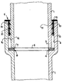
- the drawing shows an axial section in a purely schematic manner Area of the connection point between two socket pipe sections 1 in the assembled state.
- everybody Socket pipe section 1 points at its - in the assembled Condition of the flue pipe - upper end of a sleeve 2, in which the tip end 3 of the next upper socket pipe section 1 is inserted.
- a sealing ring 5 is attached, for. B. by gluing the from the inner edge of the sleeve base to the inner wall 6 of the Sleeve extends.
- the sealing ring 5 consists of a relative hard set and therefore pressure-resistant fleece made of ceramic or Mineral fiber that is sufficiently elastically deformable is in order with the lower end edge 7 of the tip end 3 to create a gas-tight seal.
- the through the sealing ring 5 created first seal is thus limited to the Area of the joint 8 between the sleeve base 4 and the Front edge 7 of the tip end 3.
- the elasticity of the Sealing ring 5 is sufficient to even with a certain Inclination of the upper sleeve pipe section in contact to stay with the front edge 7.
- a second seal in the form of a lip seal 9 with a cylindrical Carrier body 10 arranged, which consists of an elastomer Material, e.g. B. silicone rubber.
- the cylindrical Carrier body 10 has on its inner peripheral surface several - in the exemplary embodiment three - in the undeformed Condition radial circumferential sealing lips 11, the radial are sufficiently wide to cover the distance between the Inner circumference of the cylindrical support body 10 and the Outer circumference 12 of the tip end 3 more than to bridge and to lie on the outer circumference 12 in a sealing manner.
- the carrier body 10 in one piece with a flat Retaining ring 13 formed with the cylindrical part of the support body 10 forms a support shoulder 14.
- the support ribs are 15 in the axial direction of the lip seal 9 at the same height arranged with the sealing lips 11.
- the support ribs 15 can also extend to the sealing lips 11 be staggered so that, for example, a Support rib 15 is located centrally between two sealing lips 11.
- This embodiment then proves to be advantageous if the annular gap between the tip end 13 and the Socket inner wall 6 due to a corresponding Clash of tolerances is tight.
- the lip seal is then able by a wave-like deformation of the Carrier body 10 at the locations of the sealing lips 11 additionally give in.
- connection process for establishing the plug connection all that is required is to attach the elastomer Lip seal on the upper sleeve edge and that then inserting the tip end 3 of a Socket pipe section 1 until it bumps against the first Sealing ring 5.
- the part 13 of the elastomer Lip seal 9 prevents it from being drawn into the Annular gap 16.
- the sealing on the sealing ring 5 takes place by pressing the front edge 7 into the sealing ring 5 below the load of the smoke column above.
- the invention may also differ from the above described embodiment can be designed. So can the lip seal instead of directly on the sleeve be attached to the tip end, so that in this case the Stick the sealing lips outwards from the tip end.
- At least one at an angle to Sealing lip pointing to the base of the sleeve may be provided. if the Lip seal attached to the tip end accordingly the obliquely arranged sealing lip of the Muffenground gone.
- the term keramine or mineral fiber material also covers such fiber materials that are sufficient are heat-resistant and, if necessary, by a Additional treatment, sufficient in the prepared form Have elasticity.
- This can also be Glass fiber, especially quartz glass fiber, act.
- the Fiber material can be used as in the exemplary embodiment Tangled fiber fleece exist, but also in the form of a Fabric. In both cases it can be remembered that Elasticity and compressive strength and, if necessary, the Density due to embedding in or Impact impregnation with plastic material. So fiber materials embedded in plastic are higher Compressive strength and hardness known (Bakelite®). Also one Impregnation with expanded mica is possible Exposure to heat expands, so that the front edge of the tip end 3 is better covered by the sealing ring.
Landscapes
- Engineering & Computer Science (AREA)
- General Engineering & Computer Science (AREA)
- Mechanical Engineering (AREA)
- Architecture (AREA)
- Civil Engineering (AREA)
- Structural Engineering (AREA)
- Joints With Sleeves (AREA)
- Joints Allowing Movement (AREA)
- Sink And Installation For Waste Water (AREA)
- Gasket Seals (AREA)
Abstract
Description
Claims (14)
- Rauchrohr eines Kamins, das aus insbesondere keramischen Muffenrohr-Abschnitten (1) aufgebaut ist, wobei die Muffenrohr-Abschnitte an ihren Verbindungsstellen durch eine erste Dichtung (5) in der sich radial erstreckenden Fuge (8) zwischen dem Muffengrund (4) und dem Rand (7) des Spitzendes (3) und durch eine zweite Dichtung aus einem elastomeren Material in dem Ringspalt (16) zwischen der Muffeninnenwand (6) und dem Spitzende (3) abgedichtet sind, dadurch gekennzeichnet,
daß die erste Dichtung ein Dichtring (5) aus einem wärmebeständigen Fasermaterial und die zweite Dichtung aus elastomerem Material eine Lippendichtung (9) mit mindestens einer den Ringspalt (16) überbrückenden Dichtlippe (11) ist. - Rauchrohr nach Anspruch 1,
dadurch gekennzeichnet,
daß der Dichtring (5) an dem Muffengrund befestigt, z. B. angeklebt, ist. - Rauchrohr nach Anspruch 1 oder 2,
dadurch gekennzeichnet,
daß der Dichtring (5) aus einem druckfesten, gegebenenfalls kunststoffverstärkten Keramik- oder Mineralfaservlies besteht. - Rauchrohr nach einem der Ansprüche 1 bis 3,
dadurch gekennzeichnet,
daß die zweite Dichtung (9) einen zylindrischen Trägerkörper (10) aufweist, von dem mindestens eine nach innen gerichtete, ringförmig umlaufende Dichtlippe (11) vorspringt. - Rauchrohr nach Anspruch 4,
dadurch gekennzeichnet, daß der
Trägerkörper (10) an der Muffe gehalten ist und sich über eine Schulter (14) an dem oberen Muffenrand abstützt. - Rauchrohr nach einem der Ansprüche 1 bis 5,
dadurch gekennzeichnet,
daß die Lippendichtung (9) an der Muffe (2) befestigt, z. B. angeklebt oder aufgesteckt ist. - Rauchrohr nach einem der Ansprüche 4 bis 6,
dadurch gekennzeichnet,
daß an dem Trägerkörper (10) mehrere nach innen gerichtete Dichtlippen (11) vorgesehen sind. - Rauchrohr nach einem der Ansprüche 5 bis 7,
dadurch gekennzeichnet,
daß die Dichtlippe (11) bzw. Dichtlippen im unverformten Zustand schräg zum Muffengrund (4) weist bzw. weisen. - Rauchrohr nach einem der Ansprüche 1 bis 4,
dadurch gekennzeichnet,
daß die Lippendichtung an dem Spitzende (3) angeordnet ist. - Rauchrohr nach Anspruch 9,
dadurch gekennzeichnet,
daß die Lippendichtung mit ihrem zylindrischen Trägerkörper in einer Nut des Spitzendes formschlüssig aufgenommen ist. - Rauchrohr nach Anspruch 9 oder 10,
dadurch gekennzeichnet,
daß die Dichtlippe bzw. Dichtlippen im unverformten Zustand schräg von dem Muffengrund wegweist bzw. weisen. - Lippendichtung aus elastomerem Material zur Verwendung für die Abdichtung von Rauchrohr-Abschnitten (1) eines Kamins, mit einem zylindrischen Trägerkörper (10), an dessen innerer Umfangsfläche zumindest eine nach innen ragende umlaufende Dichtlippe (11) und an dessen äußerer Umfangsfläche zumindest eine nach außen ragende Stützrippe (15) angeordnet sind.
- Lippendichtung nach Anspruch 12,
dadurch gekennzeichnet,
daß sie mehrere, in Achsrichtung des Trägerkörpers (10) voneinander beabstandete Dichtlippen (11) und Stützrippen (15) aufweist. - Lippendichtung nach Anspruch 13,
dadurch gekennzeichnet,
daß die Stützrippen (15) axial zu den Dichtlippen (11) versetzt, z. B. jeweils mittig versetzt, angeordnet sind.
Applications Claiming Priority (2)
| Application Number | Priority Date | Filing Date | Title |
|---|---|---|---|
| DE29709874U | 1997-06-06 | ||
| DE29709874U DE29709874U1 (de) | 1997-06-06 | 1997-06-06 | Kamin-Rauchrohr aus Muffenrohr-Abschnitten und deren Abdichtung |
Publications (2)
| Publication Number | Publication Date |
|---|---|
| EP0882928A2 true EP0882928A2 (de) | 1998-12-09 |
| EP0882928A3 EP0882928A3 (de) | 1998-12-16 |
Family
ID=8041257
Family Applications (1)
| Application Number | Title | Priority Date | Filing Date |
|---|---|---|---|
| EP98110121A Ceased EP0882928A3 (de) | 1997-06-06 | 1998-06-03 | Kamin-Rauchrohr aus Muffenrohr-Abschnitten und deren Abdichtung |
Country Status (2)
| Country | Link |
|---|---|
| EP (1) | EP0882928A3 (de) |
| DE (1) | DE29709874U1 (de) |
Cited By (5)
| Publication number | Priority date | Publication date | Assignee | Title |
|---|---|---|---|---|
| NL1015628C2 (nl) * | 2000-07-06 | 2002-01-11 | Muelink & Grol Bv | Rookgasafvoerkanaal voorzien van koppelmiddelen voor het koppelen van een mannelijk eind van een eerste pijpdeel en een vrouwelijk eind van een tweede pijpdeel. |
| CN103047504A (zh) * | 2012-12-17 | 2013-04-17 | 冀州市中意复合材料有限公司 | 玻璃钢管承插接头的密封结构及修补方法 |
| CN110748708A (zh) * | 2019-11-24 | 2020-02-04 | 山西泫氏实业集团有限公司 | 一种穿楼板用预埋管件及定位装置 |
| CN111706729A (zh) * | 2020-07-01 | 2020-09-25 | 中国电建集团贵阳勘测设计研究院有限公司 | 一种具有固定输水球墨铸铁管接口的柔性结构 |
| CN116620240A (zh) * | 2023-06-25 | 2023-08-22 | 浙江锦安汽车零部件有限公司 | 轻型卡车用轻量化刹车泵系统 |
Families Citing this family (8)
| Publication number | Priority date | Publication date | Assignee | Title |
|---|---|---|---|---|
| DE29801063U1 (de) * | 1998-01-23 | 1999-03-25 | Erlus Baustoffwerke AG, 84088 Neufahrn | Kamin-Rauchrohr aus Muffenrohr-Abschnitten und deren Abdichtung |
| DE29822491U1 (de) | 1998-12-17 | 1999-03-04 | Erlus Baustoffwerke AG, 84088 Neufahrn | Aus mehreren Rohrabschnitten aufgebautes Rauchrohr eines Kamins und Dichtring aus Keramikfasermaterial hierzu |
| IT1305428B1 (it) * | 1998-12-17 | 2001-05-04 | Cast S R L | Condotto di scarico gas di combustione ed aspirazione gas comburenti |
| ATE280357T1 (de) * | 1999-01-14 | 2004-11-15 | Schiedel Gmbh & Co | Innenrohr für einen schornstein |
| DE29911423U1 (de) | 1999-07-02 | 1999-10-07 | SP-Beton GmbH & Co. KG, 21481 Lauenburg | Dichtung |
| DE19939398A1 (de) * | 1999-08-19 | 2001-03-08 | Waldsassen Ziegelwerk Ag | Muffenrohranordnung für eine Abgasleitung und Zentriervorrichtung hierfür |
| CN109296171B (zh) * | 2018-11-20 | 2022-08-23 | 广州市彩蝶节能技术有限公司 | 一种住宅排气道系统 |
| CN112344087A (zh) * | 2020-11-23 | 2021-02-09 | 江西省陛快管道科技有限公司 | 一种不锈钢管承插连接专用阀门 |
Citations (2)
| Publication number | Priority date | Publication date | Assignee | Title |
|---|---|---|---|---|
| DE29510018U1 (de) | 1995-06-21 | 1995-10-19 | Thoma, Norbert, 93057 Regensburg | Abdichtvorrichtung |
| DE4443603A1 (de) | 1994-12-07 | 1996-06-13 | Steinzeugwerk Ponholz Gmbh & C | Fugenverbindung für Rohre, insbesondere Kaminrohre aus Keramik |
Family Cites Families (5)
| Publication number | Priority date | Publication date | Assignee | Title |
|---|---|---|---|---|
| US2032492A (en) * | 1934-10-31 | 1936-03-03 | Goodrich Co B F | Pipe joint assembly |
| US3046028A (en) * | 1959-12-01 | 1962-07-24 | Hamilton Kent Mfg Company | Gasket and use thereof |
| GB1222364A (en) * | 1967-06-20 | 1971-02-10 | Schionning & Arve De Forenede | Sanitary pipe joints |
| US3573871A (en) * | 1968-11-12 | 1971-04-06 | Tyler Pipe Ind Inc | Gasket for bell-type pipe joint |
| DE19542580A1 (de) * | 1995-11-15 | 1997-05-22 | Erlus Baustoffwerke | Aus mehreren Rohrabschnitten aufgebautes Rauchrohr eines Kamins |
-
1997
- 1997-06-06 DE DE29709874U patent/DE29709874U1/de not_active Expired - Lifetime
-
1998
- 1998-06-03 EP EP98110121A patent/EP0882928A3/de not_active Ceased
Patent Citations (2)
| Publication number | Priority date | Publication date | Assignee | Title |
|---|---|---|---|---|
| DE4443603A1 (de) | 1994-12-07 | 1996-06-13 | Steinzeugwerk Ponholz Gmbh & C | Fugenverbindung für Rohre, insbesondere Kaminrohre aus Keramik |
| DE29510018U1 (de) | 1995-06-21 | 1995-10-19 | Thoma, Norbert, 93057 Regensburg | Abdichtvorrichtung |
Cited By (5)
| Publication number | Priority date | Publication date | Assignee | Title |
|---|---|---|---|---|
| NL1015628C2 (nl) * | 2000-07-06 | 2002-01-11 | Muelink & Grol Bv | Rookgasafvoerkanaal voorzien van koppelmiddelen voor het koppelen van een mannelijk eind van een eerste pijpdeel en een vrouwelijk eind van een tweede pijpdeel. |
| CN103047504A (zh) * | 2012-12-17 | 2013-04-17 | 冀州市中意复合材料有限公司 | 玻璃钢管承插接头的密封结构及修补方法 |
| CN110748708A (zh) * | 2019-11-24 | 2020-02-04 | 山西泫氏实业集团有限公司 | 一种穿楼板用预埋管件及定位装置 |
| CN111706729A (zh) * | 2020-07-01 | 2020-09-25 | 中国电建集团贵阳勘测设计研究院有限公司 | 一种具有固定输水球墨铸铁管接口的柔性结构 |
| CN116620240A (zh) * | 2023-06-25 | 2023-08-22 | 浙江锦安汽车零部件有限公司 | 轻型卡车用轻量化刹车泵系统 |
Also Published As
| Publication number | Publication date |
|---|---|
| DE29709874U1 (de) | 1997-09-04 |
| EP0882928A3 (de) | 1998-12-16 |
Similar Documents
| Publication | Publication Date | Title |
|---|---|---|
| EP0882928A2 (de) | Kamin-Rauchrohr aus Muffenrohr-Abschnitten und deren Abdichtung | |
| DE6926384U (de) | Flammrohr fuer eine gasturbinen - brennkammer | |
| DE2531318A1 (de) | Rohrsteckverbindung | |
| DE3247452C1 (de) | Rohrverbindung | |
| DE2754984A1 (de) | Schub- und zugsicherung fuer rohrverbindungen | |
| EP0611855B1 (de) | Anordnung zum Verbinden zweier Rohrabschnitte des keramischen Innenrohres eines Schornsteins | |
| EP0774624A2 (de) | Aus mehreren Rohrabschnitten aufgebautes Rauchrohr eines Kamins | |
| DE19800512C2 (de) | Muffensteckverbindung für Rohre, insbesondere Abgas- und Kaminrohre | |
| DE6923771U (de) | Manschettendichtung fuer die innenabdichtung von rohrstoessen bei im erdreich verlegten rohrleitungen | |
| DE19529473C1 (de) | Mehrzweckbauteil mit Federelementen | |
| EP1006307A1 (de) | Steckkupplung | |
| EP0931982A2 (de) | Kamin-Rauchrohr aus Muffenrohrabschnitten und deren Abdichtung | |
| DE9412445U1 (de) | Unlösbare Rohrverbindung | |
| DE19547901A1 (de) | Schornsteinrohr aus keramischem Material | |
| DE29714955U1 (de) | Verbindung zwischen einer Rohrkupplung und einem Rohrende sowie Rohrkupplung hierfür | |
| DE4409137C1 (de) | Rohrkupplung | |
| DE3616535C2 (de) | Kabelmuffe aus einem Muffenrohr und aus zwei seitlich sich anschließenden, schrumpfbaren Muffenköpfen | |
| DE29518106U1 (de) | Aus mehreren Rohrabschnitten aufgebautes Rauchrohr eines Kamins | |
| EP1518069B1 (de) | Abdichtung für eine einsteckverbindung bei rohren | |
| DE2123286C (de) | Abdichtung fur den Innenraum einer Drehgelenkkupplung | |
| DE4315958A1 (de) | Rohrdichtung | |
| DE4345183A1 (de) | Anordnung zum Verbinden zweier Rohrabschnitte des keramischen Innenrohres eines Schornsteins | |
| DE3515477A1 (de) | Sickerleitungs-rohrstrecke | |
| DE2713767A1 (de) | Dichtungshuelse fuer muffenrohrverbindungen | |
| DE202004002374U1 (de) | Rohreinrichtung mit Adapter |
Legal Events
| Date | Code | Title | Description |
|---|---|---|---|
| PUAI | Public reference made under article 153(3) epc to a published international application that has entered the european phase |
Free format text: ORIGINAL CODE: 0009012 |
|
| PUAL | Search report despatched |
Free format text: ORIGINAL CODE: 0009013 |
|
| AK | Designated contracting states |
Kind code of ref document: A2 Designated state(s): AT CH DE FR IT LI |
|
| AX | Request for extension of the european patent |
Free format text: AL;LT;LV;MK;RO;SI |
|
| AK | Designated contracting states |
Kind code of ref document: A3 Designated state(s): AT BE CH CY DE DK ES FI FR GB GR IE IT LI LU MC NL PT SE |
|
| AX | Request for extension of the european patent |
Free format text: AL;LT;LV;MK;RO;SI |
|
| AKX | Designation fees paid |
Free format text: AT CH DE FR IT LI |
|
| 17P | Request for examination filed |
Effective date: 19990804 |
|
| 17Q | First examination report despatched |
Effective date: 20011114 |
|
| STAA | Information on the status of an ep patent application or granted ep patent |
Free format text: STATUS: THE APPLICATION HAS BEEN REFUSED |
|
| 18R | Application refused |
Effective date: 20021028 |