EP0882989B1 - Capteur électro-optique à diviseur de tension massif - Google Patents
Capteur électro-optique à diviseur de tension massif Download PDFInfo
- Publication number
- EP0882989B1 EP0882989B1 EP98401152A EP98401152A EP0882989B1 EP 0882989 B1 EP0882989 B1 EP 0882989B1 EP 98401152 A EP98401152 A EP 98401152A EP 98401152 A EP98401152 A EP 98401152A EP 0882989 B1 EP0882989 B1 EP 0882989B1
- Authority
- EP
- European Patent Office
- Prior art keywords
- voltage
- sensor according
- voltage divider
- pockels cell
- electro
- Prior art date
- Legal status (The legal status is an assumption and is not a legal conclusion. Google has not performed a legal analysis and makes no representation as to the accuracy of the status listed.)
- Expired - Lifetime
Links
Images

Classifications
-
- G—PHYSICS
- G01—MEASURING; TESTING
- G01R—MEASURING ELECTRIC VARIABLES; MEASURING MAGNETIC VARIABLES
- G01R15/00—Details of measuring arrangements of the types provided for in groups G01R17/00 - G01R29/00, G01R33/00 - G01R33/26 or G01R35/00
- G01R15/04—Voltage dividers
- G01R15/06—Voltage dividers having reactive components, e.g. capacitive transformer
-
- G—PHYSICS
- G01—MEASURING; TESTING
- G01R—MEASURING ELECTRIC VARIABLES; MEASURING MAGNETIC VARIABLES
- G01R15/00—Details of measuring arrangements of the types provided for in groups G01R17/00 - G01R29/00, G01R33/00 - G01R33/26 or G01R35/00
- G01R15/14—Adaptations providing voltage or current isolation, e.g. for high-voltage or high-current networks
- G01R15/24—Adaptations providing voltage or current isolation, e.g. for high-voltage or high-current networks using light-modulating devices
- G01R15/247—Details of the circuitry or construction of devices covered by G01R15/241 - G01R15/246
-
- H—ELECTRICITY
- H02—GENERATION; CONVERSION OR DISTRIBUTION OF ELECTRIC POWER
- H02B—BOARDS, SUBSTATIONS OR SWITCHING ARRANGEMENTS FOR THE SUPPLY OR DISTRIBUTION OF ELECTRIC POWER
- H02B13/00—Arrangement of switchgear in which switches are enclosed in, or structurally associated with, a casing, e.g. cubicle
- H02B13/02—Arrangement of switchgear in which switches are enclosed in, or structurally associated with, a casing, e.g. cubicle with metal casing
- H02B13/035—Gas-insulated switchgear
- H02B13/0356—Mounting of monitoring devices, e.g. current transformers
Definitions
- the invention relates to an electro-optical voltage sensor for determine the voltage of a power line, including a divider voltage connected to the power line and to ground and having two insulating compartments separated by a connected intermediate electrode to a Pockels cell, the intermediate electrode providing the Pockels cell a voltage reduced from the voltage supplied by the line voltage divider.
- Such a sensor is used in distribution networks to determine the value of the voltage of the power lines necessary for the "Counting” of electrical transit and “Protection” of networks.
- the Pockels cell comprises a crystal electro-optic, for example a Bismuth and Germanium oxide or Bismuth and Silicon.
- the Pockels effect designates the appearance of a birefringence of the crystal caused by the application of a voltage electric between two faces of the crystal coated with a conductive deposit.
- the Pockels cell also includes an optical fiber input connected to a light emitting diode emitting a beam luminous incident through a polarizer and a phase shifting blade. In passing through the electro-optical crystal the incident light beam sees its polarization vary.
- An analyzer arranged on the beam path transmitted light transforms the polarization variation at the output of the crystal in a variation of light intensity transported by a fiber output optics to a photodiode detector located in a electronic remote.
- the polarization variation depends on the voltage applied between the conductive faces of the electro-optical crystal.
- the light power instant received by the photodiode related to continuous power emitted by the light-emitting diode depends on the voltage applied U as a sine of the product k * U, where k is a characteristic electro-optical coupling coefficient of the crystal Pockels cell used.
- the Pockels cell is used to determine a voltage applied U up to a typical value of 10,000 volts, usually designated by quarter wave voltage of the electro-optical crystal.
- a first solution to overcome this problem consists in split the incident light beam to produce another trigonometric variation of the light power.
- a second solution consists in associating the Pockels cell to a voltage divider.
- the latter generally includes a column capacitive formed of elementary capacities all identical and consisting for example of aluminum sheets serving as reinforcements separated by insulating sheets of paper or polypropylene, the assembly being immersed in an insulating liquid for example at oil base.
- An intermediate electrode electrically connected to one of the conductive faces of the electro-optical crystal of the Pockels cell separates the capacitive column into two insulating compartments.
- a total tension applied to the column generates a reduced tension at the Pockels cell, the ratio between the tensions being determined by the capacities of two column compartments.
- the Pockels is associated with a capacitive column arranged inside and over the entire length of an insulator supporting the power line.
- the length of the insulator filled with a pressurized gas is chosen by function of the voltage of the power line so that the capacity of the two compartments allows to sufficiently divide the line voltage so that the reduced voltage is less than the voltage quarter wave of the electro-optical crystal of the Pockels cell used.
- the increase in resulting temperature and pressure generally lead an explosion of the insulator, whether it is made of a glassy material, for example porcelain, or composite.
- the capacitive column which is in practice arranged vertically in the insulator can undergo variations over time dimension of mechanical origin due to a crushing different from elementary capacities between those located at the bottom and those located at the top of the column, this phenomenon can be even more marked in the case where the oil-based insulation liquid is replaced by a gas.
- dimensional variations of thermal origin may result from a different expansion of elementary capacities under the effect of a temperature gradient between the bottom and the top of the column.
- the object of the invention is therefore to propose an electro-optical sensor of tension comprising a Pockels cell associated with a voltage divider which offers increased safety with regard to risks of short circuit and which gives the sensor high reliability and high measurement accuracy.
- the subject of the invention is an electro-optical sensor for voltage to determine the voltage of a power line, said sensor comprising a voltage divider which can be connected to the power line and to a ground and having two insulating compartments separated by an electrode intermediate as well as a Pockels cell, said intermediate electrode being connected to the Pockels cell and supplying the Pockels cell with a voltage reduced by the voltage can be supplied by the power line to the voltage divider, characterized in that each insulating compartment is massive and consists of a dielectric block homogeneous.
- the two insulating compartments made up of a block homogeneous dielectric, the block term indicating that each compartment is massive, gives the electro-optical sensor reliability against short circuits much higher than that capacitive column voltage dividers described above.
- the mechanical strength of the voltage divider is also strongly improved, the crushing resistance of the blocks being much higher to that of the elementary capacities with conductive and insulating sheets.
- Figure 1 is a schematic section of a voltage divider at two homogeneous dielectric blocks.
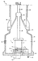
- Figure 2 shows in section an electro-optical sensor of voltage comprising a voltage divider associated with a Pockels.
- a voltage divider 1 comprises two blocks homogeneous dielectrics 2 and 3.
- Block 2 designated below by block upper block and block 3 referred to below as lower block have a cylindrical shape and have an identical section, for example circular.
- the straight sections of the two blocks are coated with a deposit conductor for example of aluminum obtained by evaporation under vacuum or by any other chemical process.
- the two blocks are then assembled by simple pressure or by conductive bonding. Deposits and the conductive bonding together form the intermediate electrode 5.
- the voltage divider is itself mounted between two frames opposite 7 and 9.
- the lower block 3 has an axial recess 11 for allow the passage of a contact wire 13 connected to the electrode intermediate 5.
- the voltage divider of FIG. 1 makes it possible to obtain a continuous ratio by the kiss of the thicknesses e 2 and e 3 .
- the two compartments of the voltage divider are made of glass or glass ceramic blocks. These latter offer relative dielectric constants on the order of 8 plus higher than those of glasses on the order of 3. These materials increase the overall capacity of the screw tension divider with regard to parasitic capacities.
- an electro-optical voltage sensor 10 comprises a voltage divider 1 such as that described above arranged inside a shielded enclosure 20 for example metal and filled with an insulating gas 21 under pressure for example hexafluoride of sulfur SF 6 or nitrogen N 2 sec.
- Another neutral and dry gaseous insulator may be suitable for the filling of the shielded enclosure, as well as a solid insulation by example in polyethylene or silicone, interesting both on the economic plan and for the respect of standards of use with respect to the protection of the environment.
- Gas insulators compatible with dielectric blocks homogeneous voltage divider eliminates the need for insulation based on oil and thus considerably limit the risks explosion in the event of a short circuit between the armatures of the divider voltage.
- the shielded enclosure is electrically connected by its base 22 to a ground 15.
- a frame 12 resting inside the shielded enclosure 20 on the base 22 supports the voltage divider 1 and contains a Pockels 4 of the type described above.
- a conductive wire 13 ensures contact between the electrode intermediate 5 and a conductive face of the electro-optical crystal of the Pockels cell 4, the other conductive face being connected to ground 15. In this way, a total voltage V applied to the divider of voltage generates a reduced voltage U at a time on the lower block 3 and on the Pockels cell whose electrical impedance is approximately a thousand times greater than that of the lower block 3.
- the Pockels cell 4 contains an optical fiber 17 associated with a light emitting diode and an optical fiber 19 associated with a receiving photodiode, connected to an electronic unit (not shown) for acquiring signals representative of the continuous light power emitted and of the instantaneous light power received.
- Signal processing gives access to the reduced voltage U and calculates the total voltage V from the thicknesses e 2 and e 3 of the two blocks of the voltage divider.
- the frame can contain at least two cells of Pockels ensuring a redundant function.
- An insulator 25 for example made of porcelain or composite of cylindrical or frustoconical shape is assembled mechanically for example by screwing to the shielded enclosure at the level of a fixing shoulder 23.
- the insulator 25 is filled with a gas under pressure generally of the same nature as that 21 contained in the shielded enclosure 20, for example sulfur hexafluoride SF 6 .
- a support cone 27 ensures the maintenance of an electrical conductor 28 from the power line. It can also provide a sealed separation between the insulator 25 and the shielded enclosure 20.
- the electrical conductor 28 is disposed inside the insulator 25 and extends into the shielded enclosure via a annular opening 29 formed at the top of the support cone 27.
- the electrical conductor 28 connects the armature 7 of the dielectric block upper 2 of voltage divider 1 to a non-electrical line shown supported by insulator 25.
- the power line carrying a voltage V provides the same voltage to the divider of voltage, the intermediate electrode 5 providing a reduced voltage U to the Pockels cell.
- the determination of the reduced voltage U by the electro-optical sensor provides access to line voltage V electric.
- Figure 2 highlights the advantages of the electro-optical sensor of tension according to the invention.
- the insulator which supports the line voltage contains only the electrical conductor which transmits the voltage up to the voltage divider arranged inside the enclosure Armored.
- the risk of short circuit is limited to the shielded enclosure designed to withstand an increase in temperature and pressure of the insulating gas.
- a rupture disc 30 freeing an orifice when the pressure exceeds a certain threshold is formed in the wall of the shielded enclosure so that its breaking limit is not reached.
- electro-optical voltage sensor presents a security very high with regard to explosion risks.
- the location of the line voltage inside the shielded enclosure takes advantage of the compactness of the voltage divider, in particular in the case where the two blocks Homogeneous dielectrics are made of glass ceramics.
- the shielded enclosure ensures homogenization of the temperature of the insulating gas in contact with the voltage divider.
- the two homogeneous dielectric blocks are thus at roughly the same temperature.
- the shielded enclosure also ensures total protection against electromagnetic interference which may come from other external live conductors located at near the electro-optical sensor. The measurement accuracy of the power line voltage is therefore guaranteed.
- the electro-optical voltage sensor has both a mechanical and thermal stability which guarantees a functioning of high accuracy and reliability over time without special maintenance.
Landscapes
- Physics & Mathematics (AREA)
- General Physics & Mathematics (AREA)
- Engineering & Computer Science (AREA)
- Power Engineering (AREA)
- Measuring Instrument Details And Bridges, And Automatic Balancing Devices (AREA)
- Measurement Of Current Or Voltage (AREA)
Description
Claims (10)
- Capteur électro-optique de tension (10) pour déterminer la tension d'une ligne électrique, ledit capteur comprenant un diviseur de tension (1) pouvant être relié à la ligne électrique et à une masse (15) et ayant deux compartiments isolants (2, 3) séparés par une électrode intermédiaire (5) ainsi qu'une cellule de Pockels, ladite électrode intermédiaire étant reliée à la cellule de Pockels et fournissant à la cellule de Pockels une tension réduite de la tension pouvant être fournie par la ligne électrique au diviseur de tension (1), caractérisé en ce que chaque compartiment isolant (2, 3) est massif et est constitué d'un bloc diélectrique homogène.
- Le capteur selon la revendication 1, dans lequel chaque compartiment (2, 3) est constitué d'un bloc de verre ou de vitrocéramique.
- Le capteur selon la revendication 1 ou 2, dans lequel les deux blocs diélectriques homogènes (2, 3) sont de forme cylindrique et possèdent une même section.
- Le capteur selon la revendication 3, dans lequel les sections des deux blocs sont revêtues d'un dépôt conducteur.
- Le capteur selon la revendication 4, dans lequel l'électrode intermédiaire (5) est formée par un collage conducteur des deux blocs diélectriques homogènes (2, 3).
- Le capteur selon la revendication 3, dans lequel l'un (3) des deux blocs diélectriques homogènes comporte un évidement axial (11) pour le passage d'un fil conducteur (13) reliant l'électrode intermédiaire (5) à la cellule de Pockels (4).
- Le capteur selon l'une des revendications précédentes, dans lequel le diviseur de tension (1) et la cellule de Pockels (4) sont disposés dans une enceinte blindée (20).
- Le capteur seton la revendication 7, dans lequel le diviseur de tension (1) peut être relié à la ligne électrique par un conducteur électrique (28) qui est disposé à l'intérieur d'un isolateur (25) et qui se prolonge à l'intérieur de l'enceinte blindée (20).
- Le capteur selon la revendication 7 ou 8, dans lequel l'enceinte blindée (20) ou l'isolateur (25) sont remplis d'un gaz neutre et sec sous une pression moyenne inférieure à 2 bars.
- Le capteur selon la revendication 9, dans lequel l'enceinte blindée (20) possède un disque de rupture (30).
Applications Claiming Priority (2)
| Application Number | Priority Date | Filing Date | Title |
|---|---|---|---|
| FR9707012 | 1997-06-06 | ||
| FR9707012A FR2764390B1 (fr) | 1997-06-06 | 1997-06-06 | Capteur electro-optique a diviseur de tension massif |
Publications (2)
| Publication Number | Publication Date |
|---|---|
| EP0882989A1 EP0882989A1 (fr) | 1998-12-09 |
| EP0882989B1 true EP0882989B1 (fr) | 2004-09-22 |
Family
ID=9507683
Family Applications (1)
| Application Number | Title | Priority Date | Filing Date |
|---|---|---|---|
| EP98401152A Expired - Lifetime EP0882989B1 (fr) | 1997-06-06 | 1998-05-14 | Capteur électro-optique à diviseur de tension massif |
Country Status (6)
| Country | Link |
|---|---|
| US (1) | US6127817A (fr) |
| EP (1) | EP0882989B1 (fr) |
| JP (1) | JPH1114669A (fr) |
| CA (1) | CA2239077A1 (fr) |
| DE (1) | DE69826363T2 (fr) |
| FR (1) | FR2764390B1 (fr) |
Families Citing this family (13)
| Publication number | Priority date | Publication date | Assignee | Title |
|---|---|---|---|---|
| US6380725B1 (en) * | 2000-02-15 | 2002-04-30 | Nxtphase Corporation | Voltage sensor |
| US7173956B2 (en) | 2003-02-12 | 2007-02-06 | Northrop Grumman Corporation | Electrically controlled uniform or graded reflectivity electro-optic mirror |
| US7199571B2 (en) * | 2004-07-27 | 2007-04-03 | Optisense Network, Inc. | Probe apparatus for use in a separable connector, and systems including same |
| US8384363B2 (en) * | 2005-11-11 | 2013-02-26 | L&L Engineering, Llc | Buck DC-to-DC converter and method |
| FI118833B (fi) * | 2006-10-12 | 2008-03-31 | Kone Corp | Seurantajärjestelmä |
| ITBO20080079U1 (it) * | 2008-10-30 | 2010-04-30 | Lorenzo Peretto | Sistema costruttivo per un sensore capacitivo. |
| CN102928640B (zh) * | 2011-09-26 | 2013-06-05 | 北京航天时代光电科技有限公司 | 悬浮电极式光学电压互感器 |
| US9121872B2 (en) * | 2011-09-26 | 2015-09-01 | Beijing Aerospace Times Optical-Electronic Technology Co. Ltd. | Electro-optic effect based optical voltage transformer |
| CN103424594B (zh) * | 2013-07-26 | 2016-08-31 | 易能乾元(北京)电力科技有限公司 | 一种高压传感式光学电压互感器 |
| CN103472278B (zh) * | 2013-09-05 | 2015-11-18 | 江苏思源赫兹互感器有限公司 | 一种支柱式光纤电压互感器 |
| EP2887074B1 (fr) | 2013-12-18 | 2020-11-25 | 3M Innovative Properties Company | Capteur de tension |
| CN104597305B (zh) * | 2015-01-07 | 2017-11-14 | 马鞍山万兆科技有限公司 | 一种光学电压互感器及其封装方法 |
| WO2025189070A1 (fr) * | 2024-03-07 | 2025-09-12 | Hubbell Incorporated | Systèmes de détection de tension optique et ensembles à cristaux électro-optiques |
Family Cites Families (7)
| Publication number | Priority date | Publication date | Assignee | Title |
|---|---|---|---|---|
| DE2341073B2 (de) * | 1973-08-10 | 1980-01-10 | Siemens Ag, 1000 Berlin Und 8000 Muenchen | Meßeinrichtung für die Spannung in einer gekapselten Hochspannungsschaltanlage |
| JPS58150869A (ja) * | 1982-03-03 | 1983-09-07 | Toshiba Corp | 信号測定方式 |
| JP2867505B2 (ja) * | 1989-12-04 | 1999-03-08 | 三菱電機株式会社 | 計器用変圧器 |
| JP2933147B2 (ja) * | 1991-09-05 | 1999-08-09 | 松下電器産業株式会社 | 電流・電圧センサー |
| US5635831A (en) * | 1991-12-11 | 1997-06-03 | Imatran Voima Oy | Optical voltage and electric field sensor based on the pockels effect |
| DE4205509A1 (de) * | 1992-02-24 | 1993-08-26 | Mwb Pruefsysteme Gmbh | Verfahren und sensor zum messen von elektrischen spannungen und/oder elektrischen feldstaerken |
| JPH05273256A (ja) * | 1992-03-24 | 1993-10-22 | Furukawa Electric Co Ltd:The | 碍子内蔵型光電圧センサ |
-
1997
- 1997-06-06 FR FR9707012A patent/FR2764390B1/fr not_active Expired - Fee Related
-
1998
- 1998-05-14 DE DE69826363T patent/DE69826363T2/de not_active Expired - Fee Related
- 1998-05-14 EP EP98401152A patent/EP0882989B1/fr not_active Expired - Lifetime
- 1998-06-05 US US09/092,084 patent/US6127817A/en not_active Expired - Fee Related
- 1998-06-05 CA CA002239077A patent/CA2239077A1/fr not_active Abandoned
- 1998-06-05 JP JP10158188A patent/JPH1114669A/ja active Pending
Also Published As
| Publication number | Publication date |
|---|---|
| JPH1114669A (ja) | 1999-01-22 |
| FR2764390A1 (fr) | 1998-12-11 |
| CA2239077A1 (fr) | 1998-12-06 |
| FR2764390B1 (fr) | 1999-07-16 |
| US6127817A (en) | 2000-10-03 |
| EP0882989A1 (fr) | 1998-12-09 |
| DE69826363D1 (de) | 2004-10-28 |
| DE69826363T2 (de) | 2006-02-09 |
Similar Documents
| Publication | Publication Date | Title |
|---|---|---|
| EP0882989A1 (fr) | Capteur électro-optique à diviseur de tension massif | |
| EP0025586A1 (fr) | Dispositif de couplage optique | |
| WO2010007266A1 (fr) | Detecteur bolometrique d'ondes electromagnetiques | |
| EP2199809A1 (fr) | Dispositif diviseur capacitif, capteur de tension, module de déclencheur et appareil de protection électrique pourvus d'un tel dispositif | |
| FR2998376A1 (fr) | Capteur de tension de ligne a tres haute tension a courant continu | |
| WO1996026554A1 (fr) | Dephaseur hyperfrequence et application a une antenne reseaux | |
| FR2598574A1 (fr) | Procede et dispositif optiques de transmission de donnees a multiplexage de frequence | |
| EP3268754A1 (fr) | Capteur de courant pour mesurer un courant alternatif | |
| FR2533705A1 (fr) | Detecteur de concentration ionique dans un liquide | |
| EP1715315A1 (fr) | Détecteur bolométrique, dispositif de détection d'ondes électromagnétiques submillimétriques et millimétriques mettant en oeuvre un tel détecteur | |
| EP0089275A1 (fr) | Dispositif interferométrique de mesure de courant électrique à fibres optique | |
| FR3067162A1 (fr) | Cable de connexion pour reseau haute tension a courant continu, dispositif et procede associe | |
| CA2083125C (fr) | Dispositif optique de mesure du courant dans une installation a enveloppe metallique a la terre | |
| FR2647552A1 (fr) | Systeme de mesure de signaux electriques a l'aide d'impulsions optiques ultracourtes | |
| EP0356302A1 (fr) | Procédé et dispositif de filtrage optique et de photodétection de signaux modulés en intensité | |
| FR3114171A1 (fr) | Source de tension et procédé de calibration de cette source de tension | |
| EP1093563A1 (fr) | Dispositif de mesure topographique | |
| FR3079928A1 (fr) | Capteur passif differentiel a base de resonateurs a ondes elastiques pour mesure de detection de contact et de mesure de temperature | |
| FR2472880A1 (fr) | Dispositif de controle automatique de gain a action optique dans un systeme de transmission de signaux electriques par liaison optique | |
| EP1688974B1 (fr) | Condensateur à haute stabilité thermique pour des mesures sur des lignes haute-tension | |
| EP0565464A1 (fr) | Procédé pour amortir des ondes électromagnétiques, notamment dans une enceinte de Faraday | |
| WO2013064788A1 (fr) | Procede et dispositif de mesure d'une tension | |
| WO2013117682A1 (fr) | Dispositif de mesure de courant hvdc large bande passante, tres haute precision | |
| FR2686423A1 (fr) | Boitier polarimetrique de mesure de l'angle de faraday. | |
| WO2004059831A1 (fr) | Oscillateur hyperfrequences a tres haute stabilite |
Legal Events
| Date | Code | Title | Description |
|---|---|---|---|
| PUAI | Public reference made under article 153(3) epc to a published international application that has entered the european phase |
Free format text: ORIGINAL CODE: 0009012 |
|
| AK | Designated contracting states |
Kind code of ref document: A1 Designated state(s): CH DE ES GB IT LI NL SE |
|
| AX | Request for extension of the european patent |
Free format text: AL;LT;LV;MK;RO;SI |
|
| AKX | Designation fees paid |
Free format text: CH DE ES GB IT LI NL SE |
|
| 17P | Request for examination filed |
Effective date: 19990609 |
|
| GRAP | Despatch of communication of intention to grant a patent |
Free format text: ORIGINAL CODE: EPIDOSNIGR1 |
|
| GRAS | Grant fee paid |
Free format text: ORIGINAL CODE: EPIDOSNIGR3 |
|
| GRAA | (expected) grant |
Free format text: ORIGINAL CODE: 0009210 |
|
| AK | Designated contracting states |
Kind code of ref document: B1 Designated state(s): CH DE ES GB IT LI NL SE |
|
| PG25 | Lapsed in a contracting state [announced via postgrant information from national office to epo] |
Ref country code: NL Free format text: LAPSE BECAUSE OF FAILURE TO SUBMIT A TRANSLATION OF THE DESCRIPTION OR TO PAY THE FEE WITHIN THE PRESCRIBED TIME-LIMIT Effective date: 20040922 Ref country code: IT Free format text: LAPSE BECAUSE OF FAILURE TO SUBMIT A TRANSLATION OF THE DESCRIPTION OR TO PAY THE FEE WITHIN THE PRE;WARNING: LAPSES OF ITALIAN PATENTS WITH EFFECTIVE DATE BEFORE 2007 MAY HAVE OCCURRED AT ANY TIME BEFORE 2007. THE CORRECT EFFECTIVE DATE MAY BE DIFFERENT FROM THE ONE RECORDED.SCRIBED TIME-LIMIT Effective date: 20040922 |
|
| REG | Reference to a national code |
Ref country code: GB Ref legal event code: FG4D Free format text: NOT ENGLISH |
|
| REG | Reference to a national code |
Ref country code: CH Ref legal event code: EP |
|
| REF | Corresponds to: |
Ref document number: 69826363 Country of ref document: DE Date of ref document: 20041028 Kind code of ref document: P |
|
| RAP2 | Party data changed (patent owner data changed or rights of a patent transferred) |
Owner name: ALSTOM T&D TRANSFORMATEURS DE MESURE SA |
|
| PG25 | Lapsed in a contracting state [announced via postgrant information from national office to epo] |
Ref country code: ES Free format text: LAPSE BECAUSE OF FAILURE TO SUBMIT A TRANSLATION OF THE DESCRIPTION OR TO PAY THE FEE WITHIN THE PRESCRIBED TIME-LIMIT Effective date: 20050102 |
|
| REG | Reference to a national code |
Ref country code: SE Ref legal event code: TRGR |
|
| RAP2 | Party data changed (patent owner data changed or rights of a patent transferred) |
Owner name: AREVA T&D TRANSFORMATEURS DE MESURE SA |
|
| NLT2 | Nl: modifications (of names), taken from the european patent patent bulletin |
Owner name: ALSTOM T&D TRANSFORMATEURS DE MESURE SA |
|
| GBT | Gb: translation of ep patent filed (gb section 77(6)(a)/1977) |
Effective date: 20050125 |
|
| NLT2 | Nl: modifications (of names), taken from the european patent patent bulletin |
Owner name: AREVA T&D TRANSFORMATEURS DE MESURE SA |
|
| NLV1 | Nl: lapsed or annulled due to failure to fulfill the requirements of art. 29p and 29m of the patents act | ||
| PG25 | Lapsed in a contracting state [announced via postgrant information from national office to epo] |
Ref country code: GB Free format text: LAPSE BECAUSE OF NON-PAYMENT OF DUE FEES Effective date: 20050514 |
|
| PG25 | Lapsed in a contracting state [announced via postgrant information from national office to epo] |
Ref country code: SE Free format text: LAPSE BECAUSE OF NON-PAYMENT OF DUE FEES Effective date: 20050515 |
|
| PG25 | Lapsed in a contracting state [announced via postgrant information from national office to epo] |
Ref country code: LI Free format text: LAPSE BECAUSE OF NON-PAYMENT OF DUE FEES Effective date: 20050531 Ref country code: CH Free format text: LAPSE BECAUSE OF NON-PAYMENT OF DUE FEES Effective date: 20050531 |
|
| PLBE | No opposition filed within time limit |
Free format text: ORIGINAL CODE: 0009261 |
|
| STAA | Information on the status of an ep patent application or granted ep patent |
Free format text: STATUS: NO OPPOSITION FILED WITHIN TIME LIMIT |
|
| 26N | No opposition filed |
Effective date: 20050623 |
|
| PG25 | Lapsed in a contracting state [announced via postgrant information from national office to epo] |
Ref country code: DE Free format text: LAPSE BECAUSE OF NON-PAYMENT OF DUE FEES Effective date: 20051201 |
|
| REG | Reference to a national code |
Ref country code: CH Ref legal event code: PL |
|
| EUG | Se: european patent has lapsed | ||
| GBPC | Gb: european patent ceased through non-payment of renewal fee |
Effective date: 20050514 |