EP0883046A1 - System zur Vorhersage der Überhitzung des Motors eines Kühlerverdichters - Google Patents
System zur Vorhersage der Überhitzung des Motors eines Kühlerverdichters Download PDFInfo
- Publication number
- EP0883046A1 EP0883046A1 EP98303678A EP98303678A EP0883046A1 EP 0883046 A1 EP0883046 A1 EP 0883046A1 EP 98303678 A EP98303678 A EP 98303678A EP 98303678 A EP98303678 A EP 98303678A EP 0883046 A1 EP0883046 A1 EP 0883046A1
- Authority
- EP
- European Patent Office
- Prior art keywords
- chiller
- values
- refrigerant
- temperature
- condenser
- Prior art date
- Legal status (The legal status is an assumption and is not a legal conclusion. Google has not performed a legal analysis and makes no representation as to the accuracy of the status listed.)
- Granted
Links
Images


Classifications
-
- G—PHYSICS
- G05—CONTROLLING; REGULATING
- G05B—CONTROL OR REGULATING SYSTEMS IN GENERAL; FUNCTIONAL ELEMENTS OF SUCH SYSTEMS; MONITORING OR TESTING ARRANGEMENTS FOR SUCH SYSTEMS OR ELEMENTS
- G05B23/00—Testing or monitoring of control systems or parts thereof
- G05B23/02—Electric testing or monitoring
- G05B23/0205—Electric testing or monitoring by means of a monitoring system capable of detecting and responding to faults
- G05B23/0218—Electric testing or monitoring by means of a monitoring system capable of detecting and responding to faults characterised by the fault detection method dealing with either existing or incipient faults
- G05B23/0243—Electric testing or monitoring by means of a monitoring system capable of detecting and responding to faults characterised by the fault detection method dealing with either existing or incipient faults model based detection method, e.g. first-principles knowledge model
- G05B23/0254—Electric testing or monitoring by means of a monitoring system capable of detecting and responding to faults characterised by the fault detection method dealing with either existing or incipient faults model based detection method, e.g. first-principles knowledge model based on a quantitative model, e.g. mathematical relationships between inputs and outputs; functions: observer, Kalman filter, residual calculation, Neural Networks
-
- F—MECHANICAL ENGINEERING; LIGHTING; HEATING; WEAPONS; BLASTING
- F04—POSITIVE - DISPLACEMENT MACHINES FOR LIQUIDS; PUMPS FOR LIQUIDS OR ELASTIC FLUIDS
- F04B—POSITIVE-DISPLACEMENT MACHINES FOR LIQUIDS; PUMPS
- F04B17/00—Pumps characterised by combination with, or adaptation to, specific driving engines or motors
- F04B17/03—Pumps characterised by combination with, or adaptation to, specific driving engines or motors driven by electric motors
-
- F—MECHANICAL ENGINEERING; LIGHTING; HEATING; WEAPONS; BLASTING
- F04—POSITIVE - DISPLACEMENT MACHINES FOR LIQUIDS; PUMPS FOR LIQUIDS OR ELASTIC FLUIDS
- F04B—POSITIVE-DISPLACEMENT MACHINES FOR LIQUIDS; PUMPS
- F04B49/00—Control, e.g. of pump delivery, or pump pressure of, or safety measures for, machines, pumps, or pumping installations, not otherwise provided for, or of interest apart from, groups F04B1/00 - F04B47/00
- F04B49/10—Other safety measures
-
- H—ELECTRICITY
- H02—GENERATION; CONVERSION OR DISTRIBUTION OF ELECTRIC POWER
- H02K—DYNAMO-ELECTRIC MACHINES
- H02K11/00—Structural association of dynamo-electric machines with electric components or with devices for shielding, monitoring or protection
- H02K11/20—Structural association of dynamo-electric machines with electric components or with devices for shielding, monitoring or protection for measuring, monitoring, testing, protecting or switching
- H02K11/25—Devices for sensing temperature, or actuated thereby
-
- F—MECHANICAL ENGINEERING; LIGHTING; HEATING; WEAPONS; BLASTING
- F25—REFRIGERATION OR COOLING; COMBINED HEATING AND REFRIGERATION SYSTEMS; HEAT PUMP SYSTEMS; MANUFACTURE OR STORAGE OF ICE; LIQUEFACTION SOLIDIFICATION OF GASES
- F25B—REFRIGERATION MACHINES, PLANTS OR SYSTEMS; COMBINED HEATING AND REFRIGERATION SYSTEMS; HEAT PUMP SYSTEMS
- F25B49/00—Arrangement or mounting of control or safety devices
- F25B49/005—Arrangement or mounting of control or safety devices of safety devices
Definitions
- This invention relates to monitoring the thermodynamic operation of a chiller system for providing early warning information about chiller abnormal operations which may be indicative of a compressor motor overheating condition.
- chillers provide chilled water for cooling purposes, and are expected to offer uninterrupted service in a cost-effective manner.
- chillers have had safety features to prevent operation under improper conditions, including use of controllers with built-in diagnostic capabilities.
- the diagnostics only detect certain chiller operational conditions that exceed normal design values, and result in shut down of the chiller and display of related alarm codes.
- a motor starting to overheat as compressor performance starts to degrade will go unnoticed for long periods of time.
- the motor may be damaged significantly, requiring major repairs.
- Objects of the invention include detecting chiller performance degradation which allows inference of impending failures, in order to initiate service before machine failure occurs; predicting the need for chiller service so that it can be accommodated at a convenient time rather than on an emergency basis; and providing for sustained chiller operation.
- This invention is predicated in part on development of a low order, linear, state space thermodynamic model of a chiller from an accurate, thermodynamic mathematical model based on non-linear algebraic and differential equations, which accurately characterizes compressor motor overheating conditions.
- the invention is also predicated on utilization of a Kalman filter based on a low order model of the thermodynamics of the chiller to provide, during online operation, representations of states and outputs of the chiller, which in turn can be utilized to detect impending compressor motor overheating.
- online monitoring of the chiller is achieved by monitoring input or causation parameters, and measurable output or result parameters, and passing them through a Kalman filter which is based on a reduced order state space representation or model of the thermodynamics of the chiller.
- the reduced order model is achieved by random excitation of the inputs of the high order model in a computer, over a large number of samples, and utilizing linear regression techniques on the resulting outputs and states determined in the high dimensional model, to derive matrix coefficients for the low order state space model.
- the inputs may be typical inputs for an actual chiller of the type for which a health monitoring system is being developed, and the random variations may be limited, such as between 99% and 100% of those nominal, actual chiller inputs.
- Fig. 1 is a stylized, schematic diagram of a chiller which may be monitored in accordance with the present invention.
- Fig. 2 is a schematic illustration of the apparatus utilized in a data acquisition portion of the development of an embodiment of the present invention for a particular chiller type.
- Fig. 3 is a simplified schematic illustration of the apparatus utilized during a linear regression portion of the development.
- Fig. 4 is a simplified schematic illustration of the apparatus utilized during online monitoring of a chiller in accordance with the present invention.
- Fig. 5 is a stylized chart illustrating the processes being carried out during online monitoring of the invention as in Fig. 4.
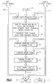
- Fig. 6 is a logic flow diagram of an alarm logic routine.
- a chiller 12 with sensors involved in the practice of the present invention, includes a compressor 13 which supplies high pressure refrigerant vapor over a fluid conduit 14 to a condenser 15. Liquid refrigerant flows from the condenser over a fluid conduit 16 to an expansion valve 17, the output of which is passed through a fluid conduit 18 to an evaporator 19, and thence the refrigerant vapor is passed through a fluid conduit 20 to the compressor 13.
- the valve 16 is controlled in response to a stepper motor or other valve control device 24 which in turn is controlled by a signal on a line 25 from a controller 26.
- the signal on the line 25 is based upon the superheat condition of the vapor in the conduit 20, which is calculated in a conventional way from the difference between the temperature at the outlet of the evaporator 19, as sensed by a temperature sensor 27, and the temperature of the refrigerant vapor at the inlet to the compressor 13, as sensed by a temperature sensor 28.
- the temperature of water at an outlet 31 of the evaporator 19, as sensed by a temperature sensor 32, is utilized in the controller 26 to turn the compressor on and off so as to maintain the water temperature setpoint.
- the pressure head across the condenser as determined by the difference between the condenser inlet pressure, sensed by a pressure detector 34, and the condenser outlet pressure, as sensed by a pressure detector 35, is utilized by the controller to provide a signal on a line 36 to turn a bank of fans 37 on or off, as is appropriate. All of the apparatus described thus far represents a conventional chiller, and it may be implemented and controlled in a conventional fashion.
- an accurate mathematical model of the chiller based on nonlinear algebraic and differential equations which describe the flow, pressure and temperature dynamics of the chiller, developed in a conventional way, can accurately characterize the compressor motor overheating condition, which the invention seeks to predict.
- the model may be similar to any of the following,
- the setup for obtaining the large number of samples uses a signal generator 42 which includes the pseudorandom binary sequence generators and drivers to produce U 1 -U 3 plus or minus one percent thereof, in response to the pseudorandom binary sequences. These are applied over signal lines 43 to a computer 44 having the high order thermodynamic model contained therein. The model, being excited by the inputs on the lines 43, produces values of X and Y (Table 1) for each successive input, which are provided over a suitable bus 45 to storage 46, along with the corresponding inputs, U.
- a signal generator 42 which includes the pseudorandom binary sequence generators and drivers to produce U 1 -U 3 plus or minus one percent thereof, in response to the pseudorandom binary sequences.
- the recursive, least-squares estimation routine can be found in
- the chiller of Fig. 1 is operated while an on-site, on-line computer 48 (generally not the computer of Figs. 2 and 3) monitors the inputs U 1 -U 3 and the outputs, Y 1 -Y 4 , on lines 49 and utilizes the Kalman filter technique to predict, for the sensed actual values of U and Y at a particular time of sampling, k, what the values of the outputs and the states should be at the next time of sampling, k+1.
- an on-site, on-line computer 48 (generally not the computer of Figs. 2 and 3) monitors the inputs U 1 -U 3 and the outputs, Y 1 -Y 4 , on lines 49 and utilizes the Kalman filter technique to predict, for the sensed actual values of U and Y at a particular time of sampling, k, what the values of the outputs and the states should be at the next time of sampling, k+1.
- the Kalman filter is itself updated prior to its use in filtering the chiller outputs so as to predict states and outputs.
- the sensed outputs are first used to update the Kalman filter equations and then the inputs and outputs are passed through the updated Kalman filter equations to compute predicted states (X) and outputs (Y).
- the state estimate is updated using: where is the filter state estimate at time k based on the measurements up to time k-1.
- the sampling, k may be separated by about three minutes.
- the updated Kalman gain matrix K is computed as: where P (.
- the state estimate Prior to taking the next measurement at k+1, the state estimate is propagated ahead in time one step using the state dynamics this is then used as in EQN. (1) of the next sampling.
- the Kalman filter At each sampling time, after the Kalman filter is updated, the known inputs, U, and measured sensor signals, Y, from the chiller are processed by the Kalman filter to generate optimal estimates of the chiller states, X and, and predictions of the sensor measurements, Y and. Subtracting Y and from the actual measurements, Y, forms the error signal vector, e, which is used to formulate a failure decision. For a Kalman filter, therefore, the error signal e(k) will be zero-mean, white, with covariance matrix.
- Fig. 5 The process carried out for each sampling period within the computer 48 during online monitoring is illustrated in Fig. 5.
- the monitoring system When the monitoring system is first put online, it will be initialized (block 51), including the initial state estimates and initial state estimate error covariance matrix as described hereinbefore.
- the state estimates are updated (block 52) as in Equation (3).
- the Kalman gain matrix is computed (block 53) and the state estimate error covariance matrix is updated and propagated to the next sampling time, as in Equations (4)-(6).
- the state estimate is propagated (block 54) to the next sampling time using state dynamics, as in Equation (7).
- the input sensor signals U1-U3 on lines 49 and the output sensor signals Y1-Y9 on lines 50 are applied to the Kalman filter (block 55).
- the Kalman filter generates optimal estimates of the chiller states, X and, and predictions of the sensor measurements, Y and.
- the prediction of the sensor measurements, Y and is compared against the actual current sensor measurement of Y, and the estimates of the chiller states, X and, is compared with the previous propagated estimates of the chiller states (block 56), to produce error signals.
- the error signals are compared with corresponding thresholds (block 57), which in this embodiment are taken to be ⁇ three standard deviations, and the exceedances are examined in an alarm logic routine (block 58) to determine if such exceedances are indicative of an impending compressor motor overtemperature condition, as set forth in Fig. 6.
- the logic routine of Fig. 6 is reached through an entry point 62 and tests 63-65 require that for an alarm condition to be recognized, there must be errors in the values of Y3, Y4 and Y5. If not, other programming is reached through a return point 66 without setting an alarm condition. If all three errors are present (Y3, Y4 and Y5), then a series of tests 67-70 determine if any one of X1, X3, X5 or X9 has an error. If so, an alarm condition may occur; but if none of these are in error, then the return point 66 is reached without setting an alarm condition.
- a series of tests 71-73 determine whether any one of X2, X4 or X7 is in error. If not, the return point is reached without setting an alarm condition. But, if all of Y3, Y4, Y5 are in error, any one of X1, X3, X5, or X9 is in error, and any one of X2, X4 and X7 is in error, then a step 74 sets the alarm condition.
- the alarm condition will cause a signal on a line 76 to actually activate an alarm 77 of any suitable sort and to cause a printer 78 to print out all the current input and output parameters on the lines 49 and 50 thereby to provide an indication of the nature of the impaired operation.
- the controller 26 and the parameters utilized to control the chiller 12 as expressed hereinbefore are exemplary merely; the chiller may be controlled in any desired way and the invention may be practiced simply by ensuring that the effect of the controller on the chiller is accurately reflected in the original, high order model. Similarly, the invention may be practiced in chillers having wide variety of variations with respect to the embodiment disclosed for exemplary purposes herein.
Landscapes
- Engineering & Computer Science (AREA)
- Physics & Mathematics (AREA)
- General Engineering & Computer Science (AREA)
- Artificial Intelligence (AREA)
- Evolutionary Computation (AREA)
- Mathematical Physics (AREA)
- General Physics & Mathematics (AREA)
- Automation & Control Theory (AREA)
- Mechanical Engineering (AREA)
- Thermal Sciences (AREA)
- Microelectronics & Electronic Packaging (AREA)
- Power Engineering (AREA)
- Air Conditioning Control Device (AREA)
- Testing And Monitoring For Control Systems (AREA)
- Feedback Control In General (AREA)
- Control Of Positive-Displacement Pumps (AREA)
- Devices That Are Associated With Refrigeration Equipment (AREA)
Applications Claiming Priority (2)
| Application Number | Priority Date | Filing Date | Title |
|---|---|---|---|
| US08/869,323 US5911127A (en) | 1997-06-05 | 1997-06-05 | Prediction of chiller compressor motor overheating |
| US869323 | 1997-06-05 |
Publications (2)
| Publication Number | Publication Date |
|---|---|
| EP0883046A1 true EP0883046A1 (de) | 1998-12-09 |
| EP0883046B1 EP0883046B1 (de) | 2002-06-26 |
Family
ID=25353342
Family Applications (1)
| Application Number | Title | Priority Date | Filing Date |
|---|---|---|---|
| EP98303678A Expired - Lifetime EP0883046B1 (de) | 1997-06-05 | 1998-05-11 | System zur Vorhersage der Überhitzung des Motors eines Kühlerverdichters |
Country Status (10)
| Country | Link |
|---|---|
| US (1) | US5911127A (de) |
| EP (1) | EP0883046B1 (de) |
| JP (1) | JP3029257B2 (de) |
| KR (1) | KR100291724B1 (de) |
| CN (1) | CN1098512C (de) |
| AR (1) | AR012935A1 (de) |
| AU (1) | AU733822B2 (de) |
| BR (1) | BR9801771B1 (de) |
| DE (1) | DE69806207T2 (de) |
| TW (1) | TW430720B (de) |
Cited By (7)
| Publication number | Priority date | Publication date | Assignee | Title |
|---|---|---|---|---|
| FR2793899A1 (fr) * | 1999-05-21 | 2000-11-24 | Baelz Gmbh Helmut | Procede et dispositif pour le controle du fonctionnement d'organes de reglage dans une installation thermique |
| WO2001001212A1 (en) * | 1999-06-23 | 2001-01-04 | Saab Ab | A method of supervising or controlling a device by means of a computer model |
| EP1465090A3 (de) * | 2000-12-22 | 2007-02-28 | American Standard International Inc. | Herstellungsverfahren mit elektronischem Austausch von Produktdaten |
| EP1731857A4 (de) * | 2004-01-21 | 2009-03-18 | Mitsubishi Electric Corp | Vorrichtungsdiagnosevorrichtung, gefrierzyklusvorrichtung, fluidkreislaufdiagnoseverfahren, vorrichtungsüberwachungssystem und gefrierzyklusüberwachungssystem |
| EP2000754A3 (de) * | 2007-06-04 | 2013-03-27 | RHOSS S.p.A. | Verfahren zur Schätzung der Wärmebelastung einer Leitung für eine Betriebsflüssigkeit am Auslass einer Kühlmaschine |
| EP3124897A1 (de) * | 2015-07-27 | 2017-02-01 | Honeywell spol s.r.o. | Verfahren und vorrichtung zur dampfkompressionsschaltkreissteuerung |
| EP3348925A1 (de) * | 2017-01-12 | 2018-07-18 | LG Electronics Inc. | Klimaanlagensystem und steuerungsverfahren |
Families Citing this family (34)
| Publication number | Priority date | Publication date | Assignee | Title |
|---|---|---|---|---|
| DE19818860C2 (de) * | 1998-04-28 | 2001-04-19 | Daimler Chrysler Ag | Verfahren und Einrichtung zur Detektion und Lokalisation von Sensorfehlern in Kraftfahrzeugen |
| EP0953815B1 (de) | 1998-04-30 | 2003-08-06 | Showa Denko K.K. | Anschlussvorrichtung für Wärmetauscher |
| US6651012B1 (en) * | 2001-05-24 | 2003-11-18 | Simmonds Precision Products, Inc. | Method and apparatus for trending and predicting the health of a component |
| BR0313132A (pt) * | 2002-07-31 | 2005-07-05 | Sydkraft Ab | Máquina elétrica |
| DE102004058621B4 (de) * | 2004-12-04 | 2008-08-07 | Audi Ag | Verfahren zum Ermitteln von Größen in einem Motorsteuergerät |
| DE102004058619A1 (de) * | 2004-12-04 | 2006-06-08 | Audi Ag | Diagnoseverfahren in Systemen |
| US7992395B2 (en) * | 2006-01-17 | 2011-08-09 | Hussmann Corporation | Expansion valve with piezo material |
| US8291720B2 (en) * | 2009-02-02 | 2012-10-23 | Optimum Energy, Llc | Sequencing of variable speed compressors in a chilled liquid cooling system for improved energy efficiency |
| US8532839B2 (en) | 2009-06-22 | 2013-09-10 | Johnson Controls Technology Company | Systems and methods for statistical control and fault detection in a building management system |
| US8600556B2 (en) | 2009-06-22 | 2013-12-03 | Johnson Controls Technology Company | Smart building manager |
| US9196009B2 (en) | 2009-06-22 | 2015-11-24 | Johnson Controls Technology Company | Systems and methods for detecting changes in energy usage in a building |
| US8788097B2 (en) * | 2009-06-22 | 2014-07-22 | Johnson Controls Technology Company | Systems and methods for using rule-based fault detection in a building management system |
| US9286582B2 (en) | 2009-06-22 | 2016-03-15 | Johnson Controls Technology Company | Systems and methods for detecting changes in energy usage in a building |
| US8731724B2 (en) | 2009-06-22 | 2014-05-20 | Johnson Controls Technology Company | Automated fault detection and diagnostics in a building management system |
| US8532808B2 (en) | 2009-06-22 | 2013-09-10 | Johnson Controls Technology Company | Systems and methods for measuring and verifying energy savings in buildings |
| US10739741B2 (en) | 2009-06-22 | 2020-08-11 | Johnson Controls Technology Company | Systems and methods for detecting changes in energy usage in a building |
| US9606520B2 (en) | 2009-06-22 | 2017-03-28 | Johnson Controls Technology Company | Automated fault detection and diagnostics in a building management system |
| US9753455B2 (en) | 2009-06-22 | 2017-09-05 | Johnson Controls Technology Company | Building management system with fault analysis |
| US11269303B2 (en) | 2009-06-22 | 2022-03-08 | Johnson Controls Technology Company | Systems and methods for detecting changes in energy usage in a building |
| US8165860B2 (en) * | 2009-08-25 | 2012-04-24 | Invensys Systems, Inc | Thermodynamic process control based on pseudo-density root for equation of state |
| US8386121B1 (en) | 2009-09-30 | 2013-02-26 | The United States Of America As Represented By The Administrator Of National Aeronautics And Space Administration | Optimized tuner selection for engine performance estimation |
| US10544801B2 (en) | 2009-10-21 | 2020-01-28 | Carrier Corporation | Centrifugal compressor part load control algorithm for improved performance |
| WO2011069700A2 (de) * | 2009-12-08 | 2011-06-16 | Siemens Aktiengesellschaft | Verfahren und vorrichtung zum regeln einer dampferzeugung in einer dampfkraftanlage |
| US9390388B2 (en) | 2012-05-31 | 2016-07-12 | Johnson Controls Technology Company | Systems and methods for measuring and verifying energy usage in a building |
| CN104654690B (zh) * | 2014-11-18 | 2017-01-11 | 深圳职业技术学院 | 冷水机组控制方法及控制系统 |
| US9778639B2 (en) | 2014-12-22 | 2017-10-03 | Johnson Controls Technology Company | Systems and methods for adaptively updating equipment models |
| WO2017085525A1 (en) * | 2015-11-19 | 2017-05-26 | Carrier Corporation | Diagnostics system for a chiller and method of evaluating performance of a chiller |
| US20170243413A1 (en) * | 2016-02-22 | 2017-08-24 | Hamilton Sundstrand Corporation | Method for determining aircraft sensor failure without a redundant sensor and correct sensor measurement when redundant aircraft sensors give inconsistent readings |
| WO2018146805A1 (ja) * | 2017-02-13 | 2018-08-16 | 三菱電機株式会社 | 冷凍装置 |
| JP7057205B2 (ja) * | 2018-05-01 | 2022-04-19 | 三菱重工業株式会社 | 油圧機器の異常診断方法、及び、油圧機器の異常診断システム |
| CN109827378B (zh) * | 2019-01-28 | 2021-08-03 | 长虹美菱股份有限公司 | 用于制冷设备变频压缩机运行失步的调控方法及装置 |
| DE102020118762A1 (de) | 2020-07-16 | 2022-01-20 | Vaillant Gmbh | Massenstromschätzung in linksdrehenden Kreisprozessen |
| EP4101666B1 (de) * | 2021-06-08 | 2025-04-02 | Wuhan Lotus Cars Co., Ltd. | Verfahren, steuermodul und system zur vermeidung einer überhitzung eines fahrzeuguntersystems |
| CN116398414B (zh) * | 2023-02-20 | 2025-09-23 | 北京华大智宝电子系统有限公司 | 一种空压机系统的监控报警方法和系统 |
Family Cites Families (5)
| Publication number | Priority date | Publication date | Assignee | Title |
|---|---|---|---|---|
| JPS5716719A (en) * | 1980-07-04 | 1982-01-28 | Hitachi Ltd | Method and equipment for controlling steam temperature in thermal power plant |
| US5394322A (en) * | 1990-07-16 | 1995-02-28 | The Foxboro Company | Self-tuning controller that extracts process model characteristics |
| FI922031A0 (fi) * | 1991-10-23 | 1992-05-05 | Antti Aarne Ilmari Lange | Foerfarande foer kalman-filter i stora system. |
| US5740033A (en) * | 1992-10-13 | 1998-04-14 | The Dow Chemical Company | Model predictive controller |
| US5633800A (en) * | 1992-10-21 | 1997-05-27 | General Electric Company | Integrated model-based reasoning/expert system diagnosis for rotating machinery |
-
1997
- 1997-06-05 US US08/869,323 patent/US5911127A/en not_active Expired - Lifetime
-
1998
- 1998-05-11 DE DE69806207T patent/DE69806207T2/de not_active Expired - Lifetime
- 1998-05-11 EP EP98303678A patent/EP0883046B1/de not_active Expired - Lifetime
- 1998-05-12 TW TW087107331A patent/TW430720B/zh not_active IP Right Cessation
- 1998-06-02 AU AU69871/98A patent/AU733822B2/en not_active Ceased
- 1998-06-04 BR BRPI9801771-3A patent/BR9801771B1/pt not_active IP Right Cessation
- 1998-06-05 AR ARP980102675A patent/AR012935A1/es unknown
- 1998-06-05 CN CN98109564A patent/CN1098512C/zh not_active Expired - Fee Related
- 1998-06-05 KR KR1019980020929A patent/KR100291724B1/ko not_active Expired - Fee Related
- 1998-06-05 JP JP10156954A patent/JP3029257B2/ja not_active Expired - Fee Related
Non-Patent Citations (2)
| Title |
|---|
| NADIRA R ET AL: "MODELING AND SIMULATION OF AN HVAC REFRIGERATION SYSTEM", PROCEEDINGS OF THE SCS SIMULATORS CONFERENCE, vol. 18, no. 4, 6 April 1987 (1987-04-06), USA, pages 175 - 181, XP002078880 * |
| USORO U ET AL: "AN INNOVATION BASED METHODOLOGY FOR HVAC SYSTEM FAULT DETECTION", TRANSACTIONS OF THE ASME, vol. 107, no. 4, December 1985 (1985-12-01), USA, pages 284 - 289, XP002078879 * |
Cited By (8)
| Publication number | Priority date | Publication date | Assignee | Title |
|---|---|---|---|---|
| FR2793899A1 (fr) * | 1999-05-21 | 2000-11-24 | Baelz Gmbh Helmut | Procede et dispositif pour le controle du fonctionnement d'organes de reglage dans une installation thermique |
| WO2001001212A1 (en) * | 1999-06-23 | 2001-01-04 | Saab Ab | A method of supervising or controlling a device by means of a computer model |
| EP1465090A3 (de) * | 2000-12-22 | 2007-02-28 | American Standard International Inc. | Herstellungsverfahren mit elektronischem Austausch von Produktdaten |
| EP1731857A4 (de) * | 2004-01-21 | 2009-03-18 | Mitsubishi Electric Corp | Vorrichtungsdiagnosevorrichtung, gefrierzyklusvorrichtung, fluidkreislaufdiagnoseverfahren, vorrichtungsüberwachungssystem und gefrierzyklusüberwachungssystem |
| US7558700B2 (en) | 2004-01-21 | 2009-07-07 | Mitsubishi Denki Kabushiki Kaisha | Equipment diagnosis device, refrigerating cycle apparatus, fluid circuit diagnosis method, equipment monitoring system, and refrigerating cycle monitoring system |
| EP2000754A3 (de) * | 2007-06-04 | 2013-03-27 | RHOSS S.p.A. | Verfahren zur Schätzung der Wärmebelastung einer Leitung für eine Betriebsflüssigkeit am Auslass einer Kühlmaschine |
| EP3124897A1 (de) * | 2015-07-27 | 2017-02-01 | Honeywell spol s.r.o. | Verfahren und vorrichtung zur dampfkompressionsschaltkreissteuerung |
| EP3348925A1 (de) * | 2017-01-12 | 2018-07-18 | LG Electronics Inc. | Klimaanlagensystem und steuerungsverfahren |
Also Published As
| Publication number | Publication date |
|---|---|
| CN1098512C (zh) | 2003-01-08 |
| TW430720B (en) | 2001-04-21 |
| KR19990006717A (ko) | 1999-01-25 |
| DE69806207D1 (de) | 2002-08-01 |
| DE69806207T2 (de) | 2002-11-07 |
| MX9804468A (es) | 1998-12-31 |
| CN1201959A (zh) | 1998-12-16 |
| AU733822B2 (en) | 2001-05-24 |
| BR9801771A (pt) | 1999-07-13 |
| KR100291724B1 (ko) | 2001-06-01 |
| EP0883046B1 (de) | 2002-06-26 |
| AU6987198A (en) | 1998-12-10 |
| JP3029257B2 (ja) | 2000-04-04 |
| JPH10339527A (ja) | 1998-12-22 |
| AR012935A1 (es) | 2000-11-22 |
| US5911127A (en) | 1999-06-08 |
| BR9801771B1 (pt) | 2009-08-11 |
Similar Documents
| Publication | Publication Date | Title |
|---|---|---|
| EP0883046B1 (de) | System zur Vorhersage der Überhitzung des Motors eines Kühlerverdichters | |
| US4410950A (en) | Method of and apparatus for monitoring performance of steam power plant | |
| US4755925A (en) | Plant diagnostic system | |
| KR100368703B1 (ko) | 팽창밸브모니터링시스템 | |
| EP1565720B1 (de) | Verfahren zur feststellung eines defektes in einem wärmetauscher | |
| JP3451554B1 (ja) | 異常検出方法、異常検出装置および温度調節器 | |
| US20060042277A1 (en) | Fault diagnostics and prognostics based on distance fault classifiers | |
| JP2002202242A (ja) | 技術的システムの老化による変化の検出方法,その装置,プログラム,記録媒体,検出システム,摩耗モデルの決定装置 | |
| Navarro-Esbri et al. | A vapour compression chiller fault detection technique based on adaptative algorithms. Application to on-line refrigerant leakage detection | |
| CA2344908A1 (en) | Model based fault detection and diagnosis methodology for hvac subsystems | |
| Beghi et al. | A data-driven approach for fault diagnosis in HVAC chiller systems | |
| US6101820A (en) | Method and device for diagnosing an air-conditioning loop of a motor vehicle | |
| JP2002147818A (ja) | 空気調和機およびその故障判定方法 | |
| JP2022052545A (ja) | 情報処理装置、情報処理方法、及びプログラム | |
| CN108351639B (zh) | 用于冷却器的诊断系统和评估冷却器性能的方法 | |
| JP4009288B2 (ja) | フラッシュガスを検出するための方法と装置 | |
| KR101549754B1 (ko) | 가변속 냉동시스템의 고장진단방법 | |
| CN110685904B (zh) | 一种螺杆机测试方法及系统 | |
| KR20120014685A (ko) | 히트펌프 시스템의 정상운전상태 감지장치 및 감지방법 | |
| MXPA98004468A (en) | Prediction of overheating of compressor motor enfria | |
| Zhang et al. | Fault detection and isolation of automotive air conditioning systems using first principle models | |
| JPH0493567A (ja) | 冷凍機の性能診断装置 | |
| Rueda et al. | Fault detection and diagnosis in liquid chillers | |
| RU2795112C1 (ru) | Способ контроля технического состояния компрессорно-конденсаторных агрегатов систем кондиционирования и устройство для его осуществления | |
| CN115264929B (zh) | 一种调频率调节方法、装置及空调 |
Legal Events
| Date | Code | Title | Description |
|---|---|---|---|
| PUAI | Public reference made under article 153(3) epc to a published international application that has entered the european phase |
Free format text: ORIGINAL CODE: 0009012 |
|
| AK | Designated contracting states |
Kind code of ref document: A1 Designated state(s): DE FR GB NL |
|
| AX | Request for extension of the european patent |
Free format text: AL;LT;LV;MK;RO;SI |
|
| 17P | Request for examination filed |
Effective date: 19990508 |
|
| AKX | Designation fees paid |
Free format text: DE FR GB NL |
|
| 17Q | First examination report despatched |
Effective date: 20001213 |
|
| GRAG | Despatch of communication of intention to grant |
Free format text: ORIGINAL CODE: EPIDOS AGRA |
|
| GRAG | Despatch of communication of intention to grant |
Free format text: ORIGINAL CODE: EPIDOS AGRA |
|
| GRAH | Despatch of communication of intention to grant a patent |
Free format text: ORIGINAL CODE: EPIDOS IGRA |
|
| GRAH | Despatch of communication of intention to grant a patent |
Free format text: ORIGINAL CODE: EPIDOS IGRA |
|
| GRAA | (expected) grant |
Free format text: ORIGINAL CODE: 0009210 |
|
| AK | Designated contracting states |
Kind code of ref document: B1 Designated state(s): DE FR GB NL |
|
| REG | Reference to a national code |
Ref country code: GB Ref legal event code: FG4D |
|
| REF | Corresponds to: |
Ref document number: 69806207 Country of ref document: DE Date of ref document: 20020801 |
|
| ET | Fr: translation filed | ||
| PLBE | No opposition filed within time limit |
Free format text: ORIGINAL CODE: 0009261 |
|
| STAA | Information on the status of an ep patent application or granted ep patent |
Free format text: STATUS: NO OPPOSITION FILED WITHIN TIME LIMIT |
|
| 26N | No opposition filed |
Effective date: 20030327 |
|
| PGFP | Annual fee paid to national office [announced via postgrant information from national office to epo] |
Ref country code: NL Payment date: 20080410 Year of fee payment: 11 |
|
| NLV4 | Nl: lapsed or anulled due to non-payment of the annual fee |
Effective date: 20091201 |
|
| PG25 | Lapsed in a contracting state [announced via postgrant information from national office to epo] |
Ref country code: NL Free format text: LAPSE BECAUSE OF NON-PAYMENT OF DUE FEES Effective date: 20091201 |
|
| REG | Reference to a national code |
Ref country code: FR Ref legal event code: ST Effective date: 20100129 |
|
| PG25 | Lapsed in a contracting state [announced via postgrant information from national office to epo] |
Ref country code: FR Free format text: LAPSE BECAUSE OF NON-PAYMENT OF DUE FEES Effective date: 20090602 |
|
| PGFP | Annual fee paid to national office [announced via postgrant information from national office to epo] |
Ref country code: FR Payment date: 20080424 Year of fee payment: 11 |
|
| PGFP | Annual fee paid to national office [announced via postgrant information from national office to epo] |
Ref country code: GB Payment date: 20160426 Year of fee payment: 19 Ref country code: DE Payment date: 20160421 Year of fee payment: 19 |
|
| REG | Reference to a national code |
Ref country code: DE Ref legal event code: R082 Ref document number: 69806207 Country of ref document: DE Representative=s name: SCHMITT-NILSON SCHRAUD WAIBEL WOHLFROM PATENTA, DE |
|
| REG | Reference to a national code |
Ref country code: DE Ref legal event code: R119 Ref document number: 69806207 Country of ref document: DE |
|
| GBPC | Gb: european patent ceased through non-payment of renewal fee |
Effective date: 20170511 |
|
| PG25 | Lapsed in a contracting state [announced via postgrant information from national office to epo] |
Ref country code: GB Free format text: LAPSE BECAUSE OF NON-PAYMENT OF DUE FEES Effective date: 20170511 Ref country code: DE Free format text: LAPSE BECAUSE OF NON-PAYMENT OF DUE FEES Effective date: 20171201 |