EP0883121B1 - Plattenspieler zur Wiedergabe von Minidisc und Compactdisc - Google Patents
Plattenspieler zur Wiedergabe von Minidisc und Compactdisc Download PDFInfo
- Publication number
- EP0883121B1 EP0883121B1 EP98304356A EP98304356A EP0883121B1 EP 0883121 B1 EP0883121 B1 EP 0883121B1 EP 98304356 A EP98304356 A EP 98304356A EP 98304356 A EP98304356 A EP 98304356A EP 0883121 B1 EP0883121 B1 EP 0883121B1
- Authority
- EP
- European Patent Office
- Prior art keywords
- roller
- disc
- loading
- minidisc
- storage medium
- Prior art date
- Legal status (The legal status is an assumption and is not a legal conclusion. Google has not performed a legal analysis and makes no representation as to the accuracy of the status listed.)
- Expired - Lifetime
Links
- 230000003287 optical effect Effects 0.000 claims description 3
- 230000005540 biological transmission Effects 0.000 description 14
- 238000010276 construction Methods 0.000 description 4
- 238000001514 detection method Methods 0.000 description 4
- 239000011347 resin Substances 0.000 description 2
- 229920005989 resin Polymers 0.000 description 2
- 238000000034 method Methods 0.000 description 1
Images



Classifications
-
- G—PHYSICS
- G11—INFORMATION STORAGE
- G11B—INFORMATION STORAGE BASED ON RELATIVE MOVEMENT BETWEEN RECORD CARRIER AND TRANSDUCER
- G11B17/00—Guiding record carriers not specifically of filamentary or web form, or of supports therefor
- G11B17/02—Details
- G11B17/04—Feeding or guiding single record carrier to or from transducer unit
- G11B17/057—Feeding or guiding single record carrier to or from transducer unit specially adapted for handling both discs contained within cartridges and discs not contained within cartridges
-
- G—PHYSICS
- G11—INFORMATION STORAGE
- G11B—INFORMATION STORAGE BASED ON RELATIVE MOVEMENT BETWEEN RECORD CARRIER AND TRANSDUCER
- G11B17/00—Guiding record carriers not specifically of filamentary or web form, or of supports therefor
- G11B17/02—Details
- G11B17/022—Positioning or locking of single discs
- G11B17/028—Positioning or locking of single discs of discs rotating during transducing operation
- G11B17/0282—Positioning or locking of single discs of discs rotating during transducing operation by means provided on the turntable
- G11B17/0283—Two or more turntables
-
- G—PHYSICS
- G11—INFORMATION STORAGE
- G11B—INFORMATION STORAGE BASED ON RELATIVE MOVEMENT BETWEEN RECORD CARRIER AND TRANSDUCER
- G11B17/00—Guiding record carriers not specifically of filamentary or web form, or of supports therefor
- G11B17/02—Details
- G11B17/04—Feeding or guiding single record carrier to or from transducer unit
- G11B17/0401—Details
- G11B17/0402—Servo control
- G11B17/0404—Servo control with parallel drive rollers
Definitions
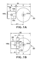
- a minidisc 100 and a compact disc 101 are arranged side by side on one and the same plane.
- Reference numeral 100a designates a center hole of the minidisc 100; 100b a shutter of the minidisc 100; 100c a housing of the minidisc; and 101a a center hole of the compact disc.
- the disc player for use in playback of both a minidisc and a compact disc to be mounted on vehicle cannot be mounted on a console box in almost all of vehicles unless they conform with the DIN Standard (West Germany Standard).
- DIN Standard West Germany Standard
- "1DIN size” set forth in the DIN Standard is 178 mm (width) x 53 mm (height) in front panel size, which is outside the "1DIN size” in the above-described arrangement. Therefore, the disc player corresponding to the DIN Standard cannot be prepared.
- the inventors of the present application have repeated their studies, and proposed the arrangement of the minidisc 100 and the compact disc 101 by making an optical pickup 103 for use in playback of both a minidisc and a compact disc the smallest dimension.
- the minidisc 100 and the compact disc 101 are arranged side by side on one and the same plane.
- the pickup 103 provided between the minidisc 100 and the compact disc 101 is miniaturized to the smallest limit whereby the center holes 100a and 101a of the minidisc 100 and the compact disc 101 are brought close to each other so that the distance L1 between the centers in FIG. 1A is changed to the distance L2 between the centers in FIG. 1B.
- dimension D2 is A + C - E, which indicates the dimension shortened by B + E from the dimension D1 (A + B + C) shown in FIG. 1A.
- D2 is the dimension of more or less 180 mm, which is however not within the "1DIN size".
- US-A-4,575,836 discusses a disc player capable of playing two types of disc, for which the player includes two turntables, and a mechanism for moving either of the turntables to a single predetermined play position. The movement is obtained by rotating a carrier or which the turntables are mounted about an axis which is not parallel to the axes of rotation of the turntables.
- the player further includes a reader or pick-up device which is separately mounted and positioned to read either type of disc brought to the predetermined play position.
- a purpose of the present invention is to provide a compact disc player for use in playback of both a minidisc and a compact disc.
- the present invention provides a disc player comprising: a first opening formed in a panel for loading a first disc storage medium with a first diameter; a second opening formed in the panel for loading a second disc storage medium with a second diameter longer than the first diameter, wherein central position of the first loading opening is displaced from a central position of the second loading opening; a chassis provided in an orthogonal direction with respect to the panel; a turning frame mounted on the chassis; a first rotary unit provided on the turning frame to rotate the first disc storage medium around a first axis; and a second rotary unit provided on the turning frame to rotate the second disc storage medium around a second axis; .
- the turning frame is turnable on said chassis about a third axis parallel to said first and second axes the player further comprising a rotary mechanism for turning the turning frame to move between at least a first reading position in which the position of the first rotary unit corresponds to a substantially central position with regard to the first loading opening, and a second reading position in which the position of the second rotary unit corresponds to a substantially central position with regard to the second loading opening.
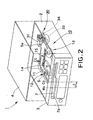
- the panel 3 is provided with a compact disc loading opening 7, and a minidisc loading opening 7a formed integral with a part of the compact disc loading opening 7.
- a central position Mo of the minidisc loading opening 7a is formed to be displaced by ⁇ from a central position Co of the compact disc loading opening 7.
- the floating chassis 5 is provided with a support 5a for supporting the mechanism unit 10 so that the unit 10 can be turned horizontally.
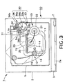
- FIG. 3 is a view taken by an arrow X in FIG. 2, showing the plane of disc player 1 with the upper cover 4 of FIG. 2 removed.
- the mechanism unit 10 is provided with a substantially rectangular-shaped turning frame 11; a rotary unit 12 for a minidisc, provided on the frame 11; a rotary unit 13 for a compact disc, provided opposite to the rotary unit 12; an optical pickup 14 for use in playback of both a minidisc and a compact disc, movable between the rotary units 12 and 13; and a feed mechanism 15 for driving the pickup 14.
- the turning frame 11 is provided with a hole 11a fitted into a support 5a of the floating chassis 5, and a cam groove 11b fitted into the rotary mechanism 30.
- the rotary unit 12 for a minidisc is provided with a motor 18 mounted on the turning frame 11, and a turntable 19 mounted on the motor 18.
- the rotary unit 13 for a compact disc is pruvided with a motor 21 mounted on the turning frame 11, and a turntable 22 mounted on the motor 21.
- the feed mechanism 15 is provided with a feed motor 23 mounted on the turning frame 11, and a feed screw 25 for moving the pickup 14 connected to the feed motor 23 through a group of gears 24.
- the rotary mechanism 30 is provided with a motor 31 mounted on the floating chassis 5, a cam gear 33 connected to the motor 31 through a group of gears 32, and a transmission lever 34 for transmitting the movement of the cam gear 33 to the turning frame 11.
- the cam gear 33 is provided with a gear 33a meshed with the group of gears 32, and a cam groove 33b fitted into the transmission lever 34.
- the transmission lever 34 is provided with a plate-like lever body 34a, a support 34b rotatably mounted on the floating chassis 5, a first pin 34c fitted into the cam groove 11b (as a cam follower), and a second pin 34d fitted into the cam groove 33b of the cam gear 33 (as a cam follower).
- the motor 31 is driven to rotate the cam gear 33 through the group of gears 32, the transmission lever 34 is rotated by the second pin 34d fitted into the cam groove 33b of the cam gear 33, and the turning frame 11 is horizontally turned by the first pin 34c of the transmission lever 34.
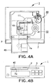
- FIGS. 4A and 4B illustrate the first operation of the disc player 1, showing a position of the mechanism unit 10 for reading or recording information of a minidisc 40.
- the position of the mechanism unit 10 for reading or recording information of the minidisc 40 is also the position of the mechanism unit 10 in the initial state.
- the minidisc 40 is detected by a detection switch not shown to maintain the initial state.
- the position of the minidisc 40 coincides with that of the turntable 19 in the lateral direction.
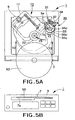
- FIGS. 5A and 5B illustrate the second operation of the disc player 1, showing a position of the mechanism unit 10 for reading information of a compact disc 50.
- the compact disc 50 When the compact disc 50 is loaded from the compact disc loading opening 7 as indicated by arrows Y2, the compact disc 50 is detected by a detection switch not shown.
- the motor 31 is driven to rotate the cam gear 33 through the group of gears 32 as indicated by an arrow Y3, and the transmission lever 34 is rotated as indicated by an arrow Y4 by the second pin 34d fitted into the cam groove 33b of the cam gear 33.
- the rotary frame 11 is rotated as indicated by an arrow Y5 about the support 5a of the floating chassis 5 by the first pin 34c of the transmission lever 34, and a read position on the compact disc 50 is moved to a substantially central position of the compact disc 50 loading opening 7. This achieves miniaturization of disc player 1 for use in playback of both a minidisc and a compact disc.
- the compact disc 50 is loaded from the inserting opening 7 and thereby subjected to centering onto the turntable 22 by a centering mechanism not shown.
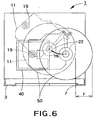
- FIG. 6 illustrates the third operation of the disc player 1, showing the comparison of the spacing between a case where the turning frame 11 is rotated to a predetermined position in order to read information on the compact disc 50 and another case where the turning frame 11 is not rotated.
- Positions of the turntable 22 and the compact disc 50 when the turning frame 11 has been rotated to the predetermined position are shown by the dash-dotted contour lines.
- a position of the turntable 22 when the turning frame 11 has not been rotated is shown by the broken lines, and a position of the compact disc 50 when the turning frame 11 has not been rotated is shown by the solid line.
- FIG. 7 shows an external appearance of a disc player 1a also for use in playback and/or recording of both a minidisc (MD, a first disc storage medium) and a compact disc (CD, a second disc storage medium with a diameter longer than that of the first disc storage medium) accord-ing to the present invention.
- MD minidisc
- CD compact disc
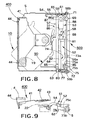
- clamp unit 400 and the loading mechanism 500 are explained with reference to FIGS. 8, 9 and 10.
- the clamp unit 400 is provided with a clamp holder 41 rotatably (within a specific angle) attached at its one end to the floating chassis 5; a flat spring 42 attached to the other end of the clamp holder 41; a clamper 43 rotatably attached to the flat spring 42; extension springs 44 bridged over the upper cover 4 and the clamp holder 41; and an actuator (not shown) for actuating the clamp holder 41.
- the loading mechanism 500 is provided with a first roller unit 51 rotatably attached to the floating chassis 5; a second roller unit 52 rotatably attached to the first roller unit 51; an actuator 53 for rotating the roller units 51 and 52; a rotary lever (level adjuster) connected to the first roller unit 51; and a minidisc holder 90 located close to the turntable 19 from the second roller unit 52.
- the first roller frame 56 is provided with intermediate gears 59 and 61 linked to the transmission shaft 58 and a reversal spring 62 bridged over the first roller frame 56 and the floating chassis 5.
- the first roller frame 56 is formed with a hole 56a for connection to the second roller unit 52.
- Supporters 56b support the first roller frame 56 as rotatably attached to the floating chassis 5.
- the first roller 57 is provided with a roller shaft 63; a long rubber roller 64 with a concave middle portion rotatably attached to one end of the roller shaft 63; a free roller 65 rotatably attached to the rubber roller 64 at one end thereof, with a slightly larger diameter than that of an end portion of the rubber roller 64; and a final gear 66 attached to the other end of the roller shaft 63.
- the first roller 57 is long enough to transfer a large compact disc with a diameter of 12 cm.
- the second roller unit 52 is located inside the first roller frame 56.
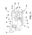
- the second roller unit 52 is provided with a second roller frame 73 rotatably attached to the shaft 68 via collar (not shown); a second roller 74 rotatably provided between left and right side plates of the second roller frame 73; and a hinge lever 75 for leaping up the second roller frame 73.
- the second roller 74 is short enough to transfer an MD cartridge and provided as parallel to the first roller 57 within a lateral length thereof.
- the second roller frame 73 has an intermediate gear 77 linked to the transmission shaft 58 via the transmission gear 72.
- a protrusion 73a is fitted into the hole 56a of the first roller frame 56.
- the hinge lever 75 is fitted in a groove 73b.
- the second roller 74 is provided with a roller shaft 79; a resin roller 81 attached to the roller shaft 79; a rubber roller 82 by which the resin roller 81 is partially covered from an end thereof; and a final gear 83 attached to an end of the roller shaft 79 at rubber roller side.
- the hinge lever 75 is provided with a shaft 75a rotatably attached to the first roller frame 56; a lever 75b operated by loading an MD cartridge; and an operating portion 75c for leaping up the second roller frame 73.
- the actuator 53 is provided with a motor 86 attached to the floating chassis 5; a worm gear 87 attached to a shaft 86a of the motor 86; and a link gear 88 engaged with the worm gear 87.
- the link gear 88 is further engaged with the drive gear 69.
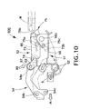
- the loading mechanism 500 is explained with reference to FIG. 10.
- the rotary lever 54 is provided with a U-groove 54a in which the roller shaft 63 is fitted; a pivot 54b rotatably attached to the floating chassis 5; and a drive pin 54c fitted in an actuator (not shown).
- the supporters 56b for rotatably supporting the first roller frame 56 and the shaft 68 for rotatably supporting the second roller frame 73 are arranged coaxially.
- FIG. 11 depicts the second roller frame 73 rotatably attached to the transmission shaft 58 via collar (not shown) and the protrusion 73a fitted in the hole 56a.
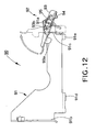
- the minidisc holder 90 is explained with reference to FIG. 12.
- the holder 91 is provided with a supporting shaft 91a of the shutter operating unit 92; side guides 91b and 91c for guiding side faces of an MD cartridge; and front guides 91d and 91e for smooth loading of the MD cartridge.
- the shutter operating unit 92 is provided with an operating holder 93 rotatably (within a predetermined range) attached to the supporting shaft 91a; a shutter operating spring 94 attached to the operating holder 93; and a torsion spring 95 bridged over the holder 91 and the operating holder 93.
- the operating holder 93 has a lock release 93a for an MD cartridge and a hole 93b for accepting the supporting shaft 91a.
- FIG. 13B illustrates a state in that the mechanism unit 10 is positioned where the MD cartridge M can be loaded into the disc player 1a.
- FIG. 13B further illustrates a state in that lateral positions of the MD cartridge M and the turntable 19 meet each other by restriction of lateral position of the MD cartridge M through the minidisc loading opening 7a with respect to the front panel 3 as described in the first embodiment.
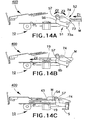
- a second operation of the loading mechanism 500 is explained with reference to FIGS. 14A to 14C.
- FIG. 14A illustrates a state in that loading of the MD cartridge M in a direction indicated by an arrow Z1 operates the hinge lever 75 (FIG. 11) to leap up the second roller unit 52 to push the first roller unit 51 upward with the protrusion 73a of the second roller unit 52.
- the first and second rollers 57 and 74 always rotate in opposite directions due to difference in construction such that the first roller unit 51 has the two intermediate gears 59 and 61, whereas the second roller unit 52 only one intermediate gear 77 as shown in FIG. 8.
- FIG. 14B illustrates a state in that the second roller 74 touches the upper surface of the MD cartridge M to transfer the MD cartridge M in a direction of the turntable 19.
- the MD cartridge M is further transferred in a direction indicated by an arrow Z4 while pushing the second roller 74 upward.
- the first roller 57 rotates in the opposite direction with respect to the second roller 74.
- the transfer of the MD cartridge M is free from the existence of the first roller 57 due to the construction in that the first roller 57 has a free roller 65 touching the upper surface of the MD cartridge M.
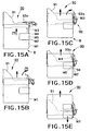
- FIG. 15A illustrates a state in that loading the MD cartridge M into the holder 91 in a direction indicated by an arrow Z5 makes one end of the housing M1 touch the lock release 93a.
- FIG. 15C illustrates a state in that still further loading of the MD cartridge M into the holder 91 makes the shutter operating unit 92 became parallel to a direction in which the MD cartridge M has been loaded, the lock release 93a being fitted in the shutter release groove M3.
- the present invention achieves the loading mechanism 50 compact in a depth direction by means of the rotatable shutter operating unit 92 that is pushed upward by the MD cartridge M in use, whereas set at a waiting position while not being used.
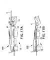
- FIG. 16A illustrates a state in that the compact disc C can be loaded into the disc player 1a through the compact disc loading opening 7.
Landscapes
- Feeding And Guiding Record Carriers (AREA)
- Holding Or Fastening Of Disk On Rotational Shaft (AREA)
Claims (4)
- Disc-Abspielgerät, umfassend:wobei der Drehrahmen auf dem Chassis um eine dritte Achse parallel zu der ersten und der zweiten Achse drehbar ist;eine erste Öffnung (7A), die in einer Platte (3) ausgebildet ist, zum Einschieben eines ersten scheibenartigen Speichermediums mit einem ersten Durchmesser;eine zweite Öffnung (7), die in der Platte ausgebildet ist, zum Einschieben eines zweiten scheibenartigen Speichermediums mit einem zweiten Durchmesser, der größer als der erste Durchmesser ist;ein Chassis (5), das sich in senkrechter Richtung in Bezug auf die Platte erstreckt;einen Drehrahmen (11), der auf dem Chassis montiert ist;eine erste Dreheinheit (12), die an dem Drehrahmen vorgesehen ist, um das erste scheibenartige Speichermedium um eine erste Achse zu drehen; undeine zweite Dreheinheit (13), die an dem Drehrahmen vorgesehen ist, um das zweite scheibenartige Speichermedium um eine zweite Achse zu drehen;
wobei das Abspielgerät ferner einen Drehmechanismus (10) umfasst, um der Drehrahmen derart zu drehen, dass er sich zumindest zwischen einer ersten Leseposition, in welcher die Stellung der ersten Dreheinheit einer im Wesentlichen mittigen Position in Bezug auf die erste Einschuböffnung entspricht, und einer zweiten Leseposition, in welcher die Stellung der zweiten Dreheinheit einer im Wesentlichen mittigen Position in Bezug auf die zweite Einschuböffnung entspricht, bewegt;
wobei die mittige Position der ersten Einschuböffnung zu der mittigen Position der zweiten Einschuböffnung seitlich versetzt ist, und zwar in einer Richtung senkrecht zu der ersten, zweiten und dritten Achse. - Disc-Abspielgerät nach Anspruch 1,
das ferner einen optischen Abnehmer umfasst, der zwischen der ersten und der zweiten Dreheinheit bewegbar ist, um Informationen auf dem ersten und dem zweiten scheibenartigen Speichermedium zu lesen. - Disc-Abspielgerät nach Anspruch 1,
wobei das erste scheibenartige Speichermedium eine Minidisc ist und das zweite scheibenartige Speichermedium eine Compactdisc ist. - Disc-Abspielgerät nach Anspruch 1,
das ferner einen Lademechanismus (500) zum Laden des ersten und des zweiten scheibenartigen Speichermediums auf die erste bzw. die zweite Dreheinheit aufweist,
wobei der Lademechanismus umfasst:eine erste Rolle (57) zum Transferieren des zweiten scheibenartigen Speichermediums,eine zweite Rolle (74) zum Transferieren des ersten scheibenartigen Speichermediums, wobei die zweite Rolle parallel zu der ersten Rolle vorgesehen ist und der größte Teil der zweiten Rolle innerhalb der seitlichen Ausdehnung der ersten Rolle liegt;einen Halter zum Halten des ersten scheibenartigen Speichermediums, wobei der Halter von der zweiten Rolle aus dicht an dem ersten Drehtisch vorgesehen ist; undeine Betätigungseinrichtung, um die erste und die zweite Rolle zu bewegen.
Applications Claiming Priority (3)
| Application Number | Priority Date | Filing Date | Title |
|---|---|---|---|
| JP14672697 | 1997-06-04 | ||
| JP14672697A JP3424227B2 (ja) | 1997-06-04 | 1997-06-04 | ミニディスク及びコンパクトディスクの兼用ディスクプレーヤ |
| JP146726/97 | 1997-06-04 |
Publications (3)
| Publication Number | Publication Date |
|---|---|
| EP0883121A2 EP0883121A2 (de) | 1998-12-09 |
| EP0883121A3 EP0883121A3 (de) | 1999-01-27 |
| EP0883121B1 true EP0883121B1 (de) | 2004-08-18 |
Family
ID=15414190
Family Applications (1)
| Application Number | Title | Priority Date | Filing Date |
|---|---|---|---|
| EP98304356A Expired - Lifetime EP0883121B1 (de) | 1997-06-04 | 1998-06-02 | Plattenspieler zur Wiedergabe von Minidisc und Compactdisc |
Country Status (5)
| Country | Link |
|---|---|
| US (1) | US6009062A (de) |
| EP (1) | EP0883121B1 (de) |
| JP (1) | JP3424227B2 (de) |
| CN (1) | CN1113346C (de) |
| DE (1) | DE69825673T2 (de) |
Families Citing this family (16)
| Publication number | Priority date | Publication date | Assignee | Title |
|---|---|---|---|---|
| US6262961B1 (en) * | 1997-11-18 | 2001-07-17 | Matsushita Electric Industrial Co., Ltd. | Disk loading device and disk cartridge |
| KR100277960B1 (ko) * | 1997-12-04 | 2001-01-15 | 윤종용 | 광 디스크 로딩장치 |
| US6388974B1 (en) * | 1998-10-07 | 2002-05-14 | Alpine Electronics, Inc. | Recording medium driving apparatus |
| US6504808B2 (en) | 1998-10-08 | 2003-01-07 | Pioneer Corporation | Front-loading disk player with separate first and second carrier units |
| JP3822760B2 (ja) | 1999-01-29 | 2006-09-20 | パイオニア株式会社 | カートリッジ搬送装置 |
| JP2000222804A (ja) * | 1999-01-29 | 2000-08-11 | Pioneer Electronic Corp | カートリッジ搬送装置 |
| WO2000048183A1 (fr) * | 1999-02-12 | 2000-08-17 | Mitsubishi Denki Kabushiki Kaisha | Unite de disque |
| WO2000070611A1 (fr) * | 1999-05-14 | 2000-11-23 | Mitsubishi Denki Kabushiki Kaisha | Appareil a disque |
| EP1073049B1 (de) * | 1999-07-30 | 2004-10-06 | Sanyo Electric Co., Ltd. | Plattenlaufwerk |
| JP3512694B2 (ja) * | 1999-12-27 | 2004-03-31 | Necパーソナルプロダクツ株式会社 | 光ディスク媒体用ローディング装置 |
| JP2003059154A (ja) | 2001-08-21 | 2003-02-28 | Tanashin Denki Co | ディスク再生機の再生基板固定装置 |
| US7161887B2 (en) * | 2001-11-13 | 2007-01-09 | Digeo, Inc. | Method and apparatus for extracting digital data from a medium |
| JP2004030857A (ja) * | 2002-06-28 | 2004-01-29 | Pioneer Electronic Corp | ディスクガイド構造 |
| JP2005158153A (ja) * | 2003-11-26 | 2005-06-16 | Matsushita Electric Ind Co Ltd | フィードローラと光ディスク搬送装置と光ディスク記録再生装置 |
| US7895612B2 (en) * | 2004-12-13 | 2011-02-22 | Panasonic Corporation | Disk loading device having positioning and detection levers that move entirely outside an outermost circumference of an area occupied by a disk mounted therein |
| JP5771014B2 (ja) * | 2011-01-27 | 2015-08-26 | アルパイン株式会社 | ディスク装置 |
Family Cites Families (7)
| Publication number | Priority date | Publication date | Assignee | Title |
|---|---|---|---|---|
| JPS60106280U (ja) * | 1983-12-22 | 1985-07-19 | パイオニア株式会社 | デイスクプレ−ヤ |
| EP0212500B1 (de) * | 1985-08-10 | 1990-06-13 | Sanyo Electric Co., Ltd. | Frontladevorrichtung für Plattengerät |
| US5197056A (en) * | 1989-07-04 | 1993-03-23 | U.S. Philips Corporation | Disc record player |
| US5383716A (en) * | 1993-09-16 | 1995-01-24 | S.A.F.E.-Q.R. Corporation | Quick-release bicycle axle fastener |
| KR960005407B1 (ko) * | 1993-12-13 | 1996-04-24 | 대우전자주식회사 | 미니디스크겸용 콤팩트디스크플레이어 |
| KR960009844B1 (en) * | 1994-01-19 | 1996-07-24 | Daewoo Electronics Co Ltd | Mini and cd player |
| JPH09167419A (ja) * | 1995-12-15 | 1997-06-24 | Fujitsu Ltd | 光ディスク装置 |
-
1997
- 1997-06-04 JP JP14672697A patent/JP3424227B2/ja not_active Expired - Fee Related
-
1998
- 1998-06-02 DE DE1998625673 patent/DE69825673T2/de not_active Expired - Lifetime
- 1998-06-02 EP EP98304356A patent/EP0883121B1/de not_active Expired - Lifetime
- 1998-06-04 CN CN98102921A patent/CN1113346C/zh not_active Expired - Fee Related
- 1998-06-04 US US09/090,254 patent/US6009062A/en not_active Expired - Fee Related
Also Published As
| Publication number | Publication date |
|---|---|
| US6009062A (en) | 1999-12-28 |
| JPH10340512A (ja) | 1998-12-22 |
| EP0883121A2 (de) | 1998-12-09 |
| CN1204840A (zh) | 1999-01-13 |
| EP0883121A3 (de) | 1999-01-27 |
| DE69825673T2 (de) | 2005-01-13 |
| CN1113346C (zh) | 2003-07-02 |
| DE69825673D1 (de) | 2004-09-23 |
| JP3424227B2 (ja) | 2003-07-07 |
Similar Documents
| Publication | Publication Date | Title |
|---|---|---|
| US6009062A (en) | Disc player for minidisc and compact disc playback | |
| KR100433415B1 (ko) | 디스크 플레이어의 디스크 로딩장치 | |
| EP1308948B1 (de) | Plattenwechselvorrichtung | |
| GB2229851A (en) | Centering mechanism for automotive disk player | |
| JP4125115B2 (ja) | ディスク装置 | |
| JPH0341659A (ja) | ディスク駆動装置 | |
| CN100339904C (zh) | 盘盒 | |
| CA2484524C (en) | Disc cartridge | |
| JP3971205B2 (ja) | ディスク挿入位置決め装置 | |
| JP3424638B2 (ja) | ミニディスク及びコンパクトディスクの兼用ディスクプレーヤ | |
| JP3725322B2 (ja) | ディスク装置 | |
| US5933404A (en) | Disc changer | |
| EP0517402B1 (de) | Plattenwechsler | |
| JP3424636B2 (ja) | ミニディスク及びコンパクトディスクの兼用ディスクプレーヤ | |
| KR100598117B1 (ko) | 디스크 이격장치 및 디스크 이격방법 | |
| JP3852774B2 (ja) | ミニディスク及びコンパクトディスクの兼用ディスクプレーヤ | |
| JPH117689A (ja) | ディスク装置 | |
| JP2979789B2 (ja) | ディスクカートリッジ排出機構 | |
| JP3227370B2 (ja) | カートリッジ誤挿入防止装置 | |
| JP2003217261A (ja) | ミニディスク及びコンパクトディスクの兼用ディスクプレーヤ | |
| JP3424229B2 (ja) | ミニディスク及びコンパクトディスクの兼用ディスクプレーヤ | |
| KR0174640B1 (ko) | 멀티 미니 디스크 구동장치 및 방법 | |
| JP2003217260A (ja) | 兼用メディアプレーヤ | |
| JP3180561B2 (ja) | ディスク装置 | |
| KR0142308B1 (ko) | 디스크 플레이어 |
Legal Events
| Date | Code | Title | Description |
|---|---|---|---|
| PUAI | Public reference made under article 153(3) epc to a published international application that has entered the european phase |
Free format text: ORIGINAL CODE: 0009012 |
|
| AK | Designated contracting states |
Kind code of ref document: A2 Designated state(s): DE FR GB |
|
| AX | Request for extension of the european patent |
Free format text: AL;LT;LV;MK;RO;SI |
|
| PUAL | Search report despatched |
Free format text: ORIGINAL CODE: 0009013 |
|
| AK | Designated contracting states |
Kind code of ref document: A3 Designated state(s): AT BE CH CY DE DK ES FI FR GB GR IE IT LI LU MC NL PT SE |
|
| AX | Request for extension of the european patent |
Free format text: AL;LT;LV;MK;RO;SI |
|
| 17P | Request for examination filed |
Effective date: 19990105 |
|
| AKX | Designation fees paid |
Free format text: DE FR GB |
|
| 17Q | First examination report despatched |
Effective date: 20020604 |
|
| GRAP | Despatch of communication of intention to grant a patent |
Free format text: ORIGINAL CODE: EPIDOSNIGR1 |
|
| GRAS | Grant fee paid |
Free format text: ORIGINAL CODE: EPIDOSNIGR3 |
|
| GRAA | (expected) grant |
Free format text: ORIGINAL CODE: 0009210 |
|
| AK | Designated contracting states |
Kind code of ref document: B1 Designated state(s): DE FR GB |
|
| REG | Reference to a national code |
Ref country code: GB Ref legal event code: FG4D |
|
| REF | Corresponds to: |
Ref document number: 69825673 Country of ref document: DE Date of ref document: 20040923 Kind code of ref document: P |
|
| ET | Fr: translation filed | ||
| PLBE | No opposition filed within time limit |
Free format text: ORIGINAL CODE: 0009261 |
|
| STAA | Information on the status of an ep patent application or granted ep patent |
Free format text: STATUS: NO OPPOSITION FILED WITHIN TIME LIMIT |
|
| 26N | No opposition filed |
Effective date: 20050519 |
|
| PGFP | Annual fee paid to national office [announced via postgrant information from national office to epo] |
Ref country code: FR Payment date: 20100709 Year of fee payment: 13 |
|
| PGFP | Annual fee paid to national office [announced via postgrant information from national office to epo] |
Ref country code: GB Payment date: 20100602 Year of fee payment: 13 Ref country code: DE Payment date: 20100526 Year of fee payment: 13 |
|
| GBPC | Gb: european patent ceased through non-payment of renewal fee |
Effective date: 20110602 |
|
| REG | Reference to a national code |
Ref country code: FR Ref legal event code: ST Effective date: 20120229 |
|
| REG | Reference to a national code |
Ref country code: DE Ref legal event code: R119 Ref document number: 69825673 Country of ref document: DE Effective date: 20120103 |
|
| PG25 | Lapsed in a contracting state [announced via postgrant information from national office to epo] |
Ref country code: DE Free format text: LAPSE BECAUSE OF NON-PAYMENT OF DUE FEES Effective date: 20120103 Ref country code: FR Free format text: LAPSE BECAUSE OF NON-PAYMENT OF DUE FEES Effective date: 20110630 |
|
| PG25 | Lapsed in a contracting state [announced via postgrant information from national office to epo] |
Ref country code: GB Free format text: LAPSE BECAUSE OF NON-PAYMENT OF DUE FEES Effective date: 20110602 |