EP0883232A1 - Méthode et appareil pour le démarrage d'un moteur électrique - Google Patents
Méthode et appareil pour le démarrage d'un moteur électrique Download PDFInfo
- Publication number
- EP0883232A1 EP0883232A1 EP98304439A EP98304439A EP0883232A1 EP 0883232 A1 EP0883232 A1 EP 0883232A1 EP 98304439 A EP98304439 A EP 98304439A EP 98304439 A EP98304439 A EP 98304439A EP 0883232 A1 EP0883232 A1 EP 0883232A1
- Authority
- EP
- European Patent Office
- Prior art keywords
- time
- starting
- electric motor
- thyristor
- sum
- Prior art date
- Legal status (The legal status is an assumption and is not a legal conclusion. Google has not performed a legal analysis and makes no representation as to the accuracy of the status listed.)
- Withdrawn
Links
- 238000000034 method Methods 0.000 title claims abstract description 35
- 230000003247 decreasing effect Effects 0.000 claims description 2
- 230000002411 adverse Effects 0.000 description 4
- 230000007704 transition Effects 0.000 description 4
- 238000004804 winding Methods 0.000 description 3
- 239000004020 conductor Substances 0.000 description 2
- 238000010586 diagram Methods 0.000 description 2
- 230000006698 induction Effects 0.000 description 2
- 238000009434 installation Methods 0.000 description 2
- 230000035939 shock Effects 0.000 description 2
- 230000007812 deficiency Effects 0.000 description 1
- 230000000694 effects Effects 0.000 description 1
- 230000005611 electricity Effects 0.000 description 1
- 239000004065 semiconductor Substances 0.000 description 1
Images

Classifications
-
- H—ELECTRICITY
- H02—GENERATION; CONVERSION OR DISTRIBUTION OF ELECTRIC POWER
- H02P—CONTROL OR REGULATION OF ELECTRIC MOTORS, ELECTRIC GENERATORS OR DYNAMO-ELECTRIC CONVERTERS; CONTROLLING TRANSFORMERS, REACTORS OR CHOKE COILS
- H02P1/00—Arrangements for starting electric motors or dynamo-electric converters
- H02P1/16—Arrangements for starting electric motors or dynamo-electric converters for starting dynamo-electric motors or dynamo-electric converters
- H02P1/26—Arrangements for starting electric motors or dynamo-electric converters for starting dynamo-electric motors or dynamo-electric converters for starting an individual polyphase induction motor
- H02P1/28—Arrangements for starting electric motors or dynamo-electric converters for starting dynamo-electric motors or dynamo-electric converters for starting an individual polyphase induction motor by progressive increase of voltage applied to primary circuit of motor
Definitions
- the present invention relates to a method of and an apparatus for starting an AC electric motor.
- a method of starting an AC electric motor comprises a step of starting an AC electric motor by applying a full voltage to said AC electric motor in a stop state on the unit of a positive or negative half-wave through a repetition of an ON time of a multiple of integer thereof and an OFF time subsequent thereto; and a step of gradually increasing a ratio of the ON time to a sum of the ON time and the OFF time as the time elapses substantially from by a fraction of a certain number up to "1" during the starting process.
- the sum of the ON time and the OFF time subsequent thereto may be set constant, and the ratio of the ON time to the sum of the ON time and the OFF time may also be so controlled as to increase substantially proportionally to the time.
- the ratio of the ON time to the sum of the ON time and the OFF time per period may be changed exponetial-function-wise in accordance with the passage of time.
- the OFF time per period may be set substantially constant, and the ON time may also be so controlled as to gradually increase with the passage of time.
- the ON time per period may be set substantially constant, and the OFF time per period may also be so controlled as to gradually decrease in accordance with the passage of time.
- an apparatus for starting an AC electric motor comprises a thyristor connected in series between an AC power supply and said AC electric motor, a starting time setting unit for setting a starting time of the AC electric motor, a starting pattern setting unit for setting a pattern for a time of an effective applying voltage applied to the AC electric motor when started, and a thyristor control unit for starting the AC electric motor by applying a full voltage from the AC power supply to the AC electric motor in a stop state on the unit of a positive or negative half-wave through a repetition of an ON time of a multiple of integer thereof and an OFF time subsequent thereto in accordance with contents of settings by the starting time setting unit and the starting pattern setting unit, and controlling the thyristor so that a ratio of the ON time to a sum of the ON time and the OFF time as the time elapses substantially from by a fraction of a certain number up to "1" during the starting process.
- FIG. 1 shows one embodiment of the present invention.
- An AC electric motor 2 to be started is connected to AC power supply terminals R, S, T via a thyristor unit 4 basically constructed as a module.
- electromagnetic contactors 5, 6 are connected protectively respectively to a power supply side and a load side of the thyristor unit 4, and further there is provided an electromagnetic contactor 7 for bridging between the thyristor unit 4 and the electromagnetic contactors 5, 6.
- the thyristor unit 4 is, in this embodiment, connected in series to only a U-phase and a W-phase, and is constructed of a U-phase thyristor unit 4u and a W-phase thyristor unit 4w.
- a V-phase is composed of a short-circuit conductor 4s.
- a thyristor unit 4v (unillustrated) may also be provided in place of this short-circuit conductor 4s.
- the thyristors are, however, provided only to the two phases (U and W phases), whereby such a predetermined purpose as switching ON/OFF the current can be accomplished. Therefore, the thyristors are not necessarily provided to all the three phases in terms of costs thereof.
- Each of the thyristors 4u, 4w is constructed of a pair of thyristors that are in an antiparallel connection, and gate terminals a, b are led out of each thyristor of the U-phase thyristor unit 4u, while gate terminals c, d are led out of each thyristor of the W-phase thyristor unit 4w.
- a soft-start control circuit 10 is provided in order to soft-start the AC electric motor 2 trough the thyristor unit 4.
- the soft-start control circuit 10 is constructed of a starting time setting unit 11, a starting pattern setting unit 12 and a thyristor control circuit 13.
- the starting time setting unit 11 sets a starting time, one case being that a starting time is predicted and set based on a power supply system configuration, various characteristics of the AC electric motor 2 and a characteristic of a mechanical load connected to the AC electric motor 2, and the other case being that the starting time is empirically set based on test data.
- the starting pattern setting unit 12 sets which effective voltage pattern to start the electric motor from an onset of the starting process to a completion thereof during the starting time set by the starting time setting unit 11.
- the thyristor control circuit 13 controls an ON-time and an OFF-time of each thyristor of the thyristor unit 4 in order to attain the desired starting in accordance with contents of the settings by the starting pattern setting unit 12 as well as by the starting time setting unit 11.
- the soft start control circuit 10 obtains control electric power through the electromagnetic contactor 8 from the power supply terminals R, T.
- the electromagnetic contactor 8 may or may not interlock with the ON/OFF operations of the electromagnetic contactor 5.
- an ignition phase angle of the thyristor is not controlled in a positive or negative half-wave of the power supply voltage, and the ON-time and the OFF-time which will be mentioned later on are, on the unit of the positive or negative half-wave of the voltage, set to a multiple of integer thereof at all times.
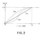
- a ratio of the ON-time to a sum of an ON-time at a certain timing and an OFF-time subsequent thereto, is referred to as a "duty" , and, as shown in FIG.
- the starting pattern setting unit 12 selects and sets an optimal starting pattern each time in consideration of a state of the power supply and a load characteristic as well.
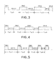
- FIG. 3 is a time chart showing the ON/OFF operation of the thyristor unit 4, corresponding to the linear characteristic pattern P1.
- the duties in the respective periods are ON1/Tp1 ⁇ ON2/Tp2 ⁇ ON3/Tp3 ⁇ ..., and gradually increase with the elapse of time.
- Initial values and increase widths of each individual period and of the ON time are determined taking a relationship with the starting time Ts into consideration.
- the OFF times OFF1, OFF2, OFF3, ... are OFF1 > OFF2 > OFF3 > ... reversely to the case of the ON times.
- the figures are shown conception-wise but may not necessarily properly be shown in mathematics. When an individual period value calculated based on the starting time and on the starting pattern becomes less than a half-cycle, the figure is rounded off on the half-cycle unit such as the half-adjusting method. In short, it may suffice to roughly meet the starting pattern shown in FIG. 2.
- the duty in each period gradually increases with the passage of time such as ON1/Tp1 ⁇ ON2/Tp2 ⁇ ON3/Tp3 ⁇ ...
- the periods change such as Tp1 ⁇ Tp2 ⁇ Tp3 ⁇ ...
- the relationship between the ON times becomes ON1 ⁇ ON2 ⁇ ON3...
- the initial values and the increase widths of the ON time and of the OFF time are determined considering the relationship with the starting time Ts.
- the starting pattern in this case is approximate to the starting pattern P2 in FIG. 2.
- the electromagnetic contactors 5, 6, 8 are set in the ON-state, and the starting time is set by the starting time setting unit 11. Then, the starting pattern setting unit 12 selects and sets the starting pattern. At this time, the electromagnetic contactor 7 remains OFF. Thereafter, the thyristor control circuit 13 launches into the soft start.
- the thyristor control circuit 13 controls the ON/OFF processes of the thyristor 4 in order to attain a desired starting characteristic in accordance with the contents of the settings by the starting time setting unit 11 and the starting pattern setting unit 12.
- the thyristor is ignited when given an ignition signal from the thyristor control circuit 13, and a full voltage thereof is applied from the AC power supply to the AC electric motor 2.
- the OFF operation of the thyristor is carried out by imparting no ignition signal to the thyristor from the thyristor control circuit 13, and the thyristor is automatically brought into the OFF state at a terminal point (a point of 360 degrees in the case of the negative half-wave and a point of 180 degrees in the case of the positive half-wave) of the half-wave with the ignition signal disappeared.
- the full voltage is thus applied to the AC electric motor 2.
- the duty is small, and hence it never happens that the above-described inconvenience occurs with the so-called full voltage starting.
- the electricity is not necessarily supplied to the electric motor 2 via the thyristor unit 4.
- the thyristor unit 4 may also be kept waiting till the electric motor is started next time by switching ON the electromagnetic contactor 7 for bypassing the thyristor unit 4 while switching OFF the electromagnetic contactors 5, 6 as the necessity may arise.
- the AC electric motor 2 is as described above soft-started, thereby making it feasible to relieve adverse influences upon the outside appliance due to the drop of the voltage when the so-called full voltage starting is effected and upon the electric motor and the mechanical load due to the voltage shock as well as making it possible to easily set the starting pattern taking into consideration the load torque and time durable quantities of the electric motor and of the starting apparatus.
- the complicated phase control of the thvristor is not executed, and therefore the costs for the equipments can be restrained.
- the present invention provides a method whereby an AC electric motor is started by applying a full voltage from an AC power supply to the AC electric motor in a stop state on the unit of a positive or negative half-wave through a repetition of an ON time of a multiple of integer thereof and an OFF time subsequent thereto, and a ratio of the ON time to a sum of the ON time and the OFF time is gradually increased as the time elapses from by a factor of a certain number up to "1" during the starting process.
Landscapes
- Engineering & Computer Science (AREA)
- Power Engineering (AREA)
- Motor And Converter Starters (AREA)
- Control Of Ac Motors In General (AREA)
Applications Claiming Priority (2)
| Application Number | Priority Date | Filing Date | Title |
|---|---|---|---|
| JP147912/97 | 1997-06-05 | ||
| JP9147912A JPH10337063A (ja) | 1997-06-05 | 1997-06-05 | 交流電動機の始動方法及び装置 |
Publications (1)
| Publication Number | Publication Date |
|---|---|
| EP0883232A1 true EP0883232A1 (fr) | 1998-12-09 |
Family
ID=15440924
Family Applications (1)
| Application Number | Title | Priority Date | Filing Date |
|---|---|---|---|
| EP98304439A Withdrawn EP0883232A1 (fr) | 1997-06-05 | 1998-06-04 | Méthode et appareil pour le démarrage d'un moteur électrique |
Country Status (6)
| Country | Link |
|---|---|
| EP (1) | EP0883232A1 (fr) |
| JP (1) | JPH10337063A (fr) |
| KR (1) | KR19990006552A (fr) |
| CN (1) | CN1068731C (fr) |
| AU (1) | AU6993098A (fr) |
| TW (1) | TW370738B (fr) |
Cited By (7)
| Publication number | Priority date | Publication date | Assignee | Title |
|---|---|---|---|---|
| WO2001089072A3 (fr) * | 2000-05-19 | 2002-03-28 | Eaton Corp | Procede pour controler le demarrage d"un moteur a induction c.a. utilisant une commande alpha en boucle fermee |
| RU2197056C2 (ru) * | 2000-12-06 | 2003-01-20 | ОАО "Богословский алюминиевый завод" | Устройство для управления электродвигателем вибратора |
| RU2220496C2 (ru) * | 2001-11-08 | 2003-12-27 | Открытое акционерное общество "Сибирско-Уральская алюминиевая компания" | Устройство для централизованного управления группой электродвигателей вибраторов |
| AU2001253263B2 (en) * | 2000-04-14 | 2005-05-26 | The Western States Machine Company | Centrifuge motor control |
| RU2263389C1 (ru) * | 2004-02-24 | 2005-10-27 | Открытое акционерное общество "Сибирско-Уральская алюминиевая компания" | Устройство для централизованного управления группой электродвигателей-вибраторов |
| WO2006067093A1 (fr) * | 2004-12-22 | 2006-06-29 | Siemens Aktiengesellschaft | Procede pour commander une charge de courant triphase et circuit pour realiser ce procede |
| EP1511165A3 (fr) * | 2003-08-29 | 2007-10-10 | Rockwell Automation Technologies, Inc. | Démarreur polyphasique à tension réduite avec un relais à dérivation, une isolation électrique entre les phases et une masse de dissipation thermique commune |
Families Citing this family (10)
| Publication number | Priority date | Publication date | Assignee | Title |
|---|---|---|---|---|
| US6163129A (en) * | 1999-03-11 | 2000-12-19 | Eaton Corporation | Method of controlling the starting, stopping and speed of an AC induction motor |
| KR100383072B1 (ko) * | 2000-11-03 | 2003-05-09 | 삼화이오씨알 주식회사 | 스타-델타 접촉기 |
| CN100369373C (zh) * | 2006-04-29 | 2008-02-13 | 冯德义 | 全压电机起动控制电路 |
| CN1889354A (zh) * | 2006-07-26 | 2007-01-03 | 辽宁荣信电力电子股份有限公司 | 跳波式有级变频无级调压电机软起动方法 |
| NO20075383A (no) * | 2007-10-22 | 2008-10-13 | In Motion As | Regulering av tyngre maskiner |
| CN105186932A (zh) * | 2014-05-26 | 2015-12-23 | 珠海格力电器股份有限公司 | 一种直流电机启动转速控制方法 |
| CN104378008A (zh) * | 2014-12-10 | 2015-02-25 | 苏州艾克威尔科技有限公司 | 软启动器及具有其的空气压缩机 |
| EP3758214B2 (fr) * | 2019-06-25 | 2025-07-16 | Siemens Aktiengesellschaft | Démarreur de moteur et procédé de démarrage d'un moteur électrique |
| CN113904303B (zh) * | 2020-06-22 | 2024-04-16 | 浙江大元泵业股份有限公司 | 一种水泵电机保护器的控制算法及水泵电机保护器 |
| CN112383246A (zh) * | 2020-11-30 | 2021-02-19 | 湖北万征电气有限公司 | 一种经济型高压固态软起动柜 |
Citations (3)
| Publication number | Priority date | Publication date | Assignee | Title |
|---|---|---|---|---|
| JPS60194788A (ja) * | 1984-03-13 | 1985-10-03 | M Syst Giken:Kk | 交流電動機の電源装置 |
| DE4130532A1 (de) * | 1991-09-13 | 1993-03-18 | Fraunhofer Ges Forschung | Verfahren und vorrichtung zur drehzahl- und/oder leistungsaufnahme-regulierung eines elektromotors |
| US5650697A (en) * | 1994-12-07 | 1997-07-22 | Mitsubishi Denki Kabushiki Kaisha | Motor unit, motor drive unit, fan unit and method of controlling the motor drive unit |
-
1997
- 1997-06-05 JP JP9147912A patent/JPH10337063A/ja active Pending
-
1998
- 1998-06-01 KR KR1019980020210A patent/KR19990006552A/ko not_active Withdrawn
- 1998-06-03 TW TW087108755A patent/TW370738B/zh active
- 1998-06-04 AU AU69930/98A patent/AU6993098A/en not_active Abandoned
- 1998-06-04 EP EP98304439A patent/EP0883232A1/fr not_active Withdrawn
- 1998-06-05 CN CN98109579A patent/CN1068731C/zh not_active Expired - Fee Related
Patent Citations (3)
| Publication number | Priority date | Publication date | Assignee | Title |
|---|---|---|---|---|
| JPS60194788A (ja) * | 1984-03-13 | 1985-10-03 | M Syst Giken:Kk | 交流電動機の電源装置 |
| DE4130532A1 (de) * | 1991-09-13 | 1993-03-18 | Fraunhofer Ges Forschung | Verfahren und vorrichtung zur drehzahl- und/oder leistungsaufnahme-regulierung eines elektromotors |
| US5650697A (en) * | 1994-12-07 | 1997-07-22 | Mitsubishi Denki Kabushiki Kaisha | Motor unit, motor drive unit, fan unit and method of controlling the motor drive unit |
Non-Patent Citations (2)
| Title |
|---|
| BERGHAENEL D: "SCHWINGUNSPAKETSTEUERUNG ZUR LEISTUNGSREGULIERUNG ELEKTRISCHER MASCHINEN", RADIO FERNSEHEN ELEKTRONIK, vol. 33, no. 6, June 1984 (1984-06-01), pages 389 - 391, XP002073017 * |
| PATENT ABSTRACTS OF JAPAN vol. 010, no. 039 (E - 381) 15 February 1986 (1986-02-15) * |
Cited By (7)
| Publication number | Priority date | Publication date | Assignee | Title |
|---|---|---|---|---|
| AU2001253263B2 (en) * | 2000-04-14 | 2005-05-26 | The Western States Machine Company | Centrifuge motor control |
| WO2001089072A3 (fr) * | 2000-05-19 | 2002-03-28 | Eaton Corp | Procede pour controler le demarrage d"un moteur a induction c.a. utilisant une commande alpha en boucle fermee |
| RU2197056C2 (ru) * | 2000-12-06 | 2003-01-20 | ОАО "Богословский алюминиевый завод" | Устройство для управления электродвигателем вибратора |
| RU2220496C2 (ru) * | 2001-11-08 | 2003-12-27 | Открытое акционерное общество "Сибирско-Уральская алюминиевая компания" | Устройство для централизованного управления группой электродвигателей вибраторов |
| EP1511165A3 (fr) * | 2003-08-29 | 2007-10-10 | Rockwell Automation Technologies, Inc. | Démarreur polyphasique à tension réduite avec un relais à dérivation, une isolation électrique entre les phases et une masse de dissipation thermique commune |
| RU2263389C1 (ru) * | 2004-02-24 | 2005-10-27 | Открытое акционерное общество "Сибирско-Уральская алюминиевая компания" | Устройство для централизованного управления группой электродвигателей-вибраторов |
| WO2006067093A1 (fr) * | 2004-12-22 | 2006-06-29 | Siemens Aktiengesellschaft | Procede pour commander une charge de courant triphase et circuit pour realiser ce procede |
Also Published As
| Publication number | Publication date |
|---|---|
| JPH10337063A (ja) | 1998-12-18 |
| CN1068731C (zh) | 2001-07-18 |
| CN1202035A (zh) | 1998-12-16 |
| TW370738B (en) | 1999-09-21 |
| HK1016359A1 (en) | 1999-10-29 |
| AU6993098A (en) | 1998-12-10 |
| KR19990006552A (ko) | 1999-01-25 |
Similar Documents
| Publication | Publication Date | Title |
|---|---|---|
| EP0883232A1 (fr) | Méthode et appareil pour le démarrage d'un moteur électrique | |
| KR100397565B1 (ko) | 다기능 하이브리드 개폐기 | |
| KR100238770B1 (ko) | 바이패스 콘택터를 갖는 전기모우터제어기 | |
| EP0547243B1 (fr) | Procede et appareil de commande et d'entrainement pour moteur asynchrone | |
| US5760567A (en) | Induced voltage reduction method and an induced voltage reduction apparatus for an induction motor | |
| JP2011087399A (ja) | 電動機の巻線切替え装置 | |
| JPH10187256A (ja) | 交流電力制御装置 | |
| US7414377B2 (en) | System and method for automatic current limit control | |
| US9780699B2 (en) | Motor protection relay and method for starting motor of motor protection relay | |
| KR20230119923A (ko) | 모터 구동 장치 및 그 제어 방법 | |
| US20150300305A1 (en) | Motor starter | |
| KR100492757B1 (ko) | 하이브리드 모터 스타터의 기동 제어회로 | |
| US6509703B1 (en) | Method and system for reduced voltage start-up of AC motors in multi-motor system | |
| JP7554127B2 (ja) | 交流発電機 | |
| KR100438984B1 (ko) | 인버터의 출력 전류 제한 회로 | |
| JP2000116164A (ja) | 誘導電動機のスターデルタ起動装置 | |
| KR100234044B1 (ko) | 모터 구동 교대운전 제어 장치 | |
| KR200354196Y1 (ko) | 전동기 구동 장치 | |
| JP2003309989A (ja) | 電動機の起動装置とその起動方法 | |
| JPH07203695A (ja) | 主電動機のスター・デルタ始動装置 | |
| JP4208480B2 (ja) | 直流電源装置 | |
| KR20040076378A (ko) | 하이브리드 모터 스타터의 정지 제어회로 | |
| JP2002171777A (ja) | 三相誘導電動機のスターデルタ始動装置及び同機のスターデルタ始動法 | |
| SU1226598A1 (ru) | Способ торможени асинхронного электродвигател | |
| JP2986423B2 (ja) | 電圧制御装置 |
Legal Events
| Date | Code | Title | Description |
|---|---|---|---|
| PUAI | Public reference made under article 153(3) epc to a published international application that has entered the european phase |
Free format text: ORIGINAL CODE: 0009012 |
|
| AK | Designated contracting states |
Kind code of ref document: A1 Designated state(s): DE FR GB IT |
|
| AX | Request for extension of the european patent |
Free format text: AL;LT;LV;MK;RO;SI |
|
| 17P | Request for examination filed |
Effective date: 19981217 |
|
| AKX | Designation fees paid |
Free format text: DE FR GB IT |
|
| 17Q | First examination report despatched |
Effective date: 20010710 |
|
| STAA | Information on the status of an ep patent application or granted ep patent |
Free format text: STATUS: THE APPLICATION IS DEEMED TO BE WITHDRAWN |
|
| 18D | Application deemed to be withdrawn |
Effective date: 20011121 |