EP0883280B1 - Abbildungssystem mit beweglichem Ausrichtstift - Google Patents
Abbildungssystem mit beweglichem Ausrichtstift Download PDFInfo
- Publication number
- EP0883280B1 EP0883280B1 EP98110170A EP98110170A EP0883280B1 EP 0883280 B1 EP0883280 B1 EP 0883280B1 EP 98110170 A EP98110170 A EP 98110170A EP 98110170 A EP98110170 A EP 98110170A EP 0883280 B1 EP0883280 B1 EP 0883280B1
- Authority
- EP
- European Patent Office
- Prior art keywords
- registration device
- registration
- medium
- movement
- bar
- Prior art date
- Legal status (The legal status is an assumption and is not a legal conclusion. Google has not performed a legal analysis and makes no representation as to the accuracy of the status listed.)
- Expired - Lifetime
Links
- 238000003384 imaging method Methods 0.000 title claims abstract description 81
- 230000007246 mechanism Effects 0.000 claims abstract description 18
- 230000003287 optical effect Effects 0.000 claims description 11
- 238000001514 detection method Methods 0.000 claims description 9
- 238000000034 method Methods 0.000 claims description 6
- 230000000452 restraining effect Effects 0.000 claims 2
- 230000000903 blocking effect Effects 0.000 claims 1
- 239000004020 conductor Substances 0.000 claims 1
- 239000000463 material Substances 0.000 description 2
- 230000008569 process Effects 0.000 description 2
- 230000009471 action Effects 0.000 description 1
- 229910052782 aluminium Inorganic materials 0.000 description 1
- XAGFODPZIPBFFR-UHFFFAOYSA-N aluminium Chemical compound [Al] XAGFODPZIPBFFR-UHFFFAOYSA-N 0.000 description 1
- 230000000712 assembly Effects 0.000 description 1
- 238000000429 assembly Methods 0.000 description 1
- 238000000576 coating method Methods 0.000 description 1
- 229910052751 metal Inorganic materials 0.000 description 1
- 239000002184 metal Substances 0.000 description 1
- 239000007769 metal material Substances 0.000 description 1
- 230000004048 modification Effects 0.000 description 1
- 238000012986 modification Methods 0.000 description 1
- 229920006254 polymer film Polymers 0.000 description 1
- 230000036316 preload Effects 0.000 description 1
Images


Classifications
-
- H—ELECTRICITY
- H04—ELECTRIC COMMUNICATION TECHNIQUE
- H04N—PICTORIAL COMMUNICATION, e.g. TELEVISION
- H04N1/00—Scanning, transmission or reproduction of documents or the like, e.g. facsimile transmission; Details thereof
- H04N1/04—Scanning arrangements, i.e. arrangements for the displacement of active reading or reproducing elements relative to the original or reproducing medium, or vice versa
- H04N1/06—Scanning arrangements, i.e. arrangements for the displacement of active reading or reproducing elements relative to the original or reproducing medium, or vice versa using cylindrical picture-bearing surfaces, i.e. scanning a main-scanning line substantially perpendicular to the axis and lying in a curved cylindrical surface
- H04N1/08—Mechanisms for mounting or holding the sheet around the drum
- H04N1/083—Holding means
- H04N1/0869—Holding means capable of holding different sized sheets
-
- H—ELECTRICITY
- H04—ELECTRIC COMMUNICATION TECHNIQUE
- H04N—PICTORIAL COMMUNICATION, e.g. TELEVISION
- H04N1/00—Scanning, transmission or reproduction of documents or the like, e.g. facsimile transmission; Details thereof
- H04N1/04—Scanning arrangements, i.e. arrangements for the displacement of active reading or reproducing elements relative to the original or reproducing medium, or vice versa
- H04N1/06—Scanning arrangements, i.e. arrangements for the displacement of active reading or reproducing elements relative to the original or reproducing medium, or vice versa using cylindrical picture-bearing surfaces, i.e. scanning a main-scanning line substantially perpendicular to the axis and lying in a curved cylindrical surface
- H04N1/08—Mechanisms for mounting or holding the sheet around the drum
- H04N1/083—Holding means
- H04N1/0873—Holding means for holding the sheet on the internal surface of the drum
-
- H—ELECTRICITY
- H04—ELECTRIC COMMUNICATION TECHNIQUE
- H04N—PICTORIAL COMMUNICATION, e.g. TELEVISION
- H04N1/00—Scanning, transmission or reproduction of documents or the like, e.g. facsimile transmission; Details thereof
- H04N1/04—Scanning arrangements, i.e. arrangements for the displacement of active reading or reproducing elements relative to the original or reproducing medium, or vice versa
- H04N1/06—Scanning arrangements, i.e. arrangements for the displacement of active reading or reproducing elements relative to the original or reproducing medium, or vice versa using cylindrical picture-bearing surfaces, i.e. scanning a main-scanning line substantially perpendicular to the axis and lying in a curved cylindrical surface
- H04N1/08—Mechanisms for mounting or holding the sheet around the drum
- H04N1/0882—Registering or guiding means other than the holding means
-
- H—ELECTRICITY
- H04—ELECTRIC COMMUNICATION TECHNIQUE
- H04N—PICTORIAL COMMUNICATION, e.g. TELEVISION
- H04N1/00—Scanning, transmission or reproduction of documents or the like, e.g. facsimile transmission; Details thereof
- H04N1/04—Scanning arrangements, i.e. arrangements for the displacement of active reading or reproducing elements relative to the original or reproducing medium, or vice versa
- H04N1/06—Scanning arrangements, i.e. arrangements for the displacement of active reading or reproducing elements relative to the original or reproducing medium, or vice versa using cylindrical picture-bearing surfaces, i.e. scanning a main-scanning line substantially perpendicular to the axis and lying in a curved cylindrical surface
- H04N1/0607—Scanning a concave surface, e.g. with internal drum type scanners
Definitions
- the present invention relates to imaging systems such as platesetters and imagesetters and more particularly to imaging systems with moveable registration pins. Even more it relates to an imaging system according to the preamble of claim 1 and a corresponding method for positioning image media.
- Modem imagesetters and platesetters utilize optical scanners to write or record images for subsequent reproduction or to read a prerecorded image at a predefined resolution rate.
- Such scanners may write or record images on or read prerecorded images from various media including photo or thermal sensitive paper or polymer films, photo or thermal sensitive coatings or erasable imaging materials, an aluminum or other metal base printing plate, or other type media.
- the medium is typically mounted on an imaging surface which may be planar or curved and then scanned with an optical beam.
- the primary components of modern imagesetting and platesetting systems include an image processor to generate and/or edit an image, a raster image processor (RIP) for converting data signals from the image processor into signals which can be understood by a controller which controls the imaging by the imagesetter or platesetter.
- RIP raster image processor
- the imagesetter or platesetter itself typically includes an imaging head such as a scan assembly which is often disposed and movable within a drum cylinder in which the recording or recorded medium is mounted.
- the controller in accordance with the signals from the RIP and its own programmed instructions, generates signals to control the optical scanning so as to write images on or read images from the medium mounted within the drum cylinder by scanning one or more optical beams over the inside circumference of the drum cylinder while the cylinder itself remains fixed.
- a typical scan assembly of a cylindrical drum type imager system may include a spin mirror or other optical device to direct the light beam over the inside circumference of the drum cylinder, as will be well understood by one skilled in the art.
- the medium to be imaged be properly positioned on the support surface of the imaging system.
- registration pins, punches or notches are utilized for this purpose.
- the applicable registration devices are fixedly mounted along the medium support surface such that, when the medium is loaded into the imaging system it is positioned against the registration devices.
- the medium being loaded onto the support surface prior to imaging is properly positioned by forcing the medium to be imaged against the registration devices.
- the medium may contact less than all the registration devices and therefore be skewed on the support surface at the time of imaging.
- an imaging system such as an imagesetter or platesetter, is provided for imaging media of differing widths.
- the media may be metallic or non-metallic, i.e. may or may not be electrically conductive.
- the system includes a loading device for moving the medium to be imaged, leading edge first, along a planar or curved medium support surface, e.g. an internal surface of a cylindrical drum, to a desired imaging position.
- the leading edge of the medium extends across the medium width and substantially perpendicular to the direction of movement of the medium during loading.
- One or more registration devices for example a pin(s).
- a drive mechanism is provided to move the registration device(s) so as to be positioned to correspond to the width of the medium to be imaged.
- the imaging system can thereby properly position media of differing widths on the imaging support surface.
- the drive mechanism preferably moves the registration device(s) substantially parallel to the longitudinal axis of the cylindrical drum to appropriate locations to ensure contact with the leading edge of the medium to be loaded.
- a guide mechanism is connected to each registration device to guide its movement in the direction of movement of the medium as it is pushed by the leading edge of the medium. That is, when the leading edge of the medium contacts each registration device during loading, it applies a force to move the registration device in the same direction as the medium.
- a registration bar is provided to restrain the movement of each registration device once it reaches a point of contact with the registration bar. This ensures proper alignment registration of the medium as it is loaded onto the imaging support surface.
- the registration device(s) each have a contact surface of making contact with a contact surface of the registration bar.
- the drive mechanism contacts the contact surface of the registration bar to thereby provide a fixed relative positioning of each registration device and the registration bar.
- multiple registration devices are provided.
- each is beneficially positioned proximate to a respective end of the leading edge of the medium being loaded.
- the positioning is generally set as desired for the particular implementation as will be understood by those skilled in the art.
- One of the registration devices may be fixed.
- the leading edge of the medium will typically contact both registration devices during loading.
- the imaging will begin at a predefined distance from the registration devices and parallel to the registration bar.
- the applicable guide mechanism will guide the movement of one registration device until it too moves to a point of contact with the registration bar.
- the movement of the other registration device, guided by its guide mechanism will continue until it too moves to a point of contact with the registration bar.
- one registration device may continue its movement after the other registration device has contacted the registration bar.
- the medium is also squared or deskewed as it is loaded onto the imaging support surface.
- a detection circuit connected to an electrical power source, is beneficially connected each registration device. Another connection is made at the registration bar. When the registration device contacts the registration bar the detection circuit is closed allowing a current to flow and thereby providing a clear indication of the proper alignment of the applicable registration device with the registration bar.
- an optical emitter such as an light emitting diode (LED)
- LED light emitting diode
- an optical detector for example a photodetector such as a photodiode, detects the radiating beam passing between the applicable registration device and the registration bar.
- the registration device contacts the registration bar the radiating beam is blocked and therefore undetectable by the optical detector. Accordingly, a clear indication of proper alignment of the medium is provided even if the registration device andlor registration bar are formed of material which is not electrically conductive.
- Figure 1 depicts an imaging system in accordance with the present invention.
- the imaging system includes a computer 2 which may be a personal computer, a workstation, or virtually any type of computing device and may form part of an operator control panel.
- the computer 2 allows images to be created or edited and serves as a general input device.
- the computer 2 can be utilized to select a particular scanning resolution to be used in imaging during a particular operational sequence.
- the imaging system further includes a stacked plate handler 4 which is controlled by the handler controller 7.
- the stacked plate handler 4 stores media 10 of various sizes in different cassettes, as will be described further below.
- the computer 2 can be utilized by the system operator to input commands identifying the desired plate size. The computer 2 will then generate a signal, responsive to which the handler controller 7 controls the handler 4 such that plates from the applicable cassette within the handler 4 are made accessible to a plate picker 5.
- the plate picker 5 removes a plate from the handler 4 and conveys the plate to the loading device or applicator 50 of the scan engine 12 which is controlled by engine controller 6.
- Images are transmitted from the computer 2 to the raster image processor (RIP) 3 which converts the digitized signals received from the computer 2 into signals which can be understood by the engine controller 6 which controls the scan engine 12.
- the scan engine 12 includes the plate picker 5 which operates in conjunction with the stacked plate handler 4 and the applicator 50 to move individual plates from the handler 4 to the applicator 50 for loading.
- the scan engine 12 includes a registration pins 18 or 18' and registration bar 24 or 24' which are utilized to properly position the medium on the support surface 22 of the cylindrical drum 20 during loading.
- the image is recorded by scanning the light beam parallel to the registration bar 24 or 24'. Recorded media is then transferred to the media processor 9 which is controlled by the processor controller 8 in accordance with signals received from the RIP 3 to develop or otherwise process the imaged plate. The processed plate is then removed from the system.
- a subsequent operation may include mounting the plate onto a plate notcher.
- the notcher may include registration means for registering the leading edge of the plate and transferring the leading edge registration by notching the plate for subsequent mounting onto a press.
- the plate may be mounted directly onto a press cylinder using the leading edge of the plate for registration.
- registration means would be located at substantially the same positions as the registration pins of the imaging system. These registration means could be similar to the registration pins 18 or 18' and registration bar 24 or 24'.
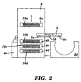
- FIG 2 provides a more detailed depiction of the handler 4 and individual media cassettes 4a-d.
- the handler 4 also includes slip sheet remover 4e for removing slip sheets between plates stacked within each cassette.
- the cassettes are movable vertically to position a desired cassette below the plate picker 5 to provide a plate of a selected size.
- the plate picker 5 using suction devices 5a-5c, lifts the plate from the handler cassette 4b, as shown, and then conveys the individual plate to the applicator 50 of Figure 1 for loading into the cylindrical drum 20.
- each of the cassettes 4a-4d stores a different sized plate.
- the plates in the respective cassettes have different widths.
- the width is intended to refer to the dimension which, when the plate is loaded onto the support surface of the internal drum, is measured in a direction parallel to the longitudinal axis of the drum, as will be discussed in more detail below.
- the system operator can identify a desired plate size using the computer 2 by, for example, selecting one of multiple plate sizes displayed on a monitor of the computer 2, or inputting a desired plate size or cassette number representing the cassette in which plates of the desired size are stored, to generate a signal to the RIP 3.
- the signal is transformed by the RIP 3 into an appropriate signal to the handler controller 7.
- the controller 7 controls the handler 4 in the manner previously described such that plates of the desired size can be conveyed by the plate picker 5 to the applicator 50 of the engine 12.
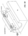
- Figure 3A depicts the cylindrical drum 20 with a sheet of medium 10' loaded therein.
- the medium 10' has a width W measured parallel to the longitudinal axis X-X of the cylindrical drum 20.
- the medium 10' is loaded such that the leading edge 10a of the medium 10' contacts the registration pins 18 or 18' which, as will be detailed further below, are thereby moved into contact with the registration bar 24 or 24'.
- the medium is left justified at a desired position either against a registration pin 19 or using an edge detector assembly 19'. If left edge registration pin 19 is utilized, it may be preferable to fix the left side registration pin 18 or 18' with respect to the registration bar 24 or 24'.
- an edge detector 19' is used, as shown in Figure 3B, it will be preferable to have both registration pins 18 and 18' adjustable.
- the left edge detector 19' is a large area light detector which is recessed in the drum 20.
- the detector 19' detects light from the scanning light beam over the portion of the detector now covered by the plate.
- the detector 19' generates a signal representing the location of the edge of the plate on the detector.
- the signal is transmitted to the controller 6 which, on the basis of the identified location of the side edge of the plate, begins the imaging a predefined number of scan lines from the edge.
- a drive assembly 26 attaches the registration pin 18 or 18' to the registration bar 24 or 24'.
- the drive assembly moves the registration pins 18 or 18' parallel with the axis X-X of the cylindrical drum 20 to adjust the positioning of the registration pins 18 or 18' on the registration bar 24 or 24' in accordance with the plate size identified on the computer 2. Accordingly, as indicated by the two-headed arrows at each of the drive assemblies 26, each drive assembly 26 can be moved further towards or away from the respective ends of the registration bar 24 or 24', depending upon the selected plate size, to move each of the pins 18 or 18' to a position corresponding to the width of the plate to be imaged.
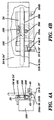
- Figures 4A and 4B detail the movement assembly 26.
- Figure 4A depicts a side view of the movement assembly.
- the assembly includes a stepper motor 100 which drives a gear 200.
- the gear 200 engages a rack 300 to drive the assembly 26 along the registration bar 24 or 24'.
- Ball bearings 104a and 104b ride along the bottom surface 105 of the registration bar 26.
- the ball bearings 104a and 104b are preloaded against the bottom surface 105 of the registration bar 24 or 24' due to the action of a preload bearing 106 which rides along the top surface of the rack 300.
- the rack 300 is shown to extend only along a portion of the registration bar but could if desired extend along the full length of the registration bar 24 or 24' to provide the greatest flexibility in locating the registration pins.
- the gear 200 rotates and propels the assembly 26 along the longitudinal axis of registration bar 24 or 24', which is aligned parallel to the longitudinal axis of the drum 20. Since the bearings 104a and 104b ride along the same lower surface 24b or 24c of the registration bar 24 or 24' which the registration pin 18 or 18' contacts as the register reference, the alignment of the registration pin 18 or 18' with respect to the registration bar contact surface 24b or 24c is guaranteed.
- a light-emitting diode 40 and photodetector 42 can be used, as will be detailed further below, to determine when the registration pin contacts the registration surface.
- the pin and bar can be arranged in a current detection circuit, as will be described further below.
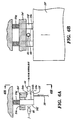
- Figure 5 depicts a first configuration of the registration pin 18 and registration bar 24 which provides information to the engine controller, and hence to the system operator, regarding the proper alignment of the loaded medium.
- the sheet of medium 10' being loaded onto the support surface 22 of the cylindrical drum 20 makes contact with the registration pin member 18a which is spring mounted on slide pins 18c.
- the springs 18b have one end abutting the pin member 18a and a second end abutting the insulating bushings 24a which are installed in an elongated aperture formed along substantially the entire length of the registration bar 24.
- the detector circuit 30 is connected to a power source 32, and by a connector 30a to one of the slide pins 18c of the registration pin 18 and by connector 30b to the registration bar 24.
- the detector circuit 30 also includes a current detector 30c which detects a current through the detection circuit 30 when the pin member 18a of the registration pin 18 contacts the registration bar 24. As indicated, this contact occurs when contact surface 18d of the pin member 18a makes contact with contact surface 24b of the registration bar 24.
- a current flows to the current detector 30c which generates a signal to the engine controller 6 indicative of the registration pin member 18a having moved to a point of contact with the registration bar 24.
- the detection of the contact between the registration pin 18 and the registration bar 24 can be used to determine if the loaded plate 10' has been properly positioned within the cylindrical drum 20. It should be noted that, using the Figure 5 configuration, detection of the contact will occur even if the medium 10' is formed of a non-metallic material. Hence, an electrical circuit can still be utilized to detect the registration alignment of media on the mounting surface 22 even if the media is not electrically conductive.
- Figure 6A depicts an alternative configuration which can be used to ensure proper alignment of the medium 10' on the cylindrical drum mounting surface 22.
- the registration pin 18' includes a registration pin member 18e and slide members 18f.
- the slide members 18f are mounted to a springs 18g which are designed to allow movement of the pin member 18e towards and away from the contact surface 24c of the registration bar 24'.
- the slide pins 18f pass through an elongated aperture formed along substantially the full length of the registration bar 24' and are supported by a bushings 24e disposed therein.
- a light emitting diode (LED) 40 is provided to emit a radiating light beam which passes between the registration pin member 18e and the register bar 24' when not in contact.
- the light is detected by the photodiode 42 which generates a signal to the engine controller 6 indicative of no contact between the registration pin 18' and registration bar 24'. This allows the engine controller 6, and accordingly the system operator, to determine if the medium 10' is properly positioned on the support surface 22 of the cylindrical drum 20 prior to imaging the medium.
- the LED 40 and photodiode 42 are disposed between the slide pins 18f.
- the leading edge of the plate 10' makes contact with pin member 18e and pushes the pin 18' such that the slide members 18f force the springs 18g to be compressed and the contact surface 18h of the registration pin 18' to move toward the contact surface 24c of the registration bar 24'.
- the contact surfaces 18h and 24c make contact, the light from the LED 40 is totally blocked such that the photodiode 42 ceases to detect the radiating light.
- the photodiode 42 therefore stops, generating a signal to the engine controller 6 thereby indicating to the engine controller 6, and hence to the system operator, that the media 10' is in proper registration at the applicable registration pin 18'.
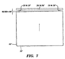
- Fgure 7 shows the movement of the sheet of medium 10' after contact between the first registration pin 18 or 18' positioned proximate to the right side of the plate 10' with the registration bar 24 or 24', while a second registration pin 18 or 18' proximate to the left side of the medium pin has yet to contact the registration bar 24 or 24', with the medium being moved in the direction indicated by the arrow.
- a skew of 0.060 inches exists at the left regisuation pin 18 or 18' when the right pin 18 or 18' contacts the registration bar 24 or 24'. Accordingly, at this point the media 10 is improperly positioned on the support surface 22 of the drum 20.
- the applicator 50 continues to move the plate 10' toward the registration bar 24 or 24'.
- the plate 10' although restricted from further movement toward the registration bar 24 or 24' on the right side of the plate, is able to slightly rotate about the right side registration pin 18 or 18'. This allows the left side of plate 10' to continue to move, pushing the left side registration pin 18 or 18' up against the registration bar 24 or 24' and thereby eliminating the skew as indicated.
- the engine controller 6 is made aware of both registration pins 18 or 18' being in register with the registration bar 24 or 24' and, accordingly, that the medium has been properly positioned for imaging on the support surface 22 of the drum 20.
- the engine controller thus processes a signal to indicate that positioning is complete and controls the scan assembly 60 to image the medium.
- the first scan line impinges upon the plate at the desired predefined position from the leading edge of the plate and parallel to the registration bar.
- the present invention provides an imaging system capable of properly positioning media of differing widths on a medium support surface prior to imaging.
- the system ensures proper alignment registration of the medium to be imaged as it is loaded onto the medium support surface, whether or not the medium is electrically conductive. If necessary, the system also squares or deskews the medium to be imaged as it is loaded onto the medium support surface.
Landscapes
- Engineering & Computer Science (AREA)
- Multimedia (AREA)
- Signal Processing (AREA)
- Registering Or Overturning Sheets (AREA)
- Studio Devices (AREA)
- Eye Examination Apparatus (AREA)
- Magnetic Resonance Imaging Apparatus (AREA)
- Facsimile Scanning Arrangements (AREA)
- Exposure And Positioning Against Photoresist Photosensitive Materials (AREA)
Claims (21)
- Belichtungssystem für Belichtungsmedien (10) unterschiedlicher Breiten bei Auflage an eine Belichtungsposition auf einer Trägeroberfläche (22), wobei das Belichtungssystem eine Ladeeinrichtung (50) enthält, die so konfiguriert ist, daß sie ein zu belichtendes Medium entlang der Trägeroberfläche zur Belichtungsposition bewegt, wobei das zu belichtende Medium so geladen wird, daß sich die Vorderkante (10a) des Mediums über eine Breite des Mediums und im wesentlichen senkrecht zu einer Bewegungsrichtung des Mediums erstreckt, umfassend:gekennzeichnet dadurch, daß sie weiterhin folgendes umfaßt:eine Paßeinrichtung, die so konfiguriert ist, daß sie während des Ladens des Mediums ausschließlich durch die Vorderkante des Mediums berührt wird, um das Medium in der Belichtungsposition auf der Trägeroberfläche zu positionieren;einen Antriebsmechanismus (26), der so konfiguriert ist, daß er die Paßeinrichtung in eine Position bewegt, die der Breite des zu belichtenden Mediums entspricht.
- Belichtungssystem nach Anspruch 1, wobei das Medium nichtmetallisch ist.
- Belichtungssystem nach Anspruch 1, wobei:die Trägeroberfläche eine Innenoberfläche einer Zylindertrommel (20) ist undder Antriebsmechanismus die Paßeinrichtung im wesentlichen parallel zur Längsachse (X-X) der Zylindertrommel bewegt.
- Belichtungssystem nach Anspruch 1, wobei die Paßeinrichtung eine von zwei Paßeinrichtungen ist und die andere Paßeinrichtung fixiert ist.
- Belichtungssystem nach Anspruch 1, das weiterhin folgendes umfaßt:eine Paßstange (24 oder 24') mit einer Referenzoberfläche (24b, 24c), die im wesentlichen parallel zu ihrer Längsachse ausgerichtet ist, um die Bewegung der Paßeinrichtung zu führen.
- Belichtungssystem nach Anspruch 5, wobei die Paßeinrichtung die Referenzoberfläche berührt, damit das Medium in der Belichtungsposition positioniert wird.
- Belichtungssystem nach Anspruch 5, wobei
die Vorderkante der Medien parallel zur Referenzoberfläche verläuft, wobei sich das Medium in der Belichtungsposition befindet. - Belichtungssystem nach Anspruch 1, das weiterhin folgendes umfaßt:einen Führungsmechanismus (18c, 24a), der mit der Paßeinrichtung verbunden ist und so konfiguriert ist, daß er eine Bewegung der Paßeinrichtung, die sich daraus ergibt, daß die Vorderkante des Mediums die Paßeinrichtung während des Ladens berührt, führt, wobei die Bewegung der Paßeinrichtung in der Bewegungsrichtung des Mediums erfolgt; undeine Paßstange (24 oder 24'), die so konfiguriert ist, daß sie die Bewegung der Paßeinrichtung an einem Punkt einschränkt, an dem die Paßeinrichtung die Paßstange berührt.
- Belichtungssystem nach Anspruch 8, wobei die Paßeinrichtung und die Paßstange elektrisch leitend sind, und weiterhin mit folgendem:wobei ein Kontakt der Paßeinrichtung mit der Paßstange den Erfassungskreis schließt.einer Stromquelle (32) undeinem Erfassungskreis (30c), der mit der Stromquelle verbunden ist, wobei der Kreis eine erste Verbindung (30a) an der Paßeinrichtung und eine zweite Verbindung (30b) an der Paßstange aufweist;
- Belichtungssystem nach Anspruch 8, das weiterhin folgendes umfaßt:wobei der strahlende Strahl vom optischen Detektor nicht erfaßt werden kann, wenn sich die Paßeinrichtung in Kontakt mit der Paßstange befindet.einen optischen Emitter (40), der so konfiguriert ist, daß er einen strahlenden Strahl zwischen die Paßeinrichtung und die Paßstange lenkt; undeinen optischen Detektor (42), der so konfiguriert ist, daß er den zwischen der Paßeinrichtung und der Paßstange durchlaufenden strahlenden Strahl erfaßt;
- Belichtungssystem nach Anspruch 1, wobei die Paßeinrichtung eine erste Paßeinrichtung ist, und weiterhin umfassend:wobei der erste Führungsmechanismus, wenn sich die Vorderkante des Mediums in Kontakt mit der ersten und zweiten Paßeinrichtung während des Ladens befindet, die Bewegung der ersten Paßeinrichtung führt, bis sich die erste Paßeinrichtung am ersten Punkt befindet, und der zweite Führungsmechanismus die Bewegung der zweiten Paßeinrichtung führt, bis sich die zweite Paßeinrichtung am zweiten Punkt befindet.eine zweite Paßeinrichtung;einen ersten Führungsmechanismus (18c, 24a), der mit der ersten Paßeinrichtung verbunden ist und so konfiguriert ist, daß er eine Bewegung der ersten Paßeinrichtung in der Bewegungsrichtung des Mediums führt;einen zweiten Führungsmechanismus (18c, 24a), der mit der zweiten Paßeinrichtung verbunden ist und so konfiguriert ist, daß er eine Bewegung der zweiten Paßeinrichtung in die Bewegungsrichtung des Mediums führt; undeine Paßstange (24 oder 24'), die so konfiguriert ist, daß sie die Bewegung der ersten Paßeinrichtung an einem ersten Punkt, an dem die erste Paßeinrichtung die Paßstange berührt, und die Bewegung der zweiten Einrichtung an einem zweiten Punkt, an dem die zweite Paßeinrichtung die Paßstange berührt, einschränkt;
- Belichtungssystem nach Anspruch 11, wobei der zweite Führungsmechanismus die Bewegung der zweiten Paßeinrichtung führt, nachdem sich die erste Paßeinrichtung am ersten Punkt befindet.
- Belichtungssystem nach Anspruch 1, das weiterhin folgendes umfaßt:wobei der Antriebsmechanismus die Kontaktoberfläche der Paßstange kontaktiert, um dadurch eine fixierte relative Positionierung der Paßeinrichtung und der Paßstange bereitzustellen.einen Führungsmechanismus (18c, 24a), der mit der Paßeinrichtung verbunden ist und so konfiguriert ist, daß er eine Bewegung der Paßeinrichtung, die sich daraus ergibt, daß die Vorderkante des Mediums die Paßeinrichtung während des Ladens berührt, führt, wobei die Bewegung der Paßeinrichtung in die Bewegungsrichtung des Mediums erfolgt; undeine Paßstange (24 oder 24') mit einer Oberfläche (24b, 24c), die konfiguriert ist, die Paßeinrichtung zu kontaktieren, um die Bewegung der Paßeinrichtung an einem Punkt einzuschränken, an dem die zugeordnete Paßeinrichtung die Paßstange berührt,
- Verfahren zum Positionieren von Belichtungsmedien (10) unterschiedlicher Breiten, die an einer Belichtungsposition auf einer Trägeroberfläche (22) aufliegen sollen, mit den folgenden Schritten:Bewegen (26) einer Paßeinrichtung derart, daß sie so positioniert ist, daß sie einer Breite eines zu belichtenden Mediums entspricht;Bewegen (50) des zu belichtenden Mediums (10') entlang der Trägeroberfläche zur Belichtungsposition, wobei sich eine Vorderkante des Mediums (10a) über die Breite des Mediums und im wesentlichen senkrecht zu einer Bewegungsrichtung des Mediums erstreckt;Kontaktieren der Paßeinrichtung ausschließlich mit der Vorderkante des zu belichtenden Mediums während der Bewegung des Mediums, um das Medium in der Belichtungsposition auf der Trägeroberfläche zu positionieren.
- Belichtungsverfahren nach Anspruch 14, wobei:die Trägeroberfläche zylindrisch ist unddie Paßeinrichtung im wesentlichen parallel zur Längsachse (X-X) der zylindrischen Trägeroberfläche bewegt wird.
- Belichtungsverfahren nach Anspruch 14, weiterhin mit den folgenden Schritten:Bewegen des Mediums, wobei die Vorderkante des Mediums die Paßeinrichtung kontaktiert, um die Paßeinrichtung in die Bewegungsrichtung des Mediums zu bewegen; undEinschränken (24b, 24c) der Bewegung der Paßeinrichtung an einem vorbestimmten Punkt.
- Belichtungsverfahren nach Anspruch 14, wobei die Bewegung der Paßeinrichtung durch eine Paßstange (24 oder 24') eingeschränkt wird und die Paßeinrichtung und die Paßstange aus einem elektrisch leitenden Material ausgebildet sind und weiterhin mit dem folgenden Schritt:Schließen eines Stromkreises (30), um dadurch einen elektrischen Strom zu leiten, indem die Paßstange mit der Paßeinrichtung kontaktiert wird.
- Belichtungsverfahren nach Anspruch 14, wobei die Bewegung der Paßeinrichtung durch eine Paßstange eingeschränkt wird, und weiterhin mit den folgenden Schritten:Lenken eines strahlenden Strahls (40) zwischen die Paßeinrichtung und die Paßstange;Erfassen (42) des zwischen der Paßeinrichtung und der Paßstange durchlaufenden strahlenden Strahls;Blockieren des Durchlaufens des strahlenden Strahls zwischen der Paßeinrichtung und der Paßstange durch Bewegen der Paßeinrichtung in Kontakt mit der Paßstange.
- Belichtungsverfahren nach Anspruch 14, weiterhin mit den folgenden Schritten:wobei die Vorderkante des Mediums in Kontakt mit der anderen Paßeinrichtung steht.Bewegen einer weiteren Paßeinrichtung an eine Position, die der Breite des zu belichtenden Mediums entspricht;Kontaktieren der anderen Paßeinrichtung mit der Vorderkante des zu belichtenden Mediums während der Bewegung des Mediums, um das Medium in der Belichtungsposition auf der Trägeroberfläche zu positionieren;Bewegen des Mediums mit der Vorderkante des Mediums bei Kontakt mit der Paßeinrichtung, um die Paßeinrichtung in der Bewegungsrichtung des Mediums zu bewegen;Bewegen der Vorderkante des Mediums bei Kontakt mit der anderen Paßeinrichtung, um die andere Paßeinrichtung in die Bewegungsrichtung des Mediums zu bewegen; undEinschränken der Bewegung der Paßeinrichtung an einem ersten vorbestimmten Punkt, wobei sich die Vorderkante des Mediums in Kontakt mit der Paßeinrichtung befindet, wobei die Bewegung der anderen Paßeinrichtung fortgesetzt wird, bis sich die andere Paßeinrichtung an einem zweiten vorbestimmten Punkt befindet,
- Belichtungssystem nach Anspruch 1, das weiterhin folgendes umfaßt:wobei der Antriebsmechanismus die Paßeinrichtung als Reaktion auf das Signal an eine Position bewegt, die der Breite des zu belichtenden Mediums entspricht.ein Signalgenerator (2) zum Erzeugen eines Signals, das die Breite des zu belichtenden Mediums darstellt;
- Belichtungssystem nach Anspruch 20, das weiterhin folgendes umfaßt:wobei der Signalgenerator das Signal als Reaktion auf die Auswahl erzeugt.eine Eingabeeinrichtung zum Auswählen eines von mehreren Medien unterschiedlicher Breiten zum Belichten;
Applications Claiming Priority (2)
| Application Number | Priority Date | Filing Date | Title |
|---|---|---|---|
| US868720 | 1997-06-04 | ||
| US08/868,720 US6002495A (en) | 1997-06-04 | 1997-06-04 | Imaging system with moveable registration pins |
Publications (3)
| Publication Number | Publication Date |
|---|---|
| EP0883280A2 EP0883280A2 (de) | 1998-12-09 |
| EP0883280A3 EP0883280A3 (de) | 2000-02-23 |
| EP0883280B1 true EP0883280B1 (de) | 2003-09-03 |
Family
ID=25352205
Family Applications (1)
| Application Number | Title | Priority Date | Filing Date |
|---|---|---|---|
| EP98110170A Expired - Lifetime EP0883280B1 (de) | 1997-06-04 | 1998-06-04 | Abbildungssystem mit beweglichem Ausrichtstift |
Country Status (5)
| Country | Link |
|---|---|
| US (1) | US6002495A (de) |
| EP (1) | EP0883280B1 (de) |
| JP (1) | JPH1117899A (de) |
| AT (1) | ATE249124T1 (de) |
| DE (1) | DE69817678T2 (de) |
Families Citing this family (6)
| Publication number | Priority date | Publication date | Assignee | Title |
|---|---|---|---|---|
| CN1043178C (zh) * | 1993-08-11 | 1999-05-05 | 北京市农林科学院作物研究所 | 花粉植物生长调节剂的生产方法 |
| US6233038B1 (en) * | 1997-06-04 | 2001-05-15 | Agfa Corporation | Imaging system with integral punch mechanism |
| US6144886A (en) * | 1997-07-02 | 2000-11-07 | Samsung Electronics Co., Ltd. | Method for detecting leading edge of print medium |
| US6661506B2 (en) * | 2000-08-24 | 2003-12-09 | Og Technologies, Inc. | Engine bearing inspection system |
| US6755132B1 (en) * | 2003-01-22 | 2004-06-29 | Creo Inc. | Registration pin system |
| US20080084591A1 (en) * | 2006-10-05 | 2008-04-10 | Rassatt Bradley B | Imaging apparatus with moveable entrance guide |
Family Cites Families (5)
| Publication number | Priority date | Publication date | Assignee | Title |
|---|---|---|---|---|
| US4750045A (en) * | 1985-08-15 | 1988-06-07 | Fuji Photo Film Co., Ltd. | Light beam scanning system |
| US4945238A (en) * | 1987-07-20 | 1990-07-31 | Fuji Photo Film Co., Ltd. | Apparatus for loading sheet-shaped material |
| US5301938A (en) * | 1992-12-17 | 1994-04-12 | Xerox Corporation | Apparatus for gripping and registering sheets |
| US5335046A (en) * | 1993-02-22 | 1994-08-02 | Intergraph Corporation | Clamping mechanism for use on a rotatable plotter drum |
| GB9509065D0 (en) * | 1995-05-04 | 1995-06-28 | Crosfield Electronics Ltd | Improvements relating to sheet handling |
-
1997
- 1997-06-04 US US08/868,720 patent/US6002495A/en not_active Expired - Lifetime
-
1998
- 1998-05-29 JP JP10164446A patent/JPH1117899A/ja active Pending
- 1998-06-04 EP EP98110170A patent/EP0883280B1/de not_active Expired - Lifetime
- 1998-06-04 AT AT98110170T patent/ATE249124T1/de not_active IP Right Cessation
- 1998-06-04 DE DE69817678T patent/DE69817678T2/de not_active Expired - Lifetime
Also Published As
| Publication number | Publication date |
|---|---|
| DE69817678D1 (de) | 2003-10-09 |
| US6002495A (en) | 1999-12-14 |
| DE69817678T2 (de) | 2004-07-15 |
| JPH1117899A (ja) | 1999-01-22 |
| ATE249124T1 (de) | 2003-09-15 |
| EP0883280A2 (de) | 1998-12-09 |
| EP0883280A3 (de) | 2000-02-23 |
Similar Documents
| Publication | Publication Date | Title |
|---|---|---|
| EP0882581B1 (de) | Ausrichtungerfassungsgerät für Bilderzeugungssystemen | |
| EP2129524B1 (de) | Druckplattenregistrierung mit einer kamera | |
| US6097475A (en) | Method and apparatus for orienting a recording media sheet on a support surface | |
| US20020011164A1 (en) | Pin registration system for mounting different width printing plates | |
| EP0944235A2 (de) | Bilderzeugungssystem mit integrierter Stanzvorrichtung | |
| EP0883280B1 (de) | Abbildungssystem mit beweglichem Ausrichtstift | |
| US6085657A (en) | Redirecting printing media in a prepress printing environment | |
| EP1081458A2 (de) | Verfahren und Apparat zur Detektion von Kanten | |
| US6772688B2 (en) | Imaging system with automated plate locating mechanism and method for loading printing plate | |
| JPS6255320B2 (de) | ||
| US6084602A (en) | Imaging system with high efficiency media loading | |
| US6772691B2 (en) | System and method for registering media in an imaging system | |
| US5938187A (en) | Media feed apparatus for an imaging device | |
| US20040041078A1 (en) | System and method for calibrating an imaging system during imaging | |
| US8240844B2 (en) | Post-imaging punching apparatus and method | |
| US20030121438A1 (en) | Apparatus and method for supporting and feeding printing plates in an imaging system | |
| EP1187449A2 (de) | Passgenaue Filmstreifen | |
| US20040051915A1 (en) | Method and apparatus for incrementally displacing recording media in an imaging system | |
| JPS62176364A (ja) | 光ビ−ム走査装置 | |
| JPH03129967A (ja) | 原稿読取り基準位置設定方法 | |
| JPS61186065A (ja) | 情報入出力装置 | |
| JPS6278966A (ja) | 光ビ−ム走査装置 | |
| JPS6278957A (ja) | 光ビ−ム記録装置 |
Legal Events
| Date | Code | Title | Description |
|---|---|---|---|
| PUAI | Public reference made under article 153(3) epc to a published international application that has entered the european phase |
Free format text: ORIGINAL CODE: 0009012 |
|
| AK | Designated contracting states |
Kind code of ref document: A2 Designated state(s): BE DE FR GB |
|
| AX | Request for extension of the european patent |
Free format text: AL;LT;LV;MK;RO;SI |
|
| RAP1 | Party data changed (applicant data changed or rights of an application transferred) |
Owner name: AGFA CORPORATION |
|
| PUAL | Search report despatched |
Free format text: ORIGINAL CODE: 0009013 |
|
| AK | Designated contracting states |
Kind code of ref document: A3 Designated state(s): AT BE CH CY DE DK ES FI FR GB GR IE IT LI LU MC NL PT SE |
|
| AX | Request for extension of the european patent |
Free format text: AL;LT;LV;MK;RO;SI |
|
| 17P | Request for examination filed |
Effective date: 20000822 |
|
| AKX | Designation fees paid |
Free format text: BE DE FR GB |
|
| 17Q | First examination report despatched |
Effective date: 20020122 |
|
| GRAH | Despatch of communication of intention to grant a patent |
Free format text: ORIGINAL CODE: EPIDOS IGRA |
|
| GRAH | Despatch of communication of intention to grant a patent |
Free format text: ORIGINAL CODE: EPIDOS IGRA |
|
| GRAA | (expected) grant |
Free format text: ORIGINAL CODE: 0009210 |
|
| RBV | Designated contracting states (corrected) |
Designated state(s): AT BE CH CY DE DK ES FI FR GB GR IE IT LI LU MC NL PT SE |
|
| AK | Designated contracting states |
Kind code of ref document: B1 Designated state(s): AT BE CH CY DE DK ES FI FR GB GR IE IT LI LU MC NL PT SE |
|
| PG25 | Lapsed in a contracting state [announced via postgrant information from national office to epo] |
Ref country code: NL Free format text: LAPSE BECAUSE OF FAILURE TO SUBMIT A TRANSLATION OF THE DESCRIPTION OR TO PAY THE FEE WITHIN THE PRESCRIBED TIME-LIMIT Effective date: 20030903 Ref country code: LI Free format text: LAPSE BECAUSE OF FAILURE TO SUBMIT A TRANSLATION OF THE DESCRIPTION OR TO PAY THE FEE WITHIN THE PRESCRIBED TIME-LIMIT Effective date: 20030903 Ref country code: IT Free format text: LAPSE BECAUSE OF FAILURE TO SUBMIT A TRANSLATION OF THE DESCRIPTION OR TO PAY THE FEE WITHIN THE PRESCRIBED TIME-LIMIT;WARNING: LAPSES OF ITALIAN PATENTS WITH EFFECTIVE DATE BEFORE 2007 MAY HAVE OCCURRED AT ANY TIME BEFORE 2007. THE CORRECT EFFECTIVE DATE MAY BE DIFFERENT FROM THE ONE RECORDED. Effective date: 20030903 Ref country code: FI Free format text: LAPSE BECAUSE OF FAILURE TO SUBMIT A TRANSLATION OF THE DESCRIPTION OR TO PAY THE FEE WITHIN THE PRESCRIBED TIME-LIMIT Effective date: 20030903 Ref country code: CY Free format text: LAPSE BECAUSE OF FAILURE TO SUBMIT A TRANSLATION OF THE DESCRIPTION OR TO PAY THE FEE WITHIN THE PRESCRIBED TIME-LIMIT Effective date: 20030903 Ref country code: CH Free format text: LAPSE BECAUSE OF FAILURE TO SUBMIT A TRANSLATION OF THE DESCRIPTION OR TO PAY THE FEE WITHIN THE PRESCRIBED TIME-LIMIT Effective date: 20030903 Ref country code: AT Free format text: LAPSE BECAUSE OF FAILURE TO SUBMIT A TRANSLATION OF THE DESCRIPTION OR TO PAY THE FEE WITHIN THE PRESCRIBED TIME-LIMIT Effective date: 20030903 |
|
| REG | Reference to a national code |
Ref country code: GB Ref legal event code: FG4D |
|
| REG | Reference to a national code |
Ref country code: CH Ref legal event code: EP |
|
| REF | Corresponds to: |
Ref document number: 69817678 Country of ref document: DE Date of ref document: 20031009 Kind code of ref document: P |
|
| REG | Reference to a national code |
Ref country code: IE Ref legal event code: FG4D |
|
| PG25 | Lapsed in a contracting state [announced via postgrant information from national office to epo] |
Ref country code: SE Free format text: LAPSE BECAUSE OF FAILURE TO SUBMIT A TRANSLATION OF THE DESCRIPTION OR TO PAY THE FEE WITHIN THE PRESCRIBED TIME-LIMIT Effective date: 20031203 Ref country code: GR Free format text: LAPSE BECAUSE OF FAILURE TO SUBMIT A TRANSLATION OF THE DESCRIPTION OR TO PAY THE FEE WITHIN THE PRESCRIBED TIME-LIMIT Effective date: 20031203 Ref country code: DK Free format text: LAPSE BECAUSE OF FAILURE TO SUBMIT A TRANSLATION OF THE DESCRIPTION OR TO PAY THE FEE WITHIN THE PRESCRIBED TIME-LIMIT Effective date: 20031203 |
|
| PG25 | Lapsed in a contracting state [announced via postgrant information from national office to epo] |
Ref country code: ES Free format text: LAPSE BECAUSE OF FAILURE TO SUBMIT A TRANSLATION OF THE DESCRIPTION OR TO PAY THE FEE WITHIN THE PRESCRIBED TIME-LIMIT Effective date: 20031214 |
|
| NLV1 | Nl: lapsed or annulled due to failure to fulfill the requirements of art. 29p and 29m of the patents act | ||
| PG25 | Lapsed in a contracting state [announced via postgrant information from national office to epo] |
Ref country code: PT Free format text: LAPSE BECAUSE OF FAILURE TO SUBMIT A TRANSLATION OF THE DESCRIPTION OR TO PAY THE FEE WITHIN THE PRESCRIBED TIME-LIMIT Effective date: 20040203 |
|
| REG | Reference to a national code |
Ref country code: CH Ref legal event code: PL |
|
| ET | Fr: translation filed | ||
| PG25 | Lapsed in a contracting state [announced via postgrant information from national office to epo] |
Ref country code: LU Free format text: LAPSE BECAUSE OF NON-PAYMENT OF DUE FEES Effective date: 20040604 Ref country code: IE Free format text: LAPSE BECAUSE OF NON-PAYMENT OF DUE FEES Effective date: 20040604 |
|
| PG25 | Lapsed in a contracting state [announced via postgrant information from national office to epo] |
Ref country code: MC Free format text: LAPSE BECAUSE OF NON-PAYMENT OF DUE FEES Effective date: 20040630 Ref country code: BE Free format text: LAPSE BECAUSE OF NON-PAYMENT OF DUE FEES Effective date: 20040630 |
|
| PLBE | No opposition filed within time limit |
Free format text: ORIGINAL CODE: 0009261 |
|
| STAA | Information on the status of an ep patent application or granted ep patent |
Free format text: STATUS: NO OPPOSITION FILED WITHIN TIME LIMIT |
|
| 26N | No opposition filed |
Effective date: 20040604 |
|
| REG | Reference to a national code |
Ref country code: FR Ref legal event code: D6 |
|
| REG | Reference to a national code |
Ref country code: GB Ref legal event code: 746 Effective date: 20041110 |
|
| BERE | Be: lapsed |
Owner name: *AGFA CORP. Effective date: 20040630 |
|
| REG | Reference to a national code |
Ref country code: IE Ref legal event code: MM4A |
|
| PGFP | Annual fee paid to national office [announced via postgrant information from national office to epo] |
Ref country code: GB Payment date: 20140425 Year of fee payment: 17 |
|
| PGFP | Annual fee paid to national office [announced via postgrant information from national office to epo] |
Ref country code: FR Payment date: 20140425 Year of fee payment: 17 Ref country code: DE Payment date: 20140425 Year of fee payment: 17 |
|
| REG | Reference to a national code |
Ref country code: DE Ref legal event code: R119 Ref document number: 69817678 Country of ref document: DE |
|
| GBPC | Gb: european patent ceased through non-payment of renewal fee |
Effective date: 20150604 |
|
| REG | Reference to a national code |
Ref country code: FR Ref legal event code: ST Effective date: 20160229 |
|
| PG25 | Lapsed in a contracting state [announced via postgrant information from national office to epo] |
Ref country code: GB Free format text: LAPSE BECAUSE OF NON-PAYMENT OF DUE FEES Effective date: 20150604 Ref country code: DE Free format text: LAPSE BECAUSE OF NON-PAYMENT OF DUE FEES Effective date: 20160101 |
|
| PG25 | Lapsed in a contracting state [announced via postgrant information from national office to epo] |
Ref country code: FR Free format text: LAPSE BECAUSE OF NON-PAYMENT OF DUE FEES Effective date: 20150630 |