EP0883324A2 - Méthode et interface pour rélier le traffic de communication entre les réseaux à large bande et à bande étroite - Google Patents
Méthode et interface pour rélier le traffic de communication entre les réseaux à large bande et à bande étroite Download PDFInfo
- Publication number
- EP0883324A2 EP0883324A2 EP98304419A EP98304419A EP0883324A2 EP 0883324 A2 EP0883324 A2 EP 0883324A2 EP 98304419 A EP98304419 A EP 98304419A EP 98304419 A EP98304419 A EP 98304419A EP 0883324 A2 EP0883324 A2 EP 0883324A2
- Authority
- EP
- European Patent Office
- Prior art keywords
- network
- channel
- control
- call
- traffic
- Prior art date
- Legal status (The legal status is an assumption and is not a legal conclusion. Google has not performed a legal analysis and makes no representation as to the accuracy of the status listed.)
- Granted
Links
Images


Classifications
-
- H—ELECTRICITY
- H04—ELECTRIC COMMUNICATION TECHNIQUE
- H04Q—SELECTING
- H04Q11/00—Selecting arrangements for multiplex systems
- H04Q11/04—Selecting arrangements for multiplex systems for time-division multiplexing
- H04Q11/0428—Integrated services digital network, i.e. systems for transmission of different types of digitised signals, e.g. speech, data, telecentral, television signals
- H04Q11/0478—Provisions for broadband connections
-
- H—ELECTRICITY
- H04—ELECTRIC COMMUNICATION TECHNIQUE
- H04L—TRANSMISSION OF DIGITAL INFORMATION, e.g. TELEGRAPHIC COMMUNICATION
- H04L12/00—Data switching networks
- H04L12/28—Data switching networks characterised by path configuration, e.g. LAN [Local Area Networks] or WAN [Wide Area Networks]
- H04L12/46—Interconnection of networks
- H04L12/4604—LAN interconnection over a backbone network, e.g. Internet, Frame Relay
- H04L12/4608—LAN interconnection over ATM networks
-
- H—ELECTRICITY
- H04—ELECTRIC COMMUNICATION TECHNIQUE
- H04L—TRANSMISSION OF DIGITAL INFORMATION, e.g. TELEGRAPHIC COMMUNICATION
- H04L12/00—Data switching networks
- H04L12/54—Store-and-forward switching systems
- H04L12/56—Packet switching systems
- H04L12/5601—Transfer mode dependent, e.g. ATM
- H04L2012/5614—User Network Interface
- H04L2012/5618—Bridges, gateways [GW] or interworking units [IWU]
-
- H—ELECTRICITY
- H04—ELECTRIC COMMUNICATION TECHNIQUE
- H04L—TRANSMISSION OF DIGITAL INFORMATION, e.g. TELEGRAPHIC COMMUNICATION
- H04L12/00—Data switching networks
- H04L12/54—Store-and-forward switching systems
- H04L12/56—Packet switching systems
- H04L12/5601—Transfer mode dependent, e.g. ATM
- H04L2012/5629—Admission control
- H04L2012/563—Signalling, e.g. protocols, reference model
-
- H—ELECTRICITY
- H04—ELECTRIC COMMUNICATION TECHNIQUE
- H04L—TRANSMISSION OF DIGITAL INFORMATION, e.g. TELEGRAPHIC COMMUNICATION
- H04L12/00—Data switching networks
- H04L12/54—Store-and-forward switching systems
- H04L12/56—Packet switching systems
- H04L12/5601—Transfer mode dependent, e.g. ATM
- H04L2012/5638—Services, e.g. multimedia, GOS, QOS
- H04L2012/5646—Cell characteristics, e.g. loss, delay, jitter, sequence integrity
- H04L2012/5652—Cell construction, e.g. including header, packetisation, depacketisation, assembly, reassembly
- H04L2012/5653—Cell construction, e.g. including header, packetisation, depacketisation, assembly, reassembly using the ATM adaptation layer [AAL]
Definitions
- This invention relates, generally, to a communication system architecture and operating protocol therefor, and is particularly, but not exclusively, applicable to an interface arrangement that integrates a local area network (LAN), typically operating in a wide-band context, with a broadband virtual circuit-switched system, such as envisaged and implemented in Asynchronous Transmission Mode (ATM) networks.
- LAN local area network
- ATM Asynchronous Transmission Mode
- Telephony systems have evolved from simplistic hard-wired interconnected networks to broadband, high capacity systems that support multimedia, multi-mode communication devices on local area networks (LANs) and packet-switched communication systems. Indeed, instead of having to rely entirely on dedicated land-line infrastructure, present day technologies now occupy virtual channel environments in both the radio frequency and land-line domains.
- LANs local area networks
- packet-switched communication systems instead of having to rely entirely on dedicated land-line infrastructure, present day technologies now occupy virtual channel environments in both the radio frequency and land-line domains.
- GB-A-2311690 describes the merging of two networks in which a telephone subsystem is connected to a packet-switched broadband backbone and in which telephony is added to the backbone without interfering with packetised data.
- GB-A-2309362 is a mechanism for interconnecting broadband and narrowband networks and is generally related to the present field of the present invention.
- WO 96/06492 is an arrangement for supplying local network emulation service over a public connectionless ATM network. More specifically, a server acts as an address resolver and as a relay for routing traffic. SynOptics US patent 5420858 describes the segmentation and re-assembly of information between non-ATM messages and ATM cells.
- US-A-5528590 describes the transfer of data between an ATM-UNI interface and an ATM-LAN interface in a manner such that the ATM-UNI interface recognises frames and assembles and ATM cells into these frames. More particularly, the system can determine whether or not there is enough capacity on the LAN interface for the frame, and only if there is enough capacity is the frame transferred via a ATM switch to the ATM-LAN interface and then onwards to the LAN.
- a method of connecting a first network to a second network via an intermediate network the first network and second network using a set of control messages to control media paths between the first network and the second network
- the method characterised by the steps of: establishing a control channel across the intermediate network to carry the set of control messages; intercepting the set of control messages in the intermediate network and determining a requirement for media paths in response thereto; in response to the determination, setting up media paths in the intermediate network to connect paths to carry media traffic between the first network and the second network.
- a method of connecting communication traffic comprised of a plurality traffic components across a broadband network from a local area network characterised by the steps of: in the local area network, generating control messages for controlling the traffic components and applying these control messages to an interface of the broadband network; establishing a communication path within the broadband network to carry at least one of the plurality of traffic components; and in the broadband network, using the control messages to control transfer of the plurality of traffic components over the communication path.
- LAN local area network
- the LAN streams include audio, video, data and control streams
- the method further comprising the step of interpreting the control streams to set-up mini-channels used to carry at least one of an audio, video and a data communication.
- connection supervisor for orchestrating the communication of traffic components between first and second networks via an intermediate network, the connection supervisor responsive to control messages communicated between the first and second networks, the connection supervisor including: means for setting-up a communication path for carrying the control messages across the intermediate network; means for determining types of control message sent across the communication path; and means for establishing media paths dependent upon types of control message sent across the communication path, the media paths arranged to transfer the traffic components across the intermediate network.
- a communication node having a gateway that provides an interfaces to a first end-point in a network, the first end-point arranged to initiate a call through the communication node by sending to the gateway a called party number of a second end-point coupled to an exchange and wherein control messages are communicated between the first end-point and the second end-point
- the communication node characterised by: a call handler coupled to the gateway and responsive to the called party number, the call handler arranged to select a route to the exchange; and a connection supervisor, coupled to the call handler and operationally responsive thereto, the connection supervisor having: i) means to set-up a control channel that supports transfer of the control messages between the gateway and the exchange in response to the call handler receiving the called party number; ii) means for determining types of control message sent across the control channel; and iii) means for establishing media paths between the gateway and the exchange (118) dependent upon types of control message sent across the control channel, the media paths arranged
- the communication node is a broadband network and the control channel and the media paths are virtual channels.
- the preferred embodiments of the present invention generally provide an ability of interconnecting a first LAN-compatible system (such as a WAN) through a seamless public or private broadband network (supporting narrowband or broadband telephony) to another LAN-compatible system.
- a first LAN-compatible system such as a WAN
- seamless public or private broadband network supporting narrowband or broadband telephony
- FIG. 1 there is shown a block diagram of a prior art local area network (LAN) 10 suitable for supporting an Ethernet connection regime, or the like.
- the LAN 10 operates in a bursty fashion and provides packets of data over an H.323 signalling scheme, or similar messaging protocol.
- the H.323 signalling scheme defines the functionality of the multimedia terminal 12, the signalling protocols utilised within the LAN 10, the types of terminals suitable for use with the LAN 10 and the transmission protocols adopted for use by the multimedia terminal 12.
- the LAN 10 can support a multitude of multimedia terminals offering differing levels of functionality to each user thereof.
- H.323 In a LAN environment a limited bandwidth supports numerous packet-based communications that vie for the available bandwidth.
- port addresses of a first end point are associated with port addresses of a second end point, with the resultant interconnection between pairs of port addresses referred to (generally) as an H.323 channel.
- end point relates to a terminal, a gatekeeper or a gateway (the functions of which will be described later).
- Each H.323 video or audio channel can be a wideband channel presently supporting data up to a rate of 2Mbps.
- the multimedia terminal 12 and the multimedia gateway 20 each have unique port addresses through which communication (interconnection) is established.
- Each port address is typically comprised of the LAN address and a port number, with the LAN address usually common to a specific piece of equipment (i.e. the gateway 20 or a multimedia terminal).
- a dedicated call signalling channel 14 couples the multimedia terminal 12 to a first multimedia gatekeeper 16, which first multimedia gatekeeper 16 is, in turn, coupled to a second multimedia gatekeeper 18 through the call signalling channel 14.
- the second multimedia gatekeeper 18 is further coupled to a multimedia gateway 20 (or "multimedia termination point", such as a printer) through the call signalling channel 14.
- Both the first multimedia gatekeeper 16 and the second multimedia gatekeeper 18 are, respectively, coupled to the multimedia terminal 12 and the multimedia gateway 20 via a registration, admission and status (RAS) channel 22-24
- the call signalling channel uses the H.323 signalling protocol.
- the use of either or both gatekeepers is optional and is included for a more complete understanding of a set-up of a H.323 call.
- the function of the multimedia gatekeeper is principally to translate LAN addresses into appropriate network addresses, and to negotiate and control bandwidth requirements for a proposed H.323 communication.
- the gatekeeper operates to translate the alias address into a usable network or LAN address.
- a processor in the gatekeeper will typically access a look-up table (shown only in relation to the second gatekeeper 18 for clarity) to ascertain the usable network or LAN address, whereafter the gatekeeper updates the multimedia terminal 12 with the usable network or LAN address via the RAS 22.
- the network address is analogous to a telephone number in a conventional telephone system, although the network address may be formulated in such a way that it can address multiple terminals simultaneously.
- multimedia gatekeepers 16-18 may be co-located with the multimedia terminal 12 and the multimedia gateway 20, and are illustrated as distinct blocks for the sake of explanation. While the LAN is described as having a multimedia gateway 20 (that provides access to different networks having different signalling protocols via a signalling channel resource 34, a control channel resource 36 and channels 38 that support audio, video and/or data), the gateway 20 could be substituted for a second multimedia terminal or a multi-point control unit (namely a conference bridge).
- the LAN 10 operates with three principal signalling schemes for each multimedia call. The purpose and function of these schemes will now be described.
- Call signalling information is communicated along the call signalling channel 14 and is arranged, principally, to set-up and clear-down calls.
- Call signalling information generally includes routing information (e.g. the network or LAN address), acknowledge back signalling, connection request/release instructions and input/output port addresses. Assuming that a suitable network address is eventually output from an end point, e.g. multimedia terminal 12, the network address is passed along the call signalling channel 14 and routed via at least the first multimedia gatekeeper 16 (and probably the second multimedia gatekeeper 18) to a receiving end point, e.g. the multimedia gateway 20.
- the network address is typically encoded in a set-up message, as will readily be appreciated, and also identifies the port for the negotiation control channel 26 that the multimedia terminal 12 intends to use.
- the set-up message sent from the multimedia terminal 12, causes the receiving unit (in this example, the gateway 20) to respond by sending a port identification and LAN terminal address over the call signalling channel 14.
- the receiving unit in this case the multimedia gateway 20
- the receiving unit identifies to the multimedia terminal 12 which port the receiving unit intends to use for the negotiation control channel 26.
- both the requesting multimedia terminal 12 and the called party each possess an address of a port to which communications on the LAN 10 are to be directed.
- the call signalling channel 14 is used to administer overall system control, while the negotiation control channel 26 (established between the identified port addresses) is used for two principal purposes.
- the negotiation control channel 26 is used to communicate in-call channel information, such as timing information, channel frequency information, data rates and bandwidth allocations.
- the negotiation control channel 26 is used to identify the port addresses (at all terminals) and to control transmissions on the audio stream 28, video stream 30 and data stream 32.
- the negotiation control channel 26 may utilise H 245 signalling or the like.
- broadband networks such as those which utilise ATM, are derived from circuit switched telephony and so typically exhibit several intermediate signalling layers between a broadband user 50 and a physical infrastructure layer 52. More particularly, there is usually at least one intermediate enveloping protocol layer 54 juxtaposed to the broadband user 50, while an ATM (packet-switched) signalling protocol layer 56 is sandwiched between the physical infrastructure layer 52 and the enveloping protocol layer 54.
- ATM packet-switched
- user information provided by the broadband user 50 is first packaged into defined protocol envelopes (by the enveloping protocol layer 54), which envelopes are then compressed into a packet-switched format by the ATM signalling protocol layer 56. Once fully packaged, information can be transmitted across the broadband network through the physical layer 52.
- a broadband network utilises a transfer protocol in which virtual channels are circuit-switched and which provides a provisioned (but varying) bandwidth.
- Broadband networks can utilise ATM and AAL-2 (ATM Adaptation Layer 2); the latter is a subset of ATM that provides switching at a virtual sub-channel level in an ATM environment
- ATM AAL-2
- AAL-5 AAL-1 is an ATM adaptation protocol originally targeted at constant bit rate (CBR) traffic, e.g. voice or video, and is applicable to data rates equal to or exceeding sixty-four kbps.
- AAL-5 provides a capability of data, voice and video transmissions to work stations, and is therefore particularly applicable to multimedia communication systems.
- AAL-5 segments long data structures into many cells, with a data structure conceivably exceeding fifteen hundred octets in length.
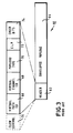
- the data frame structure 60 comprises a header 62 of control information and an enveloped payload 64.
- the header 62 comprises a virtual path identifier 66 and a virtual channel identifier 68 that together co-operate to identify a circuit-switched path (i.e. a virtual channel) through the broadband network.
- the circuit-switched path is therefore set at the beginning of a call and only released at the end of the call.
- the header 62 further includes an indication of payload type 70, and an indication termed cell loss priority 72 that stipulates whether the communication on the virtual channel can be dropped to support higher priority communications.
- cell loss priority 72 stipulates whether the communication on the virtual channel can be dropped to support higher priority communications.
- the header 62 includes check-bits for error detection and correction, although the header 62 may optionally include dedicated flow control bits 76 used in quasi-broadband systems to enhance data rate capacity over existing communication resources, e.g. by superimposing high frequency channels over an existing two-wire scheme. More particularly, the generic flow control bits act as negotiation bits and request the assignment of bandwidth, for example, from a system controller (not shown).
- the enveloped payload 64 which is of fixed length, will now be described in more detail in relation to FIG. 4 in which there is shown a typical mechanism by which data is "nested" within the payload envelope 64 of FIG 3.
- data that is ultimately to be nested within the payload envelope 64 can vary in length, and can be comprised from distinct data portions. Indeed, a combination of the individual data portions can produce a data string having an overall length that exceeds the length of the payload envelope 64. Consequently, the data may be encoded using known techniques so as to optimise nesting of the data into the payload envelope 64.
- data 82 is preceded by a start-field octet 84 comprising an offset field 86, a sequence number 88 and parity bit 90.
- start-field octet 84 comprising an offset field 86, a sequence number 88 and parity bit 90.
- SDU service data unit
- the data 82 (which, in this instance, usually varies in length) is preceded by a packet header 94 comprising a channel identifier 96, a length indicator 98, a user-to-user indication 100 and check bits 102.
- the channel identifier 96 identifies a "mini-channel" that uniquely supports a solitary communication.
- the length indicator 98 identifies the length of the data portion.
- the functions of the constituent parts of the packet header 94 are detailed in ITU standards document 1.363.2
- FIG. 3 and FIG. 4 demonstrate the stack concept illustrated in FIG. 2.
- the PDU and SDU layers for AAL-1 and AAL-5 vary from the structure of AAL-2, but both form stacks within ATM in a similar fashion to that described above, as will be readily appreciated.
- the present invention provides a mechanism for the interconnection of a LAN to a broadband network, perhaps implemented using ATM.
- a broadband network perhaps implemented using ATM.
- elements common with the prior art contain identical reference numerals to those of the earlier drawing figures.
- the LAN 10 provides a capability of interconnecting communication devices (i.e. multimedia endpoints 110), such as computers (having Internet capabilities) and multimedia terminals 12 and other multimedia devices.
- multimedia endpoints 110 such as computers (having Internet capabilities)
- multimedia terminals 12 and other multimedia devices.
- the LAN 10 may also support a gatekeeper 16.
- a communication resource 111 coupled to a gateway interface circuit 112, supports the transmission of RAS bits and provides a dedicated call signalling channel, a dedicated negotiation control channel and audio, video and data streams (as previously described and shown in relation to FIG. 2, albeit not specifically shown in this drawing figure).
- the gateway interface circuit 112 couples call signalling messages 114 to a call handler 116, typically arranged to support an integrated service digital network (ISDN) methodology (either narrowband, broadband or a hybrid).
- ISDN integrated service digital network
- the call signalling messages 114 are used to set-up and clear-down calls, and are also used to identify multimedia terminal addresses and the like.
- the call handler 116 is, in turn, coupled to a succession of other exchanges 118 through a semi-permanent call signalling channel 115. At least one subscriber terminal 119 is coupled to each other exchange, with the subscriber terminal 119 having a unique address.
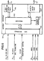
- the connection supervisor 120 is connected through a control line 124 to the call handler 116.
- the connection supervisor 120 is arranged to supervise the control of both a mini-channel switch 126 and a virtual channel switch 128 via control lines 130 and 132, respectively.
- the virtual channel switch 128 is coupled to the gateway interface 112 via a first virtual channel resource 134 supporting (in the exemplary context of AAL-2) enveloped mini-channel payloads, e.g. H.245 negotiation control messages, and audio, video or data packets.
- the virtual channel switch 128 routes the payloads received on the first virtual channel resource 134 through the mini-channel switch 126, which mini-channel switch 126 is arranged to optimise call transmissions ultimately output by the virtual channel switch 128 on the second virtual channel resource 140.
- the second virtual channel resource 140 leads to the other exchange 11 8.
- connection supervisor 120 provides a dual function. First, it acts to control the virtual channel switch 128 (via control line 132), and the mini-channel switch 126 (via control line 130). Second, the connection supervisor 120 also functions to receive, process and generate H.245 messages for H.323 calls. In this latter respect, H.245 messages are routed between the first virtual channel resource 134 and the connection supervisor 120 and also between the connection supervisor 120 and the second virtual channel resource 140, with both routings being via the virtual channel switch 128 and the mini-channel switch 126.
- the gateway interface 112, the call handler 116, the connection supervisor 120, the virtual channel switch 128 and the mini-channel switch 126 constitute parts of an exchange (or node) 142.
- the exchange 142 further includes a protocol interworking processor 144 that translates between AAL-1, AAL-2 and AAL-5.
- This protocol interworking processor 144 is coupled to the virtual channel switch 128.
- the protocol interworking processor 144 is operationally responsive to the connection supervisor 120 (via control line 145).
- the mini-channel switch 126 is not required in relation to AAL-1 and AAL-5 specific calls.
- H.245 messages carried on AAL-5 instead of AAL-2 are routed solely through the virtual channel switch and through the connection supervisor; this connection is not shown for the sake of clarity of FIG. 5
- FIG. 6 illustrates the structure of the gateway interface 112 in greater detail and also according to a preferred embodiment of the present invention.
- the gateway interface 112 is responsive to a LAN 10 and receives, at LAN interface 150, an H.225.0 RAS control channel 22, an H.225.0 call signalling channel 14, an H.245 negotiation control channel 26 and audio streams 28, video streams 30 and data streams 32.
- a processor 152 coupled to a memory device 154, controls the routing of the various input channels and streams (applied to the LAN interface 150) to appropriate output interfaces.
- a call signalling interface 156 receives a translated version of signalling messages received on the H.225 call signalling channel 14, i.e. the processor 152 and memory device 154 co-operate to translate incoming call signalling messages into an acceptable broadband format, such as DSS1/DSS2, for onward routing (via the control signalling channel 114) to the call handler 116.
- the processor 152 also packages control messages (received on the negotiation control channel 26) and information (received on the audio, video and data streams 28-32) into a mini-channel format suitable for use in the broadband network. This mini-channel format is output through a broadband ATM/virtual channel interface 158 to the first virtual channel resource 134.
- the memory device 154 acts as a storage medium for temporarily storing information passing between the LAN and a broadband network, and also contains look-up tables associated with address and routing information, active call and connection information, and signalling protocol translation schemes used to translate LAN signalling to narrowband/broadband signalling.
- the gateway interface 112 In response to receiving conventional LAN streams from the call signalling channel 14 (step 200 of FIG. 7), the gateway interface 112 first converts call signalling information (received on the call signalling channel 14) into an appropriate format, such as DSS1, and forwards this onward to the call handler 116. More particularly, as will now be understood, the call signalling information contains an address of a called party (normally as a telephone number, although an E-mail address can also be used) and an identity (e.g. a telephone number and/or E-mail address) of a requesting multimedia terminal. As such, it might be necessary to translate (at least) the address of the called party into a format acceptable to the broadband network (step 202). In other words, the gateway interface may need to generate a telephone number for use in the broadband network.
- This address mapping process can be executed within the call hander 116 or within the gateway interface 112, after which the communication system begins to establish a connection.
- data received by the gateway interface 112 (by way of the audio, video and data streams 28-32 and the negotiation control channel 26) will typically need to be stored, temporarily, in memory 154.
- the LAN streams can be considered as forming distinct traffic components in the call.
- the call handler selects an outgoing route, i.e. the next exchange 118, and a trunk circuit leading to that next exchange (step 204).
- the connection supervisor 120 is then notified of the selected trunk circuit.
- the call handler can send an SS7 IAM to the next exchange 118 (via the call signalling channel 115), but there is an associated risk because, at this time, there is no guarantee that a successful path can be set up across exchange 142.
- the relevant next exchange 118 responds to the call handler 116 and identifies/confirms the address identity or identities that, respectively, has or have been ear-marked for the call; this mechanism is therefore analogous to the prior art procedure described in relation to FIG. 1.
- the call handler 116 sends the identity of a selected trunk circuit to the connection supervisor 120 which in turn makes the connections across the virtual channel switch 128 and mini-channel switch 126 (as appropriate) to connect the H.245 control channel on the first virtual channel resource 134 to the connection supervisor 120 and then onto the second virtual channel resource 140 (step 206).
- the call handler is under the impression that it is setting up a whole trunk call whereas, in fact, the call handler 116 is only setting up the H.245 negotiation control channel.
- the calling party dials the number of the called party and, in response thereto, the call handler 116 analyses the called number and selects out-going route (based on the called number) to next exchange 118.
- the call handler 116 selects a trunk circuit belonging to the out-going route, although this function may be performed by the connection supervisor 120.
- the call handler 116 Rather than asking the virtual channel switch 128 to set-up media paths for the call, the call handler 116 then asks connection supervisor 120 to set-up the call.
- Step 206 is now described in more detail.
- the connection supervisor 120 interacts with the gateway interface 112, the virtual channel switch 128 and the mini-channel switch 126 to orchestrate a broadband connection.
- a first step requires the selection of a first mini-channel of the first virtual channel resource 134, which mini-channel is incident to the gateway interface 112.
- the connection supervisor 120 makes the selection of the first mini-channel.
- a first connection is made (through use of control channels 130-132) between the gateway interface 112 and the connection supervisor 120, which connection uses the first mini-channel and is made via the virtual channel switch 128 and the mini-channel switch 126
- the connection supervisor uses the trunk circuit identity (received from the call handler 116) to select a virtual channel and a second mini-channel from the available virtual channels of the second virtual channel resource 140.
- a second connection is then made between the connection supervisor 120 and the other exchange 118 using the selected virtual channel and the second mini-channel via the virtual channel switch 128 and the mini-channel switch 126.
- the connection supervisor 120 associates the first mini-channel and the second mini-channel with each other and the H.323 call.
- the call handler 116 sends a signalling message over the call signalling channel 115 to provide details of the set-up to the next exchange 118.
- the signalling message is an SS7 IAM containing the selected trunk circuit identity, the virtual channel identity and the mini-channel identity; the latter two are within the user-to-user field.
- the call handler 116 should receive from the next exchange 118 a message confirming the trunk circuit identity, etc.
- an IAM was sent during step 204 (and hence did not include the virtual channel identity and mini-channel identity)
- the virtual channel identity and the mini-channel identity must now be sent within a SS7 user-to-user information message.
- the initial communication with the next exchange can actually be performed within step 204 or within step 208; the latter is a safer mechanism because the path has been established to the next exchange at this point.
- the connection supervisor 120 instructs the gateway interface 112 to launch any previously stored H.245 control messages (received on the negotiation control channel 26) to the first mini-channel that has just been set up.
- the stored control messages are formatted into packets and cells as required by the mini-channels, and then placed on the ATM virtual channel 134 for transmission to the connection supervisor (step 210 of FIG. 7) and then onto the next exchange 118 via the second mini-channel.
- the end points in this case multimedia terminal 110 and subscriber terminal 119
- exchange control messages via the connection supervisor 120 to ascertain a common functional capability regarding audio, video and data.
- the call handler 116 is now under the impression that the call set-up has been completed.
- the next stage is to set up the required audio, video and/or data paths.
- all mini-channels for the same H.323 call reside within a single virtual channel. In relation to each required path, the following applies.
- step 212 the calling unit that initiated the call set-up (i.e. the multimedia end point 110 in this example) now sends an H.245 control message to the exchange 142, which message is actually relayed to the connection supervisor 120.
- the connection supervisor 120 assimilates the information contained in the H.245 control message and sets up a path between the gateway interface 112 and the next exchange 118. To accomplish such a path, the connection supervisor 120 selects: i) a third mini-channel of the first virtual channel resource 134; and ii) a fourth mini-channel of the second virtual channel resource 140. The connection supervisor 120 then connects the third min-channel and the fourth mini-channel together via the virtual channel switch 128 and the mini-channel switch 126.
- connection supervisor 120 generates relevant H.245 control messages and sends them to the next exchange 118. Upon receipt of H.245 control messages from the next exchange 118, the connection supervisor 120 sends the corresponding H.245 control messages back to the gateway interface 112 for transmissioj back to the multimedia end-point 110.
- the gateway interface 112 now operates to encode any stored traffic (obtained from the audio, video and data streams) into mini-channels that are then communicated to the next exchange 118 and ultimately (in an appropriate form) to the subscriber terminal 119.
- the initiating end-point may start to transmit information before the exchange 142 (as a whole) is quite ready. Therefore, buffering is usually provided within the gateway interface 112.
- LAN traffic packets from the respective streams must be segmented (i.e. sized and labelled with a header) into mini-packets (e.g. AAL-2 packets).
- mini-packets are re-assembled to form LAN packets for the respective LAN streams (step 216).
- connection supervisor 120 is responsible for associating the input and output ports of the mini-channel switch 126 and therefore accordingly notifies the mini-channel switch 126.
- Call signalling is used to set-up and clear-down an H.245 control channel applied to the gateway interface 112.
- call signalling is achieved using H.323 (H.225) call signalling messages; while DSS1/DSS2 signalling messages are utilised in the narrowband/broadband access network, and SS7 N-ISUP/B-ISUP signalling messages are used for call signalling in the narrowband/broadband trunk network.
- routing of the H.323 call can be based upon transport addresses, telephone numbers (as per E-164) or E-mail addresses, while the call handler 116 bases its routing upon telephone numbers.
- the relevant infrastructure and subscriber entities know the transport address of each end of the H.245 control channel, whereas a relevant call handler in the access network knows the access circuit identity for the H.323 call.
- the relevant call handler knows the trunk circuit identity used for the H.323 call.
- the call handler 116 has been hood-winked in the present invention into believing that the gateway interface 112 is a subscriber and hence operating within its access network.
- the call handler 116 believes that the next exchange 118 is connected to its trunk network (either narrowband or broadband).
- the call handler 116 When the call handler 116 sets up an H.323 call, the call handler 116 believes that the whole call has been established while, in fact, only the H.245 control channel has been set up. In the system of the present invention, no call handler or call signalling message knows the identity of any audio, video or data channel.
- An outgoing call from the LAN 10 will be established on the following basis.
- the first significant event occurs when the call handler 116 receives a DSS1/DDS2 set-up message from the gateway interface 112. In response thereto, the call handler 116 performs digit analysis (of the called telephone number) and then selects an outgoing route (and hence a next exchange) while also selecting a trunk circuit within the outgoing route. The outgoing route must be selected before any inter-exchange virtual channel can be selected.
- the connection supervisor 120 obtains the outgoing trunk circuit identity from the call handler 116 and then selects and sets up associated virtual channels and mini-channels on which control messages will be sent and received.
- a bearer capability field in the H.323 call signalling set-up message, received from the LAN 10, indicates the required bandwidth for the call. This bandwidth indication is then used by the connection supervisor 120 to select a virtual channel of appropriate bandwidth between the gateway interface 112 and the virtual channel switch 128. Usually, subsequent virtual channels used for the H.323 call will have the same bandwidth.
- the call handler 116 receives, from an interconnected exchange 118, an SS7 N-ISUP/B-ISUP IAM message on the call signalling channel 115.
- This message contains a trunk circuit identity associated with an H.245 control mini-channel.
- the IAM message also includes, within its user-to-user field, an indication of which mini-channel in which incoming virtual channel (used to relay H.245 control messages) corresponds to the above mentioned trunk circuit identity; this indication is utilised by the connection supervisor 120 to identify the appropriate virtual channels and mini-channels.
- the call handler 116 asks the connection supervisor 120 to set up a single 64kbps circuit (in the narrowband case), i.e. the circuit required for use as the H.245 control channel.
- connection supervisor is arranged to set up an appropriate virtual channel and mini-channel leading to the gateway interface 112, rather than a 64kbps circuit.
- the connection supervisor uses this bandwidth to set-up the appropriate virtual channel.
- connection supervisor 120 is arranged to consolidate separate calls (that would otherwise be supported on separate and distinct virtual channels) through a conference bridge connected to the mini-channel switch 126.
- a first AAL-2 mini-channel is used as a control (signalling) channel, and this first mini-channel then controls the setting up and clearing down of other AAL-2 mini-channels which support the same H.323 multimedia call between the multimedia endpoint 110 (of the LAN 10) and the subscriber terminal 119.
- H.323 LAN streams are converted into AAL-2 mini-channels by the gateway interface 112, and then carried on a virtual channel which is itself controlled by an AAL-2 mini-channel using encoded H 245 control messages.
- the present invention uses control messages specific to a first type of network in a different context within an intermediate network (i.e. a broadband network) such as to set-up requisite media paths in the intermediate network, whereas the prior art uses a gateway at each boundary to the intermediate network to convert entirely all control messages and media formats for transport across the intermediate network.
- an intermediate network i.e. a broadband network
- the prior art uses a gateway at each boundary to the intermediate network to convert entirely all control messages and media formats for transport across the intermediate network.
- the preferred embodiment of the present invention establishes AAL-2 mini-channels.
- this set-up procedure is equally applicable, for example, to situations where AAL-5 is used instead of AAL-2, or to where a mixture of AAL-1, AAL-5 and AAL-2 are used instead of just AAL-2.
- AAL-5 is used instead of AAL-2
- AAL-5 and AAL-2 are used instead of just AAL-2.
- the various ATM adaptation layers are geared towards optimal transport of different types of information and that, as such, AAL-2 is more efficient in relation to voice communication as compared with AAL-5 that is optimal for long data messages.
- the call handler 116 is under the impression that it has set-up a call between the gateway interface 112 and the next exchange 118, although in practice the call handler has, in fact, delegated the set-up to the connection supervisor which actually merely sets up the H.245 control channel.
- This H.245 control channel could be an AAL-5 virtual channel, an AAL-2 sub-channel within a virtual channel, or a functional equivalent.
- the H.245 control channel is now used to set-up the actual paths for the audio, video or data communication. These actual audio, video or data paths can use either AAL-1, AAL-2 or AAL-5.
- the call set-up procedure is unaltered at a functional level, although minor and readily appreciated changes will be required to the hardware within, for example, the gateway interface 112.
- the present invention therefore advantageously provides a mechanism for interconnecting a LAN to a broadband/mini-channel network, while ostensibly maintaining conventional H.323 calls across the system. More particularly, the present invention provides an integrated architecture having increased functionality, with this accomplished without the need for significant changes in the signalling protocols of either system, other than in relation to address and port information that potentially needs to be transposed to provide inter-network addresses.
Landscapes
- Engineering & Computer Science (AREA)
- Computer Networks & Wireless Communication (AREA)
- Signal Processing (AREA)
- Data Exchanges In Wide-Area Networks (AREA)
- Small-Scale Networks (AREA)
Applications Claiming Priority (2)
| Application Number | Priority Date | Filing Date | Title |
|---|---|---|---|
| GB9711788 | 1997-06-06 | ||
| GBGB9711788.1A GB9711788D0 (en) | 1997-06-06 | 1997-06-06 | Method and interface for connecting communication traffic between narrowband and broadband networks |
Publications (3)
| Publication Number | Publication Date |
|---|---|
| EP0883324A2 true EP0883324A2 (fr) | 1998-12-09 |
| EP0883324A3 EP0883324A3 (fr) | 2003-09-03 |
| EP0883324B1 EP0883324B1 (fr) | 2006-03-29 |
Family
ID=10813727
Family Applications (1)
| Application Number | Title | Priority Date | Filing Date |
|---|---|---|---|
| EP98304419A Expired - Lifetime EP0883324B1 (fr) | 1997-06-06 | 1998-06-04 | Méthode et interface pour rélier le traffic de communication entre les réseaux à large bande et à bande étroite |
Country Status (6)
| Country | Link |
|---|---|
| US (1) | US6396840B1 (fr) |
| EP (1) | EP0883324B1 (fr) |
| JP (1) | JPH1117707A (fr) |
| CA (1) | CA2239378A1 (fr) |
| DE (1) | DE69834005D1 (fr) |
| GB (1) | GB9711788D0 (fr) |
Cited By (5)
| Publication number | Priority date | Publication date | Assignee | Title |
|---|---|---|---|---|
| WO2001071988A1 (fr) * | 2000-03-23 | 2001-09-27 | Siemens Aktiengesellschaft | Procede et dispositif de controle d'admissibilite d'une utilisation de service |
| EP1205062A4 (fr) * | 1999-07-13 | 2002-11-13 | Intervoice Lp | Systeme et procede de redirection d'informations dans un reseau a commutation de paquets |
| WO2002073879A3 (fr) * | 2001-03-09 | 2003-01-16 | Marconi Comm Ltd | Reseaux de telecommunications ameliores |
| WO2004098210A1 (fr) * | 2003-04-28 | 2004-11-11 | Telefonaktiebolaget Lm Ericsson (Publ) | Selection de canal media geree par des regles dans un reseau d'acces a large bande |
| US9642177B2 (en) | 2000-06-29 | 2017-05-02 | Nokia Technologies Oy | Method for establishing a connection between a terminal of a first type and a core network of a second type in a telecommunications network |
Families Citing this family (50)
| Publication number | Priority date | Publication date | Assignee | Title |
|---|---|---|---|---|
| US5978379A (en) | 1997-01-23 | 1999-11-02 | Gadzoox Networks, Inc. | Fiber channel learning bridge, learning half bridge, and protocol |
| JP2000041051A (ja) * | 1998-07-23 | 2000-02-08 | Nec Corp | Aal受信回路と無線基地局および移動通信システムならびにatmセルのaal処理方法 |
| KR100619598B1 (ko) * | 1998-10-01 | 2006-12-01 | 엘지전자 주식회사 | 이동통신시스템에서의 신호 포맷방법 |
| US7430171B2 (en) | 1998-11-19 | 2008-09-30 | Broadcom Corporation | Fibre channel arbitrated loop bufferless switch circuitry to increase bandwidth without significant increase in cost |
| US6785280B1 (en) * | 1998-12-23 | 2004-08-31 | Ericsson Inc. | Mechanism and method dynamically allocating ATM connections between exchanges |
| JP3764016B2 (ja) * | 1999-05-10 | 2006-04-05 | 財団法人流通システム開発センタ− | 統合ip転送網 |
| US6717939B1 (en) * | 1999-07-12 | 2004-04-06 | Lucent Technologies Inc. | Virtual transport server in a telecommunication network |
| US6801542B1 (en) * | 1999-08-19 | 2004-10-05 | Nokia Corporation | Method and apparatus for providing an interworking unit between ATM networks and IP networks |
| CA2343754A1 (fr) * | 1999-09-24 | 2001-04-05 | Dialpad.Com. Inc. | Systeme de communications evolutif |
| US6918034B1 (en) * | 1999-09-29 | 2005-07-12 | Nokia, Corporation | Method and apparatus to provide encryption and authentication of a mini-packet in a multiplexed RTP payload |
| GB2354904B (en) * | 1999-10-01 | 2003-12-17 | Ericsson Telefon Ab L M | Addressing in a communications network |
| JP3938824B2 (ja) * | 1999-10-29 | 2007-06-27 | 松下電器産業株式会社 | 通信装置および通信方法 |
| US6879593B1 (en) * | 1999-12-20 | 2005-04-12 | Intel Corporation | Connections of nodes on different networks |
| US6735288B1 (en) * | 2000-01-07 | 2004-05-11 | Cisco Technology, Inc. | Voice over IP voice mail system configured for placing an outgoing call and returning subscriber to mailbox after call completion |
| DE10001855A1 (de) * | 2000-01-18 | 2001-07-19 | Siemens Ag | Verfahren, System zur Übermittlung von Daten von einem Sender zu einem Empfänger und Sender bzw. Empfänger hierzu |
| US6785377B1 (en) * | 2000-01-19 | 2004-08-31 | Sprint Communications Company L.P. | Data calls using both constant bit rate and variable bit rate connections |
| AU2001231039A1 (en) * | 2000-01-20 | 2001-07-31 | Mci Worldcom, Inc. | Intelligent network and method for providing voice telephony over atm and alias addressing |
| ATE383034T1 (de) * | 2000-04-06 | 2008-01-15 | Nokia Siemens Networks Gmbh | Anordnung zum anschluss einer telekommunikationseinrichtung an ein paketvermittelndes kommunikationsnetz |
| US7301952B2 (en) * | 2000-04-06 | 2007-11-27 | The Distribution Systems Research Institute | Terminal-to-terminal communication connection control method using IP transfer network |
| CA2405044C (fr) | 2000-05-02 | 2007-01-23 | At&T Corp. | Systeme et procede de gestion de la mobilite inter-domaine |
| JP3521848B2 (ja) * | 2000-07-11 | 2004-04-26 | 日本電気株式会社 | 携帯端末マルチキャストサービスシステムとその方法 |
| SG101985A1 (en) * | 2000-07-12 | 2004-02-27 | Distribution Systems Res Inst | Integrated information communication system |
| KR100390424B1 (ko) * | 2000-12-04 | 2003-07-07 | 엘지전자 주식회사 | Aal2 스위치 |
| EP2234407A1 (fr) | 2001-06-08 | 2010-09-29 | The Distribution Systems Research Institute | Système de contrôle de connexion de communication de terminal à terminal pour service complet IP |
| US7212534B2 (en) | 2001-07-23 | 2007-05-01 | Broadcom Corporation | Flow based congestion control |
| US7295555B2 (en) | 2002-03-08 | 2007-11-13 | Broadcom Corporation | System and method for identifying upper layer protocol message boundaries |
| US8072979B2 (en) * | 2002-06-07 | 2011-12-06 | The Distribution Systems Research Institute | Terminal-to-terminal communication control system for IP full service |
| DE10234936A1 (de) * | 2002-07-31 | 2004-02-19 | Siemens Ag | Effizienter Anschluss von ISDN-Nebenstellenanlagen an ein Paketnetz |
| US7346705B2 (en) * | 2002-08-28 | 2008-03-18 | Apple Inc. | Method of synchronising three or more electronic devices and a computer system for implementing that method |
| US7934021B2 (en) | 2002-08-29 | 2011-04-26 | Broadcom Corporation | System and method for network interfacing |
| US7346701B2 (en) | 2002-08-30 | 2008-03-18 | Broadcom Corporation | System and method for TCP offload |
| US8180928B2 (en) | 2002-08-30 | 2012-05-15 | Broadcom Corporation | Method and system for supporting read operations with CRC for iSCSI and iSCSI chimney |
| EP1554842A4 (fr) | 2002-08-30 | 2010-01-27 | Corporation Broadcom | Systeme et procede de manipulation de trames qui ne fonctionnent pas |
| US7313623B2 (en) | 2002-08-30 | 2007-12-25 | Broadcom Corporation | System and method for TCP/IP offload independent of bandwidth delay product |
| US20040131052A1 (en) * | 2002-10-10 | 2004-07-08 | Smith Stephen A. | Method and system for a dynamically assigned broadband network |
| US6795546B2 (en) * | 2002-11-14 | 2004-09-21 | Tekelec | Methods and systems for distributing signaling messages among multiple processors for stateful and/or sequenced processing of the messages on a per-sequence basis |
| JP3851914B2 (ja) | 2003-07-09 | 2006-11-29 | 株式会社東芝 | 不揮発性半導体記憶装置 |
| FR2861520A1 (fr) * | 2003-10-22 | 2005-04-29 | France Telecom | Procede de surveillance de messages destines a l'initialisation de sessions d'echange de flux multimedias, serveur et installation mettant en oeuvre ce procede |
| US7554974B2 (en) * | 2004-03-09 | 2009-06-30 | Tekelec | Systems and methods of performing stateful signaling transactions in a distributed processing environment |
| US20070008894A1 (en) * | 2004-10-19 | 2007-01-11 | Idt Corporation | Telecommunications-based link monitoring system |
| US7856094B2 (en) * | 2005-03-21 | 2010-12-21 | Tekelec | Methods, systems, and computer program products for providing telecommunications services between a session initiation protocol (SIP) network and a signaling system 7 (SS7) network |
| US7760708B2 (en) | 2005-07-08 | 2010-07-20 | Tekelec | Methods, systems, and computer program products for triggering SIP nodes to include SS7 routing information in response messages including information requested by SS7 nodes |
| US7605079B2 (en) * | 2005-12-05 | 2009-10-20 | Macronix International Co., Ltd. | Manufacturing method for phase change RAM with electrode layer process |
| US8050253B2 (en) * | 2006-01-09 | 2011-11-01 | Tekelec | Methods, systems, and computer program products for decentralized processing of signaling messages in a multi-application processing environment |
| US8059667B2 (en) * | 2007-01-31 | 2011-11-15 | Tekelec | Methods, systems, and computer program products for applying multiple communications services to a call |
| CN101874383A (zh) * | 2007-04-20 | 2010-10-27 | 泰克莱克公司 | 用于在通信网络中提供服务交互和中介的系统、方法和计算机程序产品 |
| US9712341B2 (en) | 2009-01-16 | 2017-07-18 | Tekelec, Inc. | Methods, systems, and computer readable media for providing E.164 number mapping (ENUM) translation at a bearer independent call control (BICC) and/or session intiation protocol (SIP) router |
| US8509222B2 (en) | 2010-02-12 | 2013-08-13 | Ibasis, Inc. | Common routing |
| US20120275450A1 (en) | 2011-04-29 | 2012-11-01 | Comcast Cable Communications, Llc | Obtaining Services Through a Local Network |
| JP6593008B2 (ja) | 2014-10-07 | 2019-10-23 | 株式会社リコー | 情報処理装置、通信方法、プログラム、システム |
Family Cites Families (6)
| Publication number | Priority date | Publication date | Assignee | Title |
|---|---|---|---|---|
| US6430195B1 (en) * | 1994-05-05 | 2002-08-06 | Sprint Communications Company L.P. | Broadband telecommunications system interface |
| US5592477A (en) * | 1994-09-12 | 1997-01-07 | Bell Atlantic Network Services, Inc. | Video and TELCO network control functionality |
| US5586261A (en) * | 1994-11-10 | 1996-12-17 | International Business Machines Corporation | Method and apparatus for interconnecting similar networks using a network of a diffrent type as a virtual link |
| GB2305812B (en) * | 1995-09-29 | 1999-09-29 | Northern Telecom Ltd | Providing services in a telecommunications network |
| US5751709A (en) * | 1995-12-28 | 1998-05-12 | Lucent Technologies Inc. | Adaptive time slot scheduling apparatus and method for end-points in an ATM network |
| US5923659A (en) * | 1996-09-20 | 1999-07-13 | Bell Atlantic Network Services, Inc. | Telecommunications network |
-
1997
- 1997-06-06 GB GBGB9711788.1A patent/GB9711788D0/en not_active Ceased
-
1998
- 1998-06-02 CA CA002239378A patent/CA2239378A1/fr not_active Abandoned
- 1998-06-03 US US09/089,796 patent/US6396840B1/en not_active Expired - Lifetime
- 1998-06-04 EP EP98304419A patent/EP0883324B1/fr not_active Expired - Lifetime
- 1998-06-04 DE DE69834005T patent/DE69834005D1/de not_active Expired - Lifetime
- 1998-06-08 JP JP15873298A patent/JPH1117707A/ja active Pending
Cited By (10)
| Publication number | Priority date | Publication date | Assignee | Title |
|---|---|---|---|---|
| EP1205062A4 (fr) * | 1999-07-13 | 2002-11-13 | Intervoice Lp | Systeme et procede de redirection d'informations dans un reseau a commutation de paquets |
| WO2001071988A1 (fr) * | 2000-03-23 | 2001-09-27 | Siemens Aktiengesellschaft | Procede et dispositif de controle d'admissibilite d'une utilisation de service |
| US8797853B2 (en) | 2000-03-23 | 2014-08-05 | Siemens Aktiengesellschaft | System and method for checking the permissibility of a use of a service |
| US9642177B2 (en) | 2000-06-29 | 2017-05-02 | Nokia Technologies Oy | Method for establishing a connection between a terminal of a first type and a core network of a second type in a telecommunications network |
| US10863566B2 (en) | 2000-06-29 | 2020-12-08 | Nokia Technologies Oy | Method for establishing a connection between a terminal of a first type and a core network of a second type in a telecommunications network |
| WO2002073879A3 (fr) * | 2001-03-09 | 2003-01-16 | Marconi Comm Ltd | Reseaux de telecommunications ameliores |
| CN1316789C (zh) * | 2001-03-09 | 2007-05-16 | 爱立信股份有限公司 | 电信网络中的改进以及与电信网络相关的改进 |
| US7830869B2 (en) | 2001-03-09 | 2010-11-09 | Ericsson Ab | Establishing connection across a connection-oriented first telecommunications network in response to a connection request from a second telecommunications network |
| US9473242B2 (en) | 2001-03-09 | 2016-10-18 | Ericsson Ab | Establishing connection across a connection-oriented first telecommunications network in response to a connection request from a second telecommunications network |
| WO2004098210A1 (fr) * | 2003-04-28 | 2004-11-11 | Telefonaktiebolaget Lm Ericsson (Publ) | Selection de canal media geree par des regles dans un reseau d'acces a large bande |
Also Published As
| Publication number | Publication date |
|---|---|
| DE69834005D1 (de) | 2006-05-18 |
| JPH1117707A (ja) | 1999-01-22 |
| CA2239378A1 (fr) | 1998-12-06 |
| US6396840B1 (en) | 2002-05-28 |
| GB9711788D0 (en) | 1997-08-06 |
| EP0883324A3 (fr) | 2003-09-03 |
| EP0883324B1 (fr) | 2006-03-29 |
Similar Documents
| Publication | Publication Date | Title |
|---|---|---|
| US6396840B1 (en) | Method, interface and system for connecting communication traffic across an intermediate network | |
| US6937612B1 (en) | Communications method and apparatus | |
| US7675934B2 (en) | Interworking of dissimilar packet networks for telephony communications | |
| US6765912B1 (en) | Network resource usage in call sessions | |
| US6483842B1 (en) | Multimedia switching system | |
| US7072329B2 (en) | Combining differing transport technologies in a telecommunications system | |
| US6683877B1 (en) | Carrying voice traffic over broad band networks | |
| EP0841831A2 (fr) | Passerelle de parole basée sur le réseau "WAN" | |
| US6937596B2 (en) | IP based telephone system | |
| US7085264B2 (en) | System and method for controlling media gateways that interconnect disparate networks | |
| US8265696B1 (en) | Digital telecommunication system | |
| US6570868B1 (en) | System and method for establishing a communication connection | |
| US7283533B1 (en) | Interworking of packet-based voice technologies using virtual TDM trunks | |
| JP4114955B2 (ja) | Atmスイッチングを用いた移動ネットワーク | |
| CN1620823B (zh) | 将窄带应用与宽带传输组合的系统和方法 | |
| US7477638B1 (en) | Interworking of IP voice with ATM voice using server-based control | |
| GB2329550A (en) | Transporting multi-protocol datagrams over an asynchronous virtual channel | |
| WO2001011825A9 (fr) | Communications utilisant des reseaux hybrides a commutation de circuits et a commutation de paquets | |
| US7075920B2 (en) | Combining narrowband applications with broadband transport | |
| KR20020059670A (ko) | Ip 네트워크에서의 음성 패킷 | |
| US20050063390A1 (en) | Method and system for using ATM AAL2 switching within a wireless access gateway | |
| KR100674338B1 (ko) | 비동기전송방식(atm)망의 비동기적응계층2(aal2)기능을 이용하여 인터넷 전화 패킷을 전달하는 연동장치및 그 방법 | |
| JP2001186143A (ja) | Atm装置、加入者システム、通信システム、及びデータ中継方法 |
Legal Events
| Date | Code | Title | Description |
|---|---|---|---|
| PUAI | Public reference made under article 153(3) epc to a published international application that has entered the european phase |
Free format text: ORIGINAL CODE: 0009012 |
|
| AK | Designated contracting states |
Kind code of ref document: A2 Designated state(s): AT BE CH CY DE DK ES FI FR GB GR IE IT LI LU MC NL PT SE |
|
| AX | Request for extension of the european patent |
Free format text: AL;LT;LV;MK;RO;SI |
|
| RAP3 | Party data changed (applicant data changed or rights of an application transferred) |
Owner name: NORTEL NETWORKS CORPORATION |
|
| RAP1 | Party data changed (applicant data changed or rights of an application transferred) |
Owner name: NORTEL NETWORKS LIMITED |
|
| PUAL | Search report despatched |
Free format text: ORIGINAL CODE: 0009013 |
|
| AK | Designated contracting states |
Kind code of ref document: A3 Designated state(s): AT BE CH CY DE DK ES FI FR GB GR IE IT LI LU MC NL PT SE |
|
| AX | Request for extension of the european patent |
Extension state: AL LT LV MK RO SI |
|
| RAP1 | Party data changed (applicant data changed or rights of an application transferred) |
Owner name: NORTEL NETWORKS LIMITED |
|
| 17P | Request for examination filed |
Effective date: 20040303 |
|
| 17Q | First examination report despatched |
Effective date: 20040408 |
|
| AKX | Designation fees paid |
Designated state(s): DE FR GB |
|
| GRAP | Despatch of communication of intention to grant a patent |
Free format text: ORIGINAL CODE: EPIDOSNIGR1 |
|
| GRAS | Grant fee paid |
Free format text: ORIGINAL CODE: EPIDOSNIGR3 |
|
| GRAA | (expected) grant |
Free format text: ORIGINAL CODE: 0009210 |
|
| AK | Designated contracting states |
Kind code of ref document: B1 Designated state(s): DE FR GB |
|
| REG | Reference to a national code |
Ref country code: GB Ref legal event code: FG4D |
|
| REF | Corresponds to: |
Ref document number: 69834005 Country of ref document: DE Date of ref document: 20060518 Kind code of ref document: P |
|
| PGFP | Annual fee paid to national office [announced via postgrant information from national office to epo] |
Ref country code: GB Payment date: 20060519 Year of fee payment: 9 |
|
| PG25 | Lapsed in a contracting state [announced via postgrant information from national office to epo] |
Ref country code: DE Free format text: LAPSE BECAUSE OF FAILURE TO SUBMIT A TRANSLATION OF THE DESCRIPTION OR TO PAY THE FEE WITHIN THE PRESCRIBED TIME-LIMIT Effective date: 20060630 |
|
| PLBE | No opposition filed within time limit |
Free format text: ORIGINAL CODE: 0009261 |
|
| STAA | Information on the status of an ep patent application or granted ep patent |
Free format text: STATUS: NO OPPOSITION FILED WITHIN TIME LIMIT |
|
| 26N | No opposition filed |
Effective date: 20070102 |
|
| EN | Fr: translation not filed | ||
| GBPC | Gb: european patent ceased through non-payment of renewal fee |
Effective date: 20070604 |
|
| PG25 | Lapsed in a contracting state [announced via postgrant information from national office to epo] |
Ref country code: FR Free format text: LAPSE BECAUSE OF FAILURE TO SUBMIT A TRANSLATION OF THE DESCRIPTION OR TO PAY THE FEE WITHIN THE PRESCRIBED TIME-LIMIT Effective date: 20070309 |
|
| PG25 | Lapsed in a contracting state [announced via postgrant information from national office to epo] |
Ref country code: GB Free format text: LAPSE BECAUSE OF NON-PAYMENT OF DUE FEES Effective date: 20070604 |
|
| PG25 | Lapsed in a contracting state [announced via postgrant information from national office to epo] |
Ref country code: FR Free format text: LAPSE BECAUSE OF FAILURE TO SUBMIT A TRANSLATION OF THE DESCRIPTION OR TO PAY THE FEE WITHIN THE PRESCRIBED TIME-LIMIT Effective date: 20060329 |