EP0883325A2 - Multi-strategie Arrayprozessor - Google Patents
Multi-strategie Arrayprozessor Download PDFInfo
- Publication number
- EP0883325A2 EP0883325A2 EP98304349A EP98304349A EP0883325A2 EP 0883325 A2 EP0883325 A2 EP 0883325A2 EP 98304349 A EP98304349 A EP 98304349A EP 98304349 A EP98304349 A EP 98304349A EP 0883325 A2 EP0883325 A2 EP 0883325A2
- Authority
- EP
- European Patent Office
- Prior art keywords
- noise
- processor
- signal
- variable gain
- array
- Prior art date
- Legal status (The legal status is an assumption and is not a legal conclusion. Google has not performed a legal analysis and makes no representation as to the accuracy of the status listed.)
- Withdrawn
Links
Images


Classifications
-
- H—ELECTRICITY
- H04—ELECTRIC COMMUNICATION TECHNIQUE
- H04R—LOUDSPEAKERS, MICROPHONES, GRAMOPHONE PICK-UPS OR LIKE ACOUSTIC ELECTROMECHANICAL TRANSDUCERS; ELECTRIC HEARING AIDS; PUBLIC ADDRESS SYSTEMS
- H04R25/00—Electric hearing aids
- H04R25/40—Arrangements for obtaining a desired directivity characteristic
- H04R25/407—Circuits for combining signals of a plurality of transducers
-
- H—ELECTRICITY
- H04—ELECTRIC COMMUNICATION TECHNIQUE
- H04R—LOUDSPEAKERS, MICROPHONES, GRAMOPHONE PICK-UPS OR LIKE ACOUSTIC ELECTROMECHANICAL TRANSDUCERS; ELECTRIC HEARING AIDS; PUBLIC ADDRESS SYSTEMS
- H04R2201/00—Details of transducers, loudspeakers or microphones covered by H04R1/00 but not provided for in any of its subgroups
- H04R2201/40—Details of arrangements for obtaining desired directional characteristic by combining a number of identical transducers covered by H04R1/40 but not provided for in any of its subgroups
- H04R2201/403—Linear arrays of transducers
-
- H—ELECTRICITY
- H04—ELECTRIC COMMUNICATION TECHNIQUE
- H04R—LOUDSPEAKERS, MICROPHONES, GRAMOPHONE PICK-UPS OR LIKE ACOUSTIC ELECTROMECHANICAL TRANSDUCERS; ELECTRIC HEARING AIDS; PUBLIC ADDRESS SYSTEMS
- H04R2225/00—Details of deaf aids covered by H04R25/00, not provided for in any of its subgroups
- H04R2225/43—Signal processing in hearing aids to enhance the speech intelligibility
-
- H—ELECTRICITY
- H04—ELECTRIC COMMUNICATION TECHNIQUE
- H04R—LOUDSPEAKERS, MICROPHONES, GRAMOPHONE PICK-UPS OR LIKE ACOUSTIC ELECTROMECHANICAL TRANSDUCERS; ELECTRIC HEARING AIDS; PUBLIC ADDRESS SYSTEMS
- H04R3/00—Circuits for transducers
- H04R3/005—Circuits for transducers for combining the signals of two or more microphones
Definitions
- the present invention relates to the field of devices for improving the speech perception of hearing impaired subjects.
- Such devices include acoustic hearing aids, tactile aids, cochlear prostheses and brain stem implants.
- the invention is concerned with optimising the intelligibility of speech delivered to a subject by means of a directionally discriminating device.
- the effects of hearing impairment are characterised by the undesirable conditioning of a speech signal along the subject's hearing chain so as to result in attenuation and often distortion of the signal. It has been found that a standard hearing aid which amplifies the ambient sound can compensate for hearing losses attributable to attenuation, however such systems are of little assistance in low signal-to-noise ratio conditions.
- Such hearing aids are able to spatially discriminate between sound sources. These aids selectively amplify sound sources in a particular direction or "beam" relative to the aid.
- a common method for producing spatial discrimination in a sound field has been to process the outputs from an array of microphones.
- Both fixed and adaptive array processors have been used.
- the principal property of adaptive array processors is that the microphone weights are continually adjusted with the array being statistically optimised according to some criterion.
- a problem with the adaptive array is that in a reverberant environment the processor may be unable to determine the direction of the desired signal and hence the weights to be adjusted. Consequently adaptive array processors will not be discussed further.
- the signal processing components of the array are time-invariant, the fixed array using data independent weights and delays applied to the microphone outputs to create a maximum sensitivity to signals coming from a desired direction.
- one fixed processing arrangement which is well known in the art is based on addition and appropriate delay of the separate microphone outputs.
- Such an additive processor exhibits only moderate directionality however it can be used in relatively quiet environments because it has a greater signal-to-noise ratio than many more directional types of processor or indeed even a single microphone.
- An alternative method for achieving spatial discrimination is to subtract the output of some of the separate microphones from the others.
- the level of subtraction involved determines the amount by which off-beam sounds are suppressed.
- second order subtraction by which difference signals are subtracted from each other, affords a greater degree of suppression than first order subtraction, by which difference signals are added to each other, but has the disadvantage that whilst it strongly attenuates off-beam sounds it also attenuates the wanted signal to such an extent that internal microphone noise becomes significant when used in quiet surroundings.
- subtractive processing has a higher directional performance than additive processing its ratio of signal to internal noise is poorer than that of the additive processor because of the increased on-beam attenuation.
- Speech Intelligibility Enhancement Technique Multi Microphone Array by G. Raicevich - a Thesis for the degree of Master of Engineering, available from the library of the University of Technology Sydney, Broadway, Sydney, Australia.
- Supergain Another type of fixed array processor is the so-called "Supergain".
- the constrained supergain array described in the paper Practical Supergain, by Henry Cox et al applies complex weights to the individual microphone outputs of a microphone array.
- the values of the weights may be calculated and the qualities of the supergain array may be controlled.
- a supergain array processor may incorporate weighting which takes the background noise characteristics into account. In high background noise the resulting processor will have a lower frontal gain constraint and hence a higher directivity. The associated higher array internal noise will not unduly affect the signal-to-noise ratio.
- a higher frontal gain constraint will result in a lower directivity but a lower array internal noise.
- a method for processing sound comprising the steps of :
- An apparatus for processing sound comprising:
- an apparatus for processing sound comprising:
- an apparatus for processing sound comprising:
- the invention also extends to acoustic hearing aids, tactile aids, cochlear prostheses, brain stem implants and other aids to hearing which incorporate the above described inventive features.
- Figure 1 depicts the present invention according to a first embodiment.
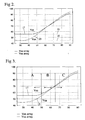
- Figure 2 depicts the relative performance in varying background noise of two different microphone array processors.
- Figure 3 depicts three regions of the graph shown in Figure 2.
- Figure 4 depicts the present invention according to a second embodiment.
- Figure 5 depicts the present invention according to a third embodiment.
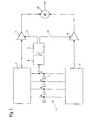
- a microphone array 1 consisting of a number of microphones. In the present example four microphones are shown however other numbers are also possible and the invention is not limited to the number of microphones used herein.
- the outputs of the microphones are labelled from A to D. According to a first embodiment the microphone outputs are passed to two different signal processing modules named Yss and Ysa and denoted as items 2 and 4 respectively.
- processors Although in the present example only two processors are shown it is possible to have a greater number of processors in which case selection between them is also made according to the criteria explained herein.
- the invention may be embodied by means of a single processor configurable into two or more modes. In that case selection between processing modes is also made according to the criteria explained herein.
- the first signal processing module Yss 2 is characterised by having a greater directionality but also a lower ratio of signal to internal noise.
- the second signal processing module Ysa has a higher ratio of signal to internal noise and a lower degree of directionality.
- noise floor indicating circuit 8 One of the microphones 3 of the array is monitored and its output passed to a noise floor indicating circuit 8.
- a simple noise floor indicating circuit typically consists of an AC coupling capacitor followed by a rectifier and low pass filter.
- the noise floor usually has a magnitude similar to the signal envelope, monitoring of the envelope provides an indication of the noise floor subsequent to appropriate scaling.
- the output of the noise floor detector comprises a relatively slowly moving DC signal indicative of the ambient noise floor.
- the DC signal from the noise floor indicator is coupled to control circuit 5.
- Emanating from control circuit 5 are two control lines 11 and 11'.
- Control circuit 5 contains an inverting amplifier which is connected between the output from the noise floor detector 8 and control line 11'. It also contains a buffer amplifier or depending on the remainder of the circuitry used a conductor, connected between the output of the noise floor detector 8 and control line 11.
- Control line 11' is connected to voltage controlled amplifier 9 which is also connected to the output of Ysa, 4.
- Contol line 11 is similarly connected to voltage controlled amplifier 7 which is also connected to the output of Yss, 2.
- VCA 7 and VCA 9 are added together by summer 16, which may consist of an appropriately configured operational amplifier, and then passed to a conventional hearing aid device (not shown).
- Figure 2 illustrates the noise discrimination ability for the subtractive 2 and additive 4 processors.
- the Figure depicts the characteristic outputs of Ysa and Yss in dB's on the vertical axis plotted againsT ambient acoustic noise floor, in dBs on the horizontal axis. It will be noted that as the ambient noise falls to low values, depicted as region A of Figure 3, the output of Yss 2 and Ysa 4 are substantially due to electrical noise internally generated in the processors and microphone array. A lower processor output for a given noise floor level indicates a higher directivity and hence better sound discrimination ability.
- the noise floor detector 8, control circuit 5 and VCA's 7, 9 are scaled so that as the noise floor indicative signal drops VCA 7 attenuates whilst the gain of VCA 9 increases so that the output of summer 16 is substantially Ysa, which is appropriate for the low noise environment.
- the second order subtractive processor Yss becomes preferred and so by the design of the device in Figure 1 VCA 7 increases its gain whilst that of VCA 9 is attenuated, the output of summer 16 becoming substantially that of Yss.
- FIG. 3 there is depicted a version of Figure 2 wherein the acoustic ambient noise has been demarcated into three ranges A, B and C.
- VCA's 7 and 9 are controlled by the noise floor detector 8 so that the output of the summer 16 predominantly consists of the output of the processor which provides the lowest total noise output. Consequently, in region A of the graph the output of the summer consists entirely of signal from Ysa 4. In region B of the graph the output of the summer consists of a mixture of both processors. Leftward of the point at which the curves 17, 18 characteristic of each of the processors intersect the summer output is increasingly Ysa 4. Rightward of the intersection point it is increasingly Yss 2. At the point of intersection it is equally due to signal from Ysa and Yss. In region C of the graph the output of the summer consists entirely of signal from Yss.
- the system is calibrated for switchover by noting the output from the noise floor detector at which the intersection of curves 17 and 18 occurs.
- the VCA's are then adjusted so that complete switchover from one processor to the other takes place within a cross-over range centred on the intersection point.
- a cross-over range a little greater than 6dB is required in order to minimise the subject's perception of the change in processing strategies.
- the blending of the two signals which occurs in cross-over range B is not essential to the invention, it makes the device more comfortable for the subject by reducing the perception of the switching between processing strategies. Consequently the invention could be implemented by automatically switching between the two strategies at the point where their characteristic processor curves intersect rather than blending the output of the two processors across cross-over range B.
- hysteresis could be introduced into the switching or blending operation so that switch over would occur at different values of extemal noise depending on whether the extemal noise was increasing or decreasing.
- an auto switching arrangement comprising processor microphone array processor Yn, signal detector circuit 40 and sample-and-hold (S/H) circuits 41 and 42 is provided.
- the S/H circuits contain magnitude estimator circuits, to receive signal from Ysa 4 and Yss 2, comprising a rectifier and low pass filter to generate a rectified and time averaged value indicative of the magnitude of the signal emanating from Ysa and Yss.
- the S/H circuits are under command of on-beam signal detector 43 from which they take a control signal which determines whether they are to sample signal derived from Ysa and Yss, or to hold.
- the auto switch-over system automatically chooses the most appropriate proportions of output of array processors Yss 2 and Ysa 4 in order to maximise the ratio of desired signal to undesired ambient noise.
- the ambient noise output by the processors is a combination of acoustic ambient noise and electrical noise emanating from the processors and microphone array.
- On-beam signal detector 40 takes two inputs.
- a first input emanates from processor Yn 43.
- Processor 43 is a microphone array processor whose output is minimally sensitive to the on-beam signal that processors Ysa and Yss are designed to maximise. For example if the device of Figure 4 were to be used in a crowded room, including people speaking and other sound sources, then whilst Ysa and Yss are designed to optimise the signal coming from a particular direction relative to the microphone array, and minimise the remaining noise, Yn, in contrast generates an output that monitors the remaining noise.
- the inventors have found that a processor constructed similarly to Ysa or Yss except having maximum sensitivity in a direction opposite to the desired on-beam direction of Yss and Ysa, is suitable for this purpose.
- the second input to signal detector 40 emanates from the output of summer 16 which is a combination of signals from Yss 2 and Ysa 4.
- Signal detector 40 takes the signal from Yn 43 and produces an estimate of its average value over a short period of time, this may be done by rectifying the signal and then low pass filtering it as was described in respect of noise floor indicating circuit 8 of Figure 1.
- Signal detector 40 also processes the signal from summer 16 in a similar manner. The two rectified and averaged signals are then compared to produce their difference being the processed signal from Yn 43 minus the processed signal from summer 16. The difference signal is passed through a comparator. The comparator produces a logic high detect signal in the event that the difference signal is positive and a logic low detect signal in the event that it is less than or equal to zero.
- signal detector 40 will generate a logic low signal which will indicate that the output of summer 16 contains signal other than ambient noise. Conversely, if the signal coming from processor Yn 43 is of greater magnitude than the signal from summer 16 then signal detector 43 will generate a logic high output to indicate that the output of summer 16 does not contain signal of interest.
- the detect signal will be high.
- S/H circuit 41 will track signal from Yss 2 while signal from Ysa 4 will be tracked by S/H circuit 42.
- the outputs of S/H circuits 41 and 42 will be approximately the same as those from processors Yss 2 and Ysa 4. Accordingly, when the ambient noise level is low, i.e. the processors are operating in region A of Figure 3, then the output of S/H circuit 41 will be greater than the output of S/H circuit 42. Consequently, the output of differential amplifier 39 will be negative so that the gain of VCA 7 will be low relative to the gain of VCA 9.
- control signal for VCA 9 is passed through inverter 10 so that it is of opposite polarity to that which controls VCA 7.
- the output of summer 16 will be predominantly signal from Ysa 4 which, as can be seen from Figure 3, is of markedly lower noise in Region A than that of Yss 4.
- FIG. 5 there is depicted an embodiment of the present invention as applied to a constrained supergain array processor.
- a constrained supergain array processor conventionally consists of a series of microphones 51-54 spaced less than one half wavelength, of the centre frequency of the band to be processed, apart.
- the outputs of each microphone are each multiplied by a complex weight z1..z4, by complex multipliers 61-64.
- This operation is most conveniently performed using digital techniques and so, prior to multiplication, the signals are passed through anti-aliasing filters 71-74 and converted to digital signals by ADC's 81-84 according to standard methods.
- noise level processor Yn 56 and allocation means are provided to alter the weights z1..z4.
- Processor Yn generates an estimate of the ambient acoustic noise level. This estimate is sent to look up table 58 which contains a list of precalculated values for z1..z4 for given values of ambient acoustic noise level. Calculation of the weighting values is described in the formerly referenced paper by Cox et al.
- look up table it is possible to instead calculate the values for the weights as required.
- the allocation means would not consist of look-up table 58 but instead would be replaced by calculations undertaken in a central digital signal processor or alternatively by a suitable co-processor.
- the weighted digital signals are combined, shown schematically by summer 66, and the resulting signal optionally converted to an analog signal by DAC and associated anti-imaging filtering 68.
Landscapes
- Health & Medical Sciences (AREA)
- General Health & Medical Sciences (AREA)
- Neurosurgery (AREA)
- Otolaryngology (AREA)
- Physics & Mathematics (AREA)
- Engineering & Computer Science (AREA)
- Acoustics & Sound (AREA)
- Signal Processing (AREA)
- Circuit For Audible Band Transducer (AREA)
- Soundproofing, Sound Blocking, And Sound Damping (AREA)
Applications Claiming Priority (3)
| Application Number | Priority Date | Filing Date | Title |
|---|---|---|---|
| AUPO714197 | 1997-06-02 | ||
| AUPO7141A AUPO714197A0 (en) | 1997-06-02 | 1997-06-02 | Multi-strategy array processor |
| AUPO7141/97 | 1997-06-02 |
Publications (2)
| Publication Number | Publication Date |
|---|---|
| EP0883325A2 true EP0883325A2 (de) | 1998-12-09 |
| EP0883325A3 EP0883325A3 (de) | 2000-12-27 |
Family
ID=3801432
Family Applications (1)
| Application Number | Title | Priority Date | Filing Date |
|---|---|---|---|
| EP98304349A Withdrawn EP0883325A3 (de) | 1997-06-02 | 1998-06-02 | Multi-strategie Arrayprozessor |
Country Status (3)
| Country | Link |
|---|---|
| US (1) | US6603858B1 (de) |
| EP (1) | EP0883325A3 (de) |
| AU (1) | AUPO714197A0 (de) |
Cited By (12)
| Publication number | Priority date | Publication date | Assignee | Title |
|---|---|---|---|---|
| US6394947B1 (en) | 1998-12-21 | 2002-05-28 | Cochlear Limited | Implantable hearing aid with tinnitus masker or noiser |
| WO2003015459A3 (en) * | 2001-08-10 | 2003-11-20 | Rasmussen Digital Aps | Sound processing system that exhibits arbitrary gradient response |
| WO2003098970A1 (en) * | 2002-05-21 | 2003-11-27 | Hearworks Pty Ltd | Programmable auditory prosthesis with trainable automatic adaptation to acoustic conditions |
| WO2003015457A3 (en) * | 2001-08-10 | 2004-03-11 | Rasmussen Digital Aps | Sound processing system including forward filter that exhibits arbitrary directivity and gradient response in single wave sound environment |
| WO2003036614A3 (en) * | 2001-09-12 | 2004-03-18 | Bitwave Private Ltd | System and apparatus for speech communication and speech recognition |
| US6999541B1 (en) | 1998-11-13 | 2006-02-14 | Bitwave Pte Ltd. | Signal processing apparatus and method |
| US7471799B2 (en) | 2001-06-28 | 2008-12-30 | Oticon A/S | Method for noise reduction and microphonearray for performing noise reduction |
| AU2004240216B2 (en) * | 2002-05-21 | 2009-01-15 | Sivantos Pte. Ltd. | Programmable Auditory Prosthesis with Trainable Automatic Adaptation to Acoustic Conditions |
| EP2226795A1 (de) | 2009-03-06 | 2010-09-08 | Siemens Medical Instruments Pte. Ltd. | Hörvorrichtung und Verfahren zum Reduzieren eines Störgeräuschs für eine Hörvorrichtung |
| US7889879B2 (en) | 2002-05-21 | 2011-02-15 | Cochlear Limited | Programmable auditory prosthesis with trainable automatic adaptation to acoustic conditions |
| EP1017253B1 (de) * | 1998-12-30 | 2012-10-31 | Siemens Corporation | Blind-Trennung von Signalquellen für Hörhilfegeräte |
| US8605923B2 (en) | 2007-06-20 | 2013-12-10 | Cochlear Limited | Optimizing operational control of a hearing prosthesis |
Families Citing this family (10)
| Publication number | Priority date | Publication date | Assignee | Title |
|---|---|---|---|---|
| US20060072768A1 (en) * | 1999-06-24 | 2006-04-06 | Schwartz Stephen R | Complementary-pair equalizer |
| WO2003032522A2 (en) * | 2001-10-08 | 2003-04-17 | Qinetiq Limited | Signal processing system and method for determininig antenna weights |
| US7623929B1 (en) | 2002-08-30 | 2009-11-24 | Advanced Bionics, Llc | Current sensing coil for cochlear implant data detection |
| US8285383B2 (en) * | 2005-07-08 | 2012-10-09 | Cochlear Limited | Directional sound processing in a cochlear implant |
| US7697827B2 (en) | 2005-10-17 | 2010-04-13 | Konicek Jeffrey C | User-friendlier interfaces for a camera |
| US8325964B2 (en) * | 2006-03-22 | 2012-12-04 | Dsp Group Ltd. | Method and system for bone conduction sound propagation |
| DE102006051071B4 (de) | 2006-10-30 | 2010-12-16 | Siemens Audiologische Technik Gmbh | Pegelabhängige Geräuschreduktion |
| JP6017854B2 (ja) * | 2011-06-24 | 2016-11-02 | 本田技研工業株式会社 | 情報処理装置、情報処理システム、情報処理方法及び情報処理プログラム |
| CN105142090B (zh) * | 2015-08-24 | 2018-04-13 | 歌尔股份有限公司 | 确定本底噪声测试用供电电源的纹波系数的方法及系统 |
| CN112201267B (zh) * | 2020-09-07 | 2024-09-20 | 北京达佳互联信息技术有限公司 | 一种音频处理方法、装置、电子设备及存储介质 |
Family Cites Families (23)
| Publication number | Priority date | Publication date | Assignee | Title |
|---|---|---|---|---|
| US3783192A (en) | 1971-12-30 | 1974-01-01 | Sansui Electric Co | Decoder for use in matrix four-channel system |
| GB1458663A (en) | 1972-12-15 | 1976-12-15 | Ard Anstalt | Microphone circuits |
| JPS5712999B2 (de) | 1974-04-08 | 1982-03-13 | ||
| US4334740A (en) | 1978-09-12 | 1982-06-15 | Polaroid Corporation | Receiving system having pre-selected directional response |
| DE3102208C2 (de) | 1980-01-25 | 1983-01-05 | Victor Company Of Japan, Ltd., Yokohama, Kanagawa | Mikrofonsystem mit veränderbarer Richtcharakteristik |
| US4412097A (en) | 1980-01-28 | 1983-10-25 | Victor Company Of Japan, Ltd. | Variable-directivity microphone device |
| US4498060A (en) | 1981-12-01 | 1985-02-05 | Dolby Ray Milton | Circuit arrangements for modifying dynamic range using series arranged bi-linear circuits |
| JPS5933357U (ja) | 1982-08-27 | 1984-03-01 | パイオニア株式会社 | 圧縮伸長装置 |
| US4536887A (en) * | 1982-10-18 | 1985-08-20 | Nippon Telegraph & Telephone Public Corporation | Microphone-array apparatus and method for extracting desired signal |
| US4898179A (en) | 1985-06-17 | 1990-02-06 | Vladimir Sirota | Device for detecting, monitoring, displaying and recording of material and fetal vital signs and permitting communication between a woman and her fetus |
| DE8529437U1 (de) | 1985-10-16 | 1987-06-11 | Siemens AG, 1000 Berlin und 8000 München | Richtmikrofon |
| US4802227A (en) * | 1987-04-03 | 1989-01-31 | American Telephone And Telegraph Company | Noise reduction processing arrangement for microphone arrays |
| US4931977A (en) * | 1987-10-30 | 1990-06-05 | Canadian Marconi Company | Vectorial adaptive filtering apparatus with convergence rate independent of signal parameters |
| DK159357C (da) | 1988-03-18 | 1991-03-04 | Oticon As | Hoereapparat, navnlig til anbringelse i oeret |
| US4956867A (en) * | 1989-04-20 | 1990-09-11 | Massachusetts Institute Of Technology | Adaptive beamforming for noise reduction |
| US5033082A (en) | 1989-07-31 | 1991-07-16 | Nelson Industries, Inc. | Communication system with active noise cancellation |
| AT407815B (de) | 1990-07-13 | 2001-06-25 | Viennatone Gmbh | Hörgerät |
| US5548681A (en) * | 1991-08-13 | 1996-08-20 | Kabushiki Kaisha Toshiba | Speech dialogue system for realizing improved communication between user and system |
| US5574824A (en) * | 1994-04-11 | 1996-11-12 | The United States Of America As Represented By The Secretary Of The Air Force | Analysis/synthesis-based microphone array speech enhancer with variable signal distortion |
| SE502888C2 (sv) | 1994-06-14 | 1996-02-12 | Volvo Ab | Adaptiv mikrofonanordning och förfarande för adaptering till en inkommande målbrussignal |
| AUPM900594A0 (en) | 1994-10-24 | 1994-11-17 | Cochlear Pty. Limited | Automatic sensitivity control |
| GB2306086A (en) | 1995-10-06 | 1997-04-23 | Richard Morris Trim | Improved adaptive audio systems |
| US5673327A (en) * | 1996-03-04 | 1997-09-30 | Julstrom; Stephen D. | Microphone mixer |
-
1997
- 1997-06-02 AU AUPO7141A patent/AUPO714197A0/en not_active Abandoned
-
1998
- 1998-06-01 US US09/088,694 patent/US6603858B1/en not_active Expired - Fee Related
- 1998-06-02 EP EP98304349A patent/EP0883325A3/de not_active Withdrawn
Cited By (17)
| Publication number | Priority date | Publication date | Assignee | Title |
|---|---|---|---|---|
| US6999541B1 (en) | 1998-11-13 | 2006-02-14 | Bitwave Pte Ltd. | Signal processing apparatus and method |
| US7289586B2 (en) | 1998-11-13 | 2007-10-30 | Bitwave Pte Ltd. | Signal processing apparatus and method |
| US6394947B1 (en) | 1998-12-21 | 2002-05-28 | Cochlear Limited | Implantable hearing aid with tinnitus masker or noiser |
| EP1017253B1 (de) * | 1998-12-30 | 2012-10-31 | Siemens Corporation | Blind-Trennung von Signalquellen für Hörhilfegeräte |
| US7471799B2 (en) | 2001-06-28 | 2008-12-30 | Oticon A/S | Method for noise reduction and microphonearray for performing noise reduction |
| WO2003015459A3 (en) * | 2001-08-10 | 2003-11-20 | Rasmussen Digital Aps | Sound processing system that exhibits arbitrary gradient response |
| WO2003015457A3 (en) * | 2001-08-10 | 2004-03-11 | Rasmussen Digital Aps | Sound processing system including forward filter that exhibits arbitrary directivity and gradient response in single wave sound environment |
| US7274794B1 (en) | 2001-08-10 | 2007-09-25 | Sonic Innovations, Inc. | Sound processing system including forward filter that exhibits arbitrary directivity and gradient response in single wave sound environment |
| US7346175B2 (en) | 2001-09-12 | 2008-03-18 | Bitwave Private Limited | System and apparatus for speech communication and speech recognition |
| WO2003036614A3 (en) * | 2001-09-12 | 2004-03-18 | Bitwave Private Ltd | System and apparatus for speech communication and speech recognition |
| AU2004240216B2 (en) * | 2002-05-21 | 2009-01-15 | Sivantos Pte. Ltd. | Programmable Auditory Prosthesis with Trainable Automatic Adaptation to Acoustic Conditions |
| US7889879B2 (en) | 2002-05-21 | 2011-02-15 | Cochlear Limited | Programmable auditory prosthesis with trainable automatic adaptation to acoustic conditions |
| WO2003098970A1 (en) * | 2002-05-21 | 2003-11-27 | Hearworks Pty Ltd | Programmable auditory prosthesis with trainable automatic adaptation to acoustic conditions |
| US8532317B2 (en) | 2002-05-21 | 2013-09-10 | Hearworks Pty Limited | Programmable auditory prosthesis with trainable automatic adaptation to acoustic conditions |
| US8605923B2 (en) | 2007-06-20 | 2013-12-10 | Cochlear Limited | Optimizing operational control of a hearing prosthesis |
| EP2226795A1 (de) | 2009-03-06 | 2010-09-08 | Siemens Medical Instruments Pte. Ltd. | Hörvorrichtung und Verfahren zum Reduzieren eines Störgeräuschs für eine Hörvorrichtung |
| US8600087B2 (en) | 2009-03-06 | 2013-12-03 | Siemens Medical Instruments Pte. Ltd. | Hearing apparatus and method for reducing an interference noise for a hearing apparatus |
Also Published As
| Publication number | Publication date |
|---|---|
| AUPO714197A0 (en) | 1997-06-26 |
| EP0883325A3 (de) | 2000-12-27 |
| US6603858B1 (en) | 2003-08-05 |
Similar Documents
| Publication | Publication Date | Title |
|---|---|---|
| US6603858B1 (en) | Multi-strategy array processor | |
| EP2238592B1 (de) | Verfahren zur verringerung von rauschen in einem eingangssignal eines hörgeräts sowie ein hörgerät | |
| US6888949B1 (en) | Hearing aid with adaptive noise canceller | |
| JP3986436B2 (ja) | 入力トランスデューサの適応整合を有する補聴器 | |
| US6704422B1 (en) | Method for controlling the directionality of the sound receiving characteristic of a hearing aid a hearing aid for carrying out the method | |
| EP1380187B1 (de) | Richtungssteuerung und verfahren zur steuerung eines hörgeräts | |
| EP0740893B1 (de) | Dynamic-intensity-strahlformungssystem zur geräuschverminderung in einem binauralen hörhilfegerät | |
| US8068627B2 (en) | System for automatic reception enhancement of hearing assistance devices | |
| US7876918B2 (en) | Method and device for processing an acoustic signal | |
| EP1695590B1 (de) | Verfahren und vorrichtung zum erzeugen adaptiver richtungssignale | |
| US20080044046A1 (en) | Hearing aid with directional microphone system, and method for operating a hearing aid | |
| CA2479675C (en) | Directional controller for a hearing aid | |
| US8199949B2 (en) | Processing an input signal in a hearing aid | |
| EP3185587B1 (de) | Hörgerät mit unterdrückung von schallimpulsen | |
| EP3008924B1 (de) | Verfahren der signalverarbeitung in einem hörgerät und hörgerätensystem | |
| WO2025068818A1 (en) | Hearing aid with own-voice mitigation | |
| US10692514B2 (en) | Single channel noise reduction | |
| EP4156711B1 (de) | Audiovorrichtung mit doppelter strahlformung | |
| EP4156182A1 (de) | Audiovorrichtung mit distraktordämpfer | |
| EP4156183B1 (de) | Audiovorrichtung mit mehreren dämpfungsgliedern | |
| EP1203508B1 (de) | EINE METHODE ZUR REGELUNG DER RICHTWIRKUNG DER SCHALLEMPFANGSCHARAkTERISTIK EINES HÖRGERÄTES UND EIN HÖRGERÄT ZUR AUSFÜHRUNG DER METHODE | |
| EP4156719A1 (de) | Audiovorrichtung mit mikrofonempfindlichkeitskompensator | |
| WO2026064373A1 (en) | Noise reduction followed by wide dynamic range compression in ear-worn devices | |
| AU2004310722B2 (en) | Method and apparatus for producing adaptive directional signals |
Legal Events
| Date | Code | Title | Description |
|---|---|---|---|
| PUAI | Public reference made under article 153(3) epc to a published international application that has entered the european phase |
Free format text: ORIGINAL CODE: 0009012 |
|
| AK | Designated contracting states |
Kind code of ref document: A2 Designated state(s): CH DE DK LI |
|
| AX | Request for extension of the european patent |
Free format text: AL;LT;LV;MK;RO;SI |
|
| PUAL | Search report despatched |
Free format text: ORIGINAL CODE: 0009013 |
|
| AK | Designated contracting states |
Kind code of ref document: A3 Designated state(s): AT BE CH CY DE DK ES FI FR GB GR IE IT LI LU MC NL PT SE |
|
| AX | Request for extension of the european patent |
Free format text: AL;LT;LV;MK;RO;SI |
|
| 17P | Request for examination filed |
Effective date: 20010625 |
|
| AKX | Designation fees paid |
Free format text: CH DE DK LI |
|
| 17Q | First examination report despatched |
Effective date: 20031007 |
|
| STAA | Information on the status of an ep patent application or granted ep patent |
Free format text: STATUS: THE APPLICATION IS DEEMED TO BE WITHDRAWN |
|
| 18D | Application deemed to be withdrawn |
Effective date: 20040419 |