EP0883444B1 - Methode et systeme de distribution de solution visqueuse - Google Patents
Methode et systeme de distribution de solution visqueuse Download PDFInfo
- Publication number
- EP0883444B1 EP0883444B1 EP97905549A EP97905549A EP0883444B1 EP 0883444 B1 EP0883444 B1 EP 0883444B1 EP 97905549 A EP97905549 A EP 97905549A EP 97905549 A EP97905549 A EP 97905549A EP 0883444 B1 EP0883444 B1 EP 0883444B1
- Authority
- EP
- European Patent Office
- Prior art keywords
- pressure
- dosing unit
- flow
- value
- regulator
- Prior art date
- Legal status (The legal status is an assumption and is not a legal conclusion. Google has not performed a legal analysis and makes no representation as to the accuracy of the status listed.)
- Expired - Lifetime
Links
- 238000000034 method Methods 0.000 title claims abstract description 22
- 239000000463 material Substances 0.000 claims abstract description 128
- 239000011345 viscous material Substances 0.000 claims abstract description 13
- 238000012360 testing method Methods 0.000 claims description 14
- 238000010438 heat treatment Methods 0.000 claims description 10
- 230000001105 regulatory effect Effects 0.000 claims description 8
- 238000003032 molecular docking Methods 0.000 claims description 7
- 230000033228 biological regulation Effects 0.000 claims description 5
- 239000000126 substance Substances 0.000 claims description 5
- 230000001276 controlling effect Effects 0.000 claims description 3
- 238000007789 sealing Methods 0.000 description 7
- 239000003292 glue Substances 0.000 description 5
- 150000001875 compounds Chemical class 0.000 description 4
- 238000007667 floating Methods 0.000 description 4
- 238000005259 measurement Methods 0.000 description 4
- 230000008569 process Effects 0.000 description 4
- 230000004044 response Effects 0.000 description 4
- 238000010586 diagram Methods 0.000 description 3
- 230000006870 function Effects 0.000 description 3
- 239000007788 liquid Substances 0.000 description 3
- 229910000831 Steel Inorganic materials 0.000 description 2
- 238000004026 adhesive bonding Methods 0.000 description 2
- 230000008859 change Effects 0.000 description 2
- 230000008878 coupling Effects 0.000 description 2
- 238000010168 coupling process Methods 0.000 description 2
- 238000005859 coupling reaction Methods 0.000 description 2
- 238000005070 sampling Methods 0.000 description 2
- 239000010959 steel Substances 0.000 description 2
- 239000004593 Epoxy Substances 0.000 description 1
- 239000000853 adhesive Substances 0.000 description 1
- 230000001070 adhesive effect Effects 0.000 description 1
- 230000003321 amplification Effects 0.000 description 1
- 125000000484 butyl group Chemical group [H]C([*])([H])C([H])([H])C([H])([H])C([H])([H])[H] 0.000 description 1
- 238000006243 chemical reaction Methods 0.000 description 1
- 238000004939 coking Methods 0.000 description 1
- 230000006835 compression Effects 0.000 description 1
- 238000007906 compression Methods 0.000 description 1
- 238000010276 construction Methods 0.000 description 1
- 238000007796 conventional method Methods 0.000 description 1
- 239000002826 coolant Substances 0.000 description 1
- 238000012937 correction Methods 0.000 description 1
- 230000007423 decrease Effects 0.000 description 1
- 238000001514 detection method Methods 0.000 description 1
- 230000006866 deterioration Effects 0.000 description 1
- 230000000694 effects Effects 0.000 description 1
- 230000008030 elimination Effects 0.000 description 1
- 238000003379 elimination reaction Methods 0.000 description 1
- 239000000945 filler Substances 0.000 description 1
- 239000012530 fluid Substances 0.000 description 1
- 239000004519 grease Substances 0.000 description 1
- 238000005461 lubrication Methods 0.000 description 1
- 238000012423 maintenance Methods 0.000 description 1
- 238000004519 manufacturing process Methods 0.000 description 1
- 230000007246 mechanism Effects 0.000 description 1
- 239000000155 melt Substances 0.000 description 1
- 238000012986 modification Methods 0.000 description 1
- 230000004048 modification Effects 0.000 description 1
- 238000003199 nucleic acid amplification method Methods 0.000 description 1
- 239000003921 oil Substances 0.000 description 1
- 239000003973 paint Substances 0.000 description 1
- 239000004033 plastic Substances 0.000 description 1
- 229920003023 plastic Polymers 0.000 description 1
- 229920002635 polyurethane Polymers 0.000 description 1
- 239000004814 polyurethane Substances 0.000 description 1
- 239000004800 polyvinyl chloride Substances 0.000 description 1
- 238000012545 processing Methods 0.000 description 1
- 230000001681 protective effect Effects 0.000 description 1
- 239000004065 semiconductor Substances 0.000 description 1
- 230000035945 sensitivity Effects 0.000 description 1
- 239000010703 silicon Substances 0.000 description 1
- 229910052710 silicon Inorganic materials 0.000 description 1
- 239000007787 solid Substances 0.000 description 1
- 239000002904 solvent Substances 0.000 description 1
- 230000000007 visual effect Effects 0.000 description 1
Images


Classifications
-
- B—PERFORMING OPERATIONS; TRANSPORTING
- B05—SPRAYING OR ATOMISING IN GENERAL; APPLYING FLUENT MATERIALS TO SURFACES, IN GENERAL
- B05C—APPARATUS FOR APPLYING FLUENT MATERIALS TO SURFACES, IN GENERAL
- B05C11/00—Component parts, details or accessories not specifically provided for in groups B05C1/00 - B05C9/00
- B05C11/10—Storage, supply or control of liquid or other fluent material; Recovery of excess liquid or other fluent material
- B05C11/1002—Means for controlling supply, i.e. flow or pressure, of liquid or other fluent material to the applying apparatus, e.g. valves
- B05C11/1034—Means for controlling supply, i.e. flow or pressure, of liquid or other fluent material to the applying apparatus, e.g. valves specially designed for conducting intermittent application of small quantities, e.g. drops, of coating material
-
- B—PERFORMING OPERATIONS; TRANSPORTING
- B05—SPRAYING OR ATOMISING IN GENERAL; APPLYING FLUENT MATERIALS TO SURFACES, IN GENERAL
- B05C—APPARATUS FOR APPLYING FLUENT MATERIALS TO SURFACES, IN GENERAL
- B05C11/00—Component parts, details or accessories not specifically provided for in groups B05C1/00 - B05C9/00
- B05C11/10—Storage, supply or control of liquid or other fluent material; Recovery of excess liquid or other fluent material
- B05C11/1047—Apparatus or installations for supplying liquid or other fluent material comprising a buffer container or an accumulator between the supply source and the applicator
-
- G—PHYSICS
- G05—CONTROLLING; REGULATING
- G05D—SYSTEMS FOR CONTROLLING OR REGULATING NON-ELECTRIC VARIABLES
- G05D7/00—Control of flow
- G05D7/06—Control of flow characterised by the use of electric means
- G05D7/0617—Control of flow characterised by the use of electric means specially adapted for fluid materials
- G05D7/0629—Control of flow characterised by the use of electric means specially adapted for fluid materials characterised by the type of regulator means
- G05D7/0676—Control of flow characterised by the use of electric means specially adapted for fluid materials characterised by the type of regulator means by action on flow sources
Definitions
- the present invention refers to a method and a system essentially for dynamic flow control when dispensing a substantially viscous material by means of a dosing system, including at least one dosing unit controlled by means of a computer unit, which dosing unit consists of at least a pressure part and a material container for holding the material to be applied, a nozzle and a pressure member displaceable in the material container.
- the invention also refers to a method for elimination of the dosage interrupt when dispensing a substantially viscous material by means of a dosing system.
- sealing compounds and glue are used, which in floating form are applied onto at least one surface of the workpiece, which must be sealed or joined.
- the material that is used for usually sealing/gluing contains chemicals and substances, which are directly or indirectly unhealthy for the people through contact or inhalation.
- protective clothing which makes working difficult.
- glue in solid form it is needed that the glue melts and is applied in floating form, which requires that the dosing unit is equipped with heating element, which in turn requires heavier and bulkier apparatus.
- a dosing unit is arranged on a robot arm which moves over the workpiece to be furnished with the viscous material.
- the robot arm controlled by a computer moves in accordance with programmed instructions and dispenses, for example the glue or the sealing compound by applying strings of material on the contemplated areas.
- Dosing systems are commercially available where a doser is arranged on a robot arm. Nearby is arranged a docking/pump station, where that viscous material to be dispensed is kept. During the operation, the robot docks the doser in the docking station and fills it with the viscous material. The amount of the material varies in respect of the size of the dosing unit. Subsequently, the robot arm is moved over the workpiece and the material is applied on the same.
- Typical application temperatures are between +15 ° and +150 ° C, preferably 30°, 70°, 140° C, where a small temperature deviation results in a significant change of viscosity. Tests of certain material have shown that, for example 2 ° lower temperature results in 12% lower flow and 5 ° results in 26% lower flow.
- the characteristics of the materials can be changed depending on how the material is handled, e.g. if the material rests a long time in the dosing unit, it becomes more viscous.
- WO 88/07713 discloses a method and device, mountable on a robot arm, for dispensing material in floating form, which is dosed from a nozzle in an amount which is controlled by means of a measuring valve including a seat and a pin connected to a double-acting piston, which can be moved relative the seat and modulate material flow.
- a servo actuator connected to a feedback, controls and positions the piston and the pin relative the seat with a control signal, generated with regard to difference between an operation signal which presents the set flow and the sum of a pair of feedback signals, one of which shows the actual flow amount while the other corresponds to both the relative speed and position of the pin in respect of the seat.
- the device uses a so-called position dependant movement feedback and the principle is based on flow limiting with variable area, where the relationship between the adjustment sensitivity increases with increasing area between the valve pin and the seat.
- the increasing area is obtained by adjusting with small distances between the pin and the seat and in this way obtaining large variables in the flow area.
- the positions of the double-acting piston and the pin are fed back to a control circuit by means of an electromagnetic inductance circuit.
- a flow sensor is located at the nozzle which generates a first flow signal, as the first feedback signal to the control system.
- the first feedback signal is generated by a measured signal based on the pressure drop over the nozzle.
- Another position dependant fed back signal is generated in respect of the position of the pin and feedback to the control system.
- US 4,666,732 discloses a process for the regulation or control of the flow of a viscous liquid, such as an adhesive or plastic substance, which is applied as seam on a workpiece by an applicator device guided by a robot, whereby the viscous liquid of the applicator device is continuously supplied from a cylinder in which a piston, shiftable by a drive mechanism exerts a constant pressure on the liquid.
- the path is measured which is passed by the piston during the time in which the robot passes through a certain track section.
- the system according to this document does not run a test sequence; data are collected during normal application sequences.
- the system has the drawback of failure during the application, which can result in damages to the workpiece.
- the object of the present invention is to provide a dosing system which is free from above-mentioned drawbacks.
- Another object of the invention is to provide a flow control system with an "off-line" measuring system and minimum response time from the doser to the adjusted flow.
- the system should also comply with the preciseness for the flow control, i.e. inaccuracy ⁇ 1.5% and a response time of about 0.1 between the maximum and minimum flow.
- the system will reduce the pressure drop in the feed hoses and pipe line systems.
- a main object of the system, according to the present invention is that it will be reliable, thanks to that the system will be able to detect feed interruption when dispensing the viscous material. Moreover, the system will be made of parts existing on the market, which reduces the cost of production.
- Fig. 1 shows schematically a first embodiment of a preferred dosing system 10, according to the invention.
- the system substantially includes at least one docking station I I, a pump station 12 and a dosing unit 13 and a control arrangement 14 (marked with dashed line) and a robot (not shown).
- the dosing unit 13 consists of a hollow housing 19, substantially including a first and a second variable chamber 20 and 21, respectively, and a material container 22.
- the housing is also provided with an inlet/outlet 23 for a pressure media, such as compressed air and a combined inlet/outlet 24, via a nozzle for charge and dosage of material.
- a pressure media such as compressed air
- a combined inlet/outlet 24 via a nozzle for charge and dosage of material.
- the control awangement 14 includes means for controlling and regulating the flow from the dosing unit 13, and according to this embodiment comprises at least a microprocessor-based control unit 15, a regulator 16 and valves 17 and 18, respectively.
- the control unit 15 can further include a number of memory units for storing data and instructions.
- the control unit 15 may be controlled by the robot or another external control unit According to this embodiment, the input 151 is connected to a set value indicator (not shown), via input 152, the control unit is controlled from the robot, output 153 is connected to the regulator 16 and transmits control signals to it, input 154 is a P/I feedback coupling from the regulator 16, the input 155 is connected to the potentiometer 26 through which the value of the potentiometer is read, input 156 is connected to the temperature indicator 29 for reading its value and the output 157 is connected to the heating element 28 for controlling the same.
- the regulator 16 preferably consists of a conventional electromagnetic proportional regulator having a short response time ( ⁇ 30 milliseconds), connected via an analogous or digital set value input 161 to the control unit, via the output 162, an analogous or digital value is sent to the control unit 15, so-called P/I feedback, as a receipt to the set value; via output 163 the regulator 27 is controlled and via input 164 so-called P-air is connected.
- the regulator 27 is preferably a material pressure regulator with a mounted air servo. The material pressure regulator is used to regulate the material flow and can operate in a wide pressure range, for example from 1 up to 300 bar.
- the regulator is provided with variable spring assembly so that it can be adapted to different adjustment ranges.
- the material pressure regulator 27 compensates for variations in the characteristics of the material, and where it does not reign, the control unit 15 and the regulator 16 also regulates/compensates.
- the valve 17 is controlled directly from the control unit, output 158, and can supply the dosing unit with a constant compressed air.
- the pump system 12 supplies the docking station 11 with material (hot or cold), which afterwards is docked with the robot carried dosing unit 13.
- the dosing unit 13 is filled through the nozzle 24 and further through the material pressure regulator 27 which in the filling sequence is hold in open position by the analogously or digitally controlled servo pneumatic proportional pressure regulator 16.
- the regulator 27 After filling, the regulator 27 is closed, which in this position also functions as a stop valve.
- the dosing unit 13 is then pressurised afterwards with a fixed pressure suitable for a test sequence.
- a material compression is obtained.
- a test is carried out first.
- the dosing unit 13 is tested with an air free material and the value from the potentiometer 26 is registered. Then air in material can be detected before the dispensing is initiated and appropriate alarm can be given to the robot. The robot can then go to a position and signal to empty the material in an appropriate container.
- the set flow signal When dispensing, the set flow signal is received which is given from the robot in the control unit 15, as an analogous (0-10 volt) or a digital value.
- the control unit 15 converts the signal to an analogous value by means of a conversion factor, which depends on the size of the set flow.
- the conversion factor is obtained when the current material is fed out with fixed pressure values to the air pressure regulated servo regulator 16, subsequently the outputted volume is measured in respect of a fixed time constant.
- the process is re-run with an increased pressure over the regulator etc.
- Conversion factors for low, normal and high flow constants recalculate the set flow signal 151 from the robot to a suitable value for selected analogous proportional valve 16. Then the PI converter of the proportional regulator 16 confirms that the pressure coincides with the factor chosen by the control system.
- the dispensing is initiated as a direct value of the set flow signal 151, either as a fixed value or as a value directly proportional to the speed of the robot, so-called "TCP value”.
- the processing unit (processor) of the control unit 15 can sample via an A/D/A module (Analogous/Digital/Analogous module) the changes continuously on the feedback value 155 from the linear potentiometer 26. Differences in dispensing speed with regard to the received set value are detected by the processor, which by means of built-in regulators, so-called PID regulator adjusts the control signal 153 to the proportional regulator 16, with a pressure air value of for example 0-6 bar.
- A/D/A module Analogous/Digital/Analogous module
- the system can also be arranged with visual or audible alarm.
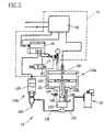
- Fig. 3 shows an embodiment of the system, according to the invention, where the dosing unit substantially differs from that in fig. I embodiment in that the dosing unit 113 is divided in two parts 113a and 113b. Both parts or only one of them, preferably part 113b, can be mounted on the robot arm.
- the dosing unit 113a essentially includes same parts as the dosing unit 13, according to fig. 1, i.e. the material container 122, the piston 125, the potentiometer 126, possible heating element 128 and sensor 129.
- the other part of the dosing unit 113b includes the nozzle 124 and the material pressure regulator 127.
- the material to be dispensed is supplied into the material container 122 from pump 12 via the pipe 131 and via a filling valve in the valve part 133 at the inlet to the material container 122. After filling, the pressure part 113a is pressurized with a constant pressure.
- the material pressure regulator 127 which in turn is controlled by the pressure air from the proportional valve 116.
- the adjustment and dosage are carried out analogous to the description of the first embodiment.
- the conduit 132 should be rigid or have large flow area to compensate for a possible pressure drop.
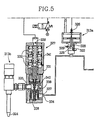
- Fig. 5 shows a preferred system where the material application regulator 327 is arranged between the dosing unit 313a and 313b.
- the dosing unit 313a includes essentially same parts as the dosing unit 213, according to fig. 3, i.e. the material container 322, piston 325, sensor 326, possible heating element 328 and sensor 329.
- the other part of the dosing unit 313b includes the nozzle 124.
- a control pin 341 is arranged in the center hole of the three pistons, whereby the control pressure presses the pistons 332 and thereby the control pin and via the ball holder the steel ball 337 away from the seat 338. Thereby the flow becomes proportionated by the relationship between the fed material pressure and the control pressure from the air-servo.
- the air servo can also be replaced with a spring set, whereby the wanted pressure in the secondary side is regulated by straining the spring set different hard and thereby obtaining a pressure value that corresponds to the wanted flow.
- the material pressure does not need to be constant.
- the value of the empty dosing unit is annotated by driving the piston in bottom, transferring the potentiometer value to the register and performing the same operation for full dosing unit
Landscapes
- Physics & Mathematics (AREA)
- General Physics & Mathematics (AREA)
- Engineering & Computer Science (AREA)
- Automation & Control Theory (AREA)
- Coating Apparatus (AREA)
- Sampling And Sample Adjustment (AREA)
- Application Of Or Painting With Fluid Materials (AREA)
Abstract
Claims (23)
- Procédé pour la commande d'écoulement dynamique lors de la distribution d'un matériel sensiblement visqueux par l'intermédiaire d'un système de dosage (10), comportant au moins une unité de dosage (13, 113, 213, 313) commandée par une unité de commande (15), laquelle unité de dosage comporte au moins une chambre de pression (20, 21, 120, 220), un conteneur de matériel (22, 122, 222, 322), pour contenir le matériel à appliquer, une buse (24, 124, 224, 324), un élément de pression (25, 125, 225, 325) pouvant être déplacé dans le conteneur de matériel (22, 122, 222, 322),
caractérisé par
les étapes consistant à :exécuter une séquence test avant une opération de distribution pour obtenir des données concernant la pression de matériel, et l'unité de dosage (13, 113, 213, 313)recueillant lesdites données par l'unité de commande (15), au cours de ladite séquence test,déterminant une valeur établie pour une pression d'alimentation en matériel et un débit de matériel en référence auxdites données recueillies,distribuant le matériel en référence à ladite valeur établie pour l'écoulement commandé par l'intermédiaire d'un régulateur (27, 127, 227, 327) en tant que valeur directe de la valeur d'écoulement établie, etau même moment, commandant l'écoulement de matériel distribué. - Procédé selon la revendication 1,
caractérisé en ce que
l'unité de dosage comporte au moins une entrée et/ou sortie (23) pour une substance créatrice de pression. - Procédé selon la revendication 1 ou 2,
caractérisé en ce que
l'unité de dosage (13, 113, 213, 313) est testée pour obtenir et mémoriser lesdites données. - Procédé selon la revendication 1,
caractérisé en ce que
les données recueillies pendant ladite séquence test incluent également la taille du conteneur de matériel (22, 122, 222, 322) et la pression d'un conteneur vide et rempli. - Procédé selon la revendication 1, caractérisé en ce que
le matériel est rempli dans le conteneur (22, 122, 222, 322) en amarrant l'unité de dosage à une station de remplissage. - Procédé selon la revendication 1,
caractérisé en ce que
le matériel est rempli dans le conteneur (22, 122, 222, 322) via une conduite (131, 132) connectée au conteneur. - Procédé selon la revendication 1,
caractérisé en ce que
l'unité de commande (15) commande et régule un élément chauffant (28) agencé dans l'unité de dosage. - Procédé selon la revendication 1,
caractérisé en ce que
la valeur d'écoulement établie est une valeur fixe. - Procédé selon la revendication 1,
caractérisé en ce que
la valeur d'écoulement établie est une valeur proportionnelle au déplacement de l'unité de dosage par rapport à la pièce à usiner. - Procédé pour supprimer une interruption de dosage lors de la distribution d'un matériel sensiblement visqueux par l'intermédiaire d'un système de dosage (10), comportant au moins une unité de dosage (13, 113, 213, 313) commandée par l'intermédiaire d'une unité de commande (15), laquelle unité de dosage comporte au moins une chambre de pression (20, 21, 120, 220), un conteneur de matériel (22, 122, 222, 322) pour contenir le matériel à appliquer, une buse (24, 124, 224, 324) et un élément de pression (25, 125, 225, 325) pouvant être déplacé dans le conteneur de matériel (22, 122, 222, 322) et coopératif avec un capteur (26, 126, 226, 326) pour indiquer une position dudit élément de pression,
caractérisé par
la mise en oeuvre tout d'abord d'un test, où l'unité de dosage est testée à l'aide d'un matériel non-interrupteur et l'enregistrement de la valeur dudit capteur (26, 126, 226, 326) et la détection ultérieure de l'interruption dans le matériel lorsqu'une valeur d'écoulement recueilli en continu ultérieure est différente de la valeur de sortie enregistrée. - Système pour l'application et en particulier la régulation dynamique d'un écoulement de distribution d'un matériel sensiblement visqueux par l'intermédiaire d'un système de dosage (10), comportant une unité de dosage (13, 113, 213, 313) comportant au moins une chambre de pression (20, 21, 120, 220), un conteneur de matériel (22, 122, 222, 322) contenant le matériel à appliquer, une buse (24, 124, 224, 324) et un élément de pression (25, 125, 225, 325) pouvant être déplacé dans le conteneur de matériel (22, 122, 222, 322), lequel élément de pression coopère au moins avec un indicateur de position (26, 126, 226, 326),
caractérisé en ce que
l'unité de dosage (13, 113, 213, 313) a un volume connu, et
en ce qu'une unité de commande (15) est conçue pour effectuer une séquence test avant ladite application et collecte de données au cours de ladite séquence test et déterminer une valeur établie pour une pression d'alimentation en matériel et un débit de matériel en référence auxdites données recueillies, pour réguler la pression par l'intermédiaire dudit élément de pression (25, 125, 225, 325) en référence au volume de l'unité de dosage, un signal reçu depuis le capteur (26, 126, 226, 326) représentant l'écoulement de sortie et un ensemble de valeurs mémorisées au cours de la séquence test. - Système selon la revendication 11,
caractérisé en ce que
l'unité de dosage comporte au moins une entrée et/ou sortie (23) pour un milieu créateur de pression. - Système selon la revendication 11,
caractérisé en ce que
le capteur (26, 126, 226, 326) est un potentiomètre linéaire - Système selon la revendication 11,
caractérisé en ce que
le capteur (26, 126, 226, 326) est un indicateur à impulsion 1i-néaire. - Système selon la revendication 11,
caractérisé en ce que
la buse (24, 124, 224, 324), est agencée en communication avec un régulateur de pression de matériel (27, 127, 227, 327). - Système selon la revendication 11,
caractérisé en ce que
le régulateur de pression de matériel (27, 127) commande un second régulateur (16). - Système selon la revendication 11,
caractérisé en ce que
l'unité de dosage (13, 113, 313) comporte au moins un élément chauffant (28, 128, 328) et/ou un détecteur de chaleur (29, 129, 329). - Système selon la revendication 11,
caractérisé en ce que
l'unité de dosage (13, 113, 213, 313) est agencée sur une unité de robot. - Système selon la revendication 11,
caractérisé en ce que
l'unité de dosage (13, 113, 213, 313) applique un matériel sur et/ou dans une pièce à usiner, ladite unité de dosage (13, 113, 213, 313) et la pièce à usiner étant agencées en étant mobiles l'une par rapport à l'autre. - Système selon la revendication 16,
caractérisé en ce que
ledit second régulateur (16) est constitué d'un régulateur proportionnel électromagnétique. - Système selon la revendication 15 ou 16,
caractérisé en ce que
le régulateur de pression de matériel (327) comporte principalement une enceinte (331), recevant un piston (332), une entrée de matériel (334), une sortie de matériel (335), un ressort (336), une bille (337), un siège (338), une entrée de pressurisation (339) et un support de bille (340), de sorte que le matériel sur son chemin vers la buse est transporté via l'entrée (334) de sorte que la bille (337) est conçue pour appuyer sur le siège (338) de la pression de matériel, et si un certain écoulement est souhaité, une pression de commande est appliquée à la section d'asservissement pneumatique du régulateur d'écoulement et la pression de commande appuie sur le piston (332) et ainsi la bille (337) s'éloigne du siège (338) de sorte que l'écoulement de matériel devient proportionnel à la relation entre la pression de matériel appliquée et la pression de commande provenant du dispositif d'asservissement pneumatique. - Système selon l'une quelconque des revendications 11 à 21,
caractérisé en ce que
l'unité de commande (15) est un automate programmable (PLC). - Système selon la revendication 11,
caractérisé en ce que
le matériel à distribuer est alimenté dans le conteneur de matériel (22, 122, 222, 322) à travers la buse (24, 124, 224, 324).
Applications Claiming Priority (3)
| Application Number | Priority Date | Filing Date | Title |
|---|---|---|---|
| SE9600738A SE508434C2 (sv) | 1996-02-23 | 1996-02-23 | Metod och system vid dosering |
| SE9600738 | 1996-02-23 | ||
| PCT/SE1997/000308 WO1997030792A1 (fr) | 1996-02-23 | 1997-02-24 | Methode et systeme de distribution de solution visqueuse |
Publications (2)
| Publication Number | Publication Date |
|---|---|
| EP0883444A1 EP0883444A1 (fr) | 1998-12-16 |
| EP0883444B1 true EP0883444B1 (fr) | 2003-07-30 |
Family
ID=20401567
Family Applications (1)
| Application Number | Title | Priority Date | Filing Date |
|---|---|---|---|
| EP97905549A Expired - Lifetime EP0883444B1 (fr) | 1996-02-23 | 1997-02-24 | Methode et systeme de distribution de solution visqueuse |
Country Status (6)
| Country | Link |
|---|---|
| US (1) | US6329013B1 (fr) |
| EP (1) | EP0883444B1 (fr) |
| AU (1) | AU2239097A (fr) |
| DE (1) | DE69723817T2 (fr) |
| SE (1) | SE508434C2 (fr) |
| WO (1) | WO1997030792A1 (fr) |
Families Citing this family (23)
| Publication number | Priority date | Publication date | Assignee | Title |
|---|---|---|---|---|
| SE517995C2 (sv) * | 2000-06-22 | 2002-08-13 | Teamster Ab | Dockningsventil, påfyllningsventil samt förfarande för utmatning av flytande material |
| US6540104B1 (en) * | 2000-06-30 | 2003-04-01 | Fanuc Robotics North America, Inc. | Integral pneumatic dispenser and method for controlling same |
| AU2003283896A1 (en) * | 2002-11-06 | 2004-06-07 | Advanced Flow Control Afc Ab | System for spraying a fluid material |
| DE10324076A1 (de) * | 2003-05-27 | 2004-12-30 | Dürr Systems GmbH | Fördereinrichtung für eine Lackieranlage |
| DE20310832U1 (de) * | 2003-07-14 | 2004-11-18 | Nordson Corporation, Westlake | Druckregler |
| US20050048195A1 (en) * | 2003-08-26 | 2005-03-03 | Akihiro Yanagita | Dispensing system and method of controlling the same |
| WO2005036294A1 (fr) * | 2003-10-06 | 2005-04-21 | Nordson Corporation | Pressotat de compensation pour distributeur de fluide et procede |
| ITVR20050026A1 (it) * | 2005-02-21 | 2006-08-22 | Pgm Automation S R L | Dispositivo di controllo per l'erogazione a spruzzatura di prodotti utilizzati nel trattamento delle pelli |
| JP2009512545A (ja) * | 2005-10-21 | 2009-03-26 | ロンザ ア−ゲ− | 質量流量制御システム |
| US20070260471A1 (en) * | 2006-05-02 | 2007-11-08 | Lincoln Industrial Corporation | Interface between dealer management system and fluid delivery system |
| DE102006021623A1 (de) | 2006-05-09 | 2007-11-15 | Dürr Systems GmbH | Dosiersystem für eine Beschichtungsanlage |
| US20080303691A1 (en) * | 2007-06-07 | 2008-12-11 | Lincoln Industrial Corporation | Hybrid automotive fluid dispensing system |
| US7831340B2 (en) * | 2007-11-26 | 2010-11-09 | Control Components, Inc. | Local digital valve controller unit |
| US8757511B2 (en) | 2010-01-11 | 2014-06-24 | AdvanJet | Viscous non-contact jetting method and apparatus |
| WO2011123503A1 (fr) | 2010-04-01 | 2011-10-06 | B & H Manufacturing Company, Inc. | Système d'application d'extrusion |
| US9346075B2 (en) | 2011-08-26 | 2016-05-24 | Nordson Corporation | Modular jetting devices |
| US9254642B2 (en) | 2012-01-19 | 2016-02-09 | AdvanJet | Control method and apparatus for dispensing high-quality drops of high-viscosity material |
| CA2884871A1 (fr) * | 2012-10-30 | 2014-05-08 | Sicpa Holding Sa | Systeme et procede de surveillance d'un poids de materiau dans un reservoir |
| US10036378B2 (en) | 2013-02-28 | 2018-07-31 | Ingersoll-Rand Company | Positive displacement pump with pressure compensating calibration |
| US10408196B2 (en) * | 2015-02-23 | 2019-09-10 | Federal Signal Corporation | Piston shifting control system |
| CN108525894A (zh) * | 2017-11-13 | 2018-09-14 | 北京北机机电工业有限责任公司 | 一种流量喷射控制装置及方法 |
| CN109542130B (zh) * | 2018-11-07 | 2021-10-08 | 广东震仪智能装备股份有限公司 | 离子喷头流量控制系统及设备 |
| CN113522626B (zh) * | 2021-09-15 | 2021-11-30 | 南通凯耀信息科技有限公司 | 一种新型计算机主板加工的涂胶装置 |
Citations (1)
| Publication number | Priority date | Publication date | Assignee | Title |
|---|---|---|---|---|
| US4666732A (en) * | 1985-02-22 | 1987-05-19 | Asea Gmbh | Process for the control and adjustment of the flow of a viscous liquid in an apparatus which automatically emits the viscous liquid in the form of a seam |
Family Cites Families (9)
| Publication number | Priority date | Publication date | Assignee | Title |
|---|---|---|---|---|
| DE2126045A1 (de) * | 1971-05-26 | 1972-12-07 | Bosch Gmbh Robert | Elektromagnetischer Druckregler |
| US4922852A (en) * | 1986-10-30 | 1990-05-08 | Nordson Corporation | Apparatus for dispensing fluid materials |
| US4842162A (en) * | 1987-03-27 | 1989-06-27 | Nordson Corporation | Apparatus and method for dispensing fluid materials using position-dependent velocity feedback |
| DE4092642C1 (de) * | 1990-07-10 | 1995-11-23 | Musashi Engineering Inc | Flüssigkeitsausgabevorrichtung |
| FR2716729B1 (fr) * | 1994-02-25 | 1996-05-24 | Seva | Dispositif de dépose d'un matériau fluide, installation correspondante et procédé de mise en Óoeuvre du dispositif. |
| US5556471A (en) * | 1994-05-17 | 1996-09-17 | Nordson Corporation | Method and apparatus for dispensing foam materials |
| US5571248A (en) * | 1995-03-10 | 1996-11-05 | General Motors Corporation | Pressure regulator |
| DE19536623C1 (de) * | 1995-09-30 | 1996-10-02 | Bayerische Motoren Werke Ag | Verfahren und Vorrichtung zum Dosieren von Dickstoffen |
| US5747102A (en) * | 1995-11-16 | 1998-05-05 | Nordson Corporation | Method and apparatus for dispensing small amounts of liquid material |
-
1996
- 1996-02-23 SE SE9600738A patent/SE508434C2/sv not_active IP Right Cessation
-
1997
- 1997-02-24 EP EP97905549A patent/EP0883444B1/fr not_active Expired - Lifetime
- 1997-02-24 AU AU22390/97A patent/AU2239097A/en not_active Abandoned
- 1997-02-24 DE DE69723817T patent/DE69723817T2/de not_active Expired - Fee Related
- 1997-02-24 WO PCT/SE1997/000308 patent/WO1997030792A1/fr not_active Ceased
-
1998
- 1998-08-21 US US09/125,610 patent/US6329013B1/en not_active Expired - Fee Related
Patent Citations (1)
| Publication number | Priority date | Publication date | Assignee | Title |
|---|---|---|---|---|
| US4666732A (en) * | 1985-02-22 | 1987-05-19 | Asea Gmbh | Process for the control and adjustment of the flow of a viscous liquid in an apparatus which automatically emits the viscous liquid in the form of a seam |
Also Published As
| Publication number | Publication date |
|---|---|
| SE508434C2 (sv) | 1998-10-05 |
| DE69723817D1 (de) | 2003-09-04 |
| SE9600738D0 (sv) | 1996-02-23 |
| AU2239097A (en) | 1997-09-10 |
| WO1997030792A1 (fr) | 1997-08-28 |
| DE69723817T2 (de) | 2004-06-03 |
| US6329013B1 (en) | 2001-12-11 |
| SE9600738L (sv) | 1997-08-24 |
| EP0883444A1 (fr) | 1998-12-16 |
Similar Documents
| Publication | Publication Date | Title |
|---|---|---|
| US6329013B1 (en) | Method for dispensing a viscous solution | |
| USRE35010E (en) | Method of compensating for changes in the flow characteristics of a dispensed fluid to maintain the volume of dispensed fluid at a setpoint | |
| US5054650A (en) | Method of compensating for changes in the flow characteristics of a dispensed fluid to maintain the volume of dispensed fluid at a setpoint | |
| US10076765B2 (en) | Dispenser and method of dispensing and controlling with a flow meter | |
| CN100381213C (zh) | 液体定量排出方法及设备 | |
| JP3958926B2 (ja) | 流体を分配する装置および方法 | |
| US4988015A (en) | Method for dispensing fluid materials | |
| US4096746A (en) | Flow controller-flow sensor assembly for gas chromatographs and the like | |
| KR100571126B1 (ko) | 유동지립연마기 및 유동지립연마가공 방법 | |
| US5272912A (en) | Apparatus and method for measuring viscosities of liquids | |
| RU2180739C2 (ru) | Определение утечек через трубы | |
| US5263608A (en) | Method and apparatus for dispensing a constant controlled volume of adhesive | |
| AU603156B2 (en) | Apparatus and method for dispensing fluid materials | |
| US11559866B2 (en) | Minimum quantity lubrication system and method | |
| JPH03125098A (ja) | 潤滑監視システム | |
| US20110071688A1 (en) | In situ emission measurement for process control equipment | |
| EP2745310B1 (fr) | Système et procédé pour détecter la présence d'air dans un fluide | |
| US5831151A (en) | System and method for monitoring the proportional volume of constituents provided to a mixture | |
| US5644948A (en) | Control valve with a drive operated by a pressure medium and a position controller | |
| EP3046682A1 (fr) | Système de régulation de la pression d'un fluide pour systèmes distributeurs de fluides | |
| KR200456779Y1 (ko) | 접착성물질 정량도포장치의 정량미터유닛 | |
| RU2282065C2 (ru) | Способ определения характеристик безразмерных параметров течения потоков рабочей жидкости в дроссельных окнах золотниковых гидрораспределителей | |
| CN206919968U (zh) | 一种气泡式液位计供气实现装置 | |
| US11559823B2 (en) | Volumetric measurement and regulation device incorporated in a time-pressure dispenser | |
| JPH07208688A (ja) | 定量バルブを用いた潤滑方法及び潤滑装置 |
Legal Events
| Date | Code | Title | Description |
|---|---|---|---|
| PUAI | Public reference made under article 153(3) epc to a published international application that has entered the european phase |
Free format text: ORIGINAL CODE: 0009012 |
|
| 17P | Request for examination filed |
Effective date: 19980922 |
|
| AK | Designated contracting states |
Kind code of ref document: A1 Designated state(s): DE ES FR GB IT NL |
|
| 17Q | First examination report despatched |
Effective date: 20000629 |
|
| GRAH | Despatch of communication of intention to grant a patent |
Free format text: ORIGINAL CODE: EPIDOS IGRA |
|
| GRAH | Despatch of communication of intention to grant a patent |
Free format text: ORIGINAL CODE: EPIDOS IGRA |
|
| GRAA | (expected) grant |
Free format text: ORIGINAL CODE: 0009210 |
|
| AK | Designated contracting states |
Designated state(s): DE ES FR GB IT NL |
|
| PG25 | Lapsed in a contracting state [announced via postgrant information from national office to epo] |
Ref country code: NL Free format text: LAPSE BECAUSE OF FAILURE TO SUBMIT A TRANSLATION OF THE DESCRIPTION OR TO PAY THE FEE WITHIN THE PRESCRIBED TIME-LIMIT Effective date: 20030730 Ref country code: IT Free format text: LAPSE BECAUSE OF FAILURE TO SUBMIT A TRANSLATION OF THE DESCRIPTION OR TO PAY THE FEE WITHIN THE PRE;WARNING: LAPSES OF ITALIAN PATENTS WITH EFFECTIVE DATE BEFORE 2007 MAY HAVE OCCURRED AT ANY TIME BEFORE 2007. THE CORRECT EFFECTIVE DATE MAY BE DIFFERENT FROM THE ONE RECORDED.SCRIBED TIME-LIMIT Effective date: 20030730 Ref country code: FR Free format text: LAPSE BECAUSE OF NON-PAYMENT OF DUE FEES Effective date: 20030730 |
|
| REG | Reference to a national code |
Ref country code: GB Ref legal event code: FG4D |
|
| REF | Corresponds to: |
Ref document number: 69723817 Country of ref document: DE Date of ref document: 20030904 Kind code of ref document: P |
|
| PG25 | Lapsed in a contracting state [announced via postgrant information from national office to epo] |
Ref country code: ES Free format text: LAPSE BECAUSE OF FAILURE TO SUBMIT A TRANSLATION OF THE DESCRIPTION OR TO PAY THE FEE WITHIN THE PRESCRIBED TIME-LIMIT Effective date: 20031110 |
|
| NLV1 | Nl: lapsed or annulled due to failure to fulfill the requirements of art. 29p and 29m of the patents act | ||
| PLBE | No opposition filed within time limit |
Free format text: ORIGINAL CODE: 0009261 |
|
| STAA | Information on the status of an ep patent application or granted ep patent |
Free format text: STATUS: NO OPPOSITION FILED WITHIN TIME LIMIT |
|
| 26N | No opposition filed |
Effective date: 20040504 |
|
| EN | Fr: translation not filed | ||
| PGFP | Annual fee paid to national office [announced via postgrant information from national office to epo] |
Ref country code: GB Payment date: 20050802 Year of fee payment: 9 |
|
| PGFP | Annual fee paid to national office [announced via postgrant information from national office to epo] |
Ref country code: DE Payment date: 20050830 Year of fee payment: 9 |
|
| PG25 | Lapsed in a contracting state [announced via postgrant information from national office to epo] |
Ref country code: GB Free format text: LAPSE BECAUSE OF NON-PAYMENT OF DUE FEES Effective date: 20060224 |
|
| PG25 | Lapsed in a contracting state [announced via postgrant information from national office to epo] |
Ref country code: DE Free format text: LAPSE BECAUSE OF NON-PAYMENT OF DUE FEES Effective date: 20060901 |
|
| GBPC | Gb: european patent ceased through non-payment of renewal fee |
Effective date: 20060224 |