EP0883534B1 - Cric pour vehicule a roues - Google Patents
Cric pour vehicule a roues Download PDFInfo
- Publication number
- EP0883534B1 EP0883534B1 EP97904318A EP97904318A EP0883534B1 EP 0883534 B1 EP0883534 B1 EP 0883534B1 EP 97904318 A EP97904318 A EP 97904318A EP 97904318 A EP97904318 A EP 97904318A EP 0883534 B1 EP0883534 B1 EP 0883534B1
- Authority
- EP
- European Patent Office
- Prior art keywords
- elongated body
- body member
- vehicle
- transverse
- lift jack
- Prior art date
- Legal status (The legal status is an assumption and is not a legal conclusion. Google has not performed a legal analysis and makes no representation as to the accuracy of the status listed.)
- Expired - Lifetime
Links
Images



Classifications
-
- B—PERFORMING OPERATIONS; TRANSPORTING
- B60—VEHICLES IN GENERAL
- B60S—SERVICING, CLEANING, REPAIRING, SUPPORTING, LIFTING, OR MANOEUVRING OF VEHICLES, NOT OTHERWISE PROVIDED FOR
- B60S9/00—Ground-engaging vehicle fittings for supporting, lifting, or manoeuvring the vehicle, wholly or in part, e.g. built-in jacks
- B60S9/02—Ground-engaging vehicle fittings for supporting, lifting, or manoeuvring the vehicle, wholly or in part, e.g. built-in jacks for only lifting or supporting
- B60S9/04—Ground-engaging vehicle fittings for supporting, lifting, or manoeuvring the vehicle, wholly or in part, e.g. built-in jacks for only lifting or supporting mechanically
Definitions
- the present invention relates to lift systems for wheeled vehicles and more particularly to lift jacks for recreational vehicles and trailers, and for automobiles and light trucks, to facilitate tire changes, repairs on, and off season storage of recreational vehicles and trailers.
- Conventional jacking equipment such as bumper jacks, or scissor jacks are designed primarily for use with automobiles, and may not function optimally for lifting a recreational vehicle. Bumper jacks are usually ineffective since the bumpers of a longer vehicle such as a travel trailer are often positioned too far away from the wheel(s) which are to be lifted off of the ground.
- a lift jack such as a scissor jack
- conventional lift jacks may not be capable of providing a lift of sufficient height to raise the wheels clear of the ground.
- jacking equipment may not be readily available when needed.
- Recreational vehicles are not ordinarily equipped with jacking devices as a standard feature. It is possible that an operator may not have sufficient space or may not remember to pack proper jacking equipment for the recreational vehicle prior to departing on a trip. If emergency roadside servicing of the recreational vehicle tires is required en route, the operator may have to resort to attempting to use an automobile lift jack, with potentially hazardous consequences, or failing that, may, if the recreational vehicle is a tow vehicle, be required to leave the recreational vehicle unattended on the roadside and drive to the nearest town or city for assistance.
- GB Patent No. 430 181 A (James Allen) and corresponds to the preamble of claim 1.
- this device is not readily adaptable for mounting on the axle of a vehicle, nor does it provide a convenient and cost-effective means for universal mounting of a lift jack on vehicle axles, or other transverse structural members, of varying diameter or cross-section.
- a lift jack for use with a vehicle having a structural member positioned on the underside of the vehicle so as to define a transverse rotational axis having the features recited in claim 1.
- lift jacks according to a preferred embodiment of the present invention are indicated by general reference numeral 20.
- a vehicle 22 is represented diagrammatically in Figure 1 by a trailer chassis frame, in order to facilitate visualization of two of the lift jacks 20, 20 permanently mounted to the vehicle 22, adjacent each of two wheels 24, 24.
- the vehicle 22 of Figure 1 is not itself motorized, but is conventionally connected for movement to a motorized van 21, which van will provide the motive power for lifting the vehicle 22 as described below.
- a wheeled vehicle is conceptualized as having a primarily longitudinal orientation, being from the front to the rear of the vehicle, thus the axle(s) of the vehicle are oriented in a direction transverse to the primary longitudinal orientation of the vehicle, and would define a transverse rotational axis.
- the axle of the trailer chassis defines such a transverse rotational axis, identified by reference letter B.
- the term "structural member" as used in the specification and claims hereof may be, but need not be, an axle of the vehicle.
- any structural member positioned below the underside of the vehicle in a substantially transverse relation to the longitudinal axis of the vehicle so as to define a transverse rotational axis is properly construed as a "structural member" as contemplated within the meaning of the present specification and claims.
- a structural member as contemplated within the meaning of the present specification and claims.
- Each of the two lift jacks 20 shown are permanently mounted to an axle 26 of the vehicle 22, which in the preferred embodiment illustrated, is constituted by the axle of the vehicle 22.
- Each of the two lift jacks 20 of Figure 1 are shown in a stored position, as will be further discussed below.
- the remainder of this description will make reference to but a single one of the two lift jacks 20, 20 of Figure 1, it being readily understood that the other of said lift jacks 20 is substantially identical in structure and function to the one described.
- each of two lift jacks 22 of Figure 1 may be separately employed as described below to lift the respective adjacent wheel 24 of the vehicle 22.
- four lift jacks 20 my be similarly used, one each adjacent a respective one of the four wheels of the vehicle.
- the lift jack 20 has an elongated body member 28 which defines a longitudinal axis identified by reference letter A in Figure 2.
- the axial length of the elongated body member 28 must be greater than the height of axle 26 of the vehicle 22 above the ground in order to effectively lift the adjacent wheel 24 clear of the ground (as will be discussed further below). It has been found that the axial length of the elongated body member 28 should be approximately 2" greater than the height of the axle above the ground. This approximately 2" differential will allow a sufficient lift to obtain clearance of the wheel 24 (and tire) above the ground in situations where the vehicle is either loaded or unloaded.
- a top end portion 30 is positioned on the elongated body member 28 adjacent one end (being the top end as depicted in Figure 2) of the longitudinal axis identified by reference letter A, and a bottom end portion 32 (being the bottom end as depicted in Figure 2) is positioned adjacent the opposite other end of the longitudinal axis A.
- the elongated body member 28 is preferably a unitary structure constructed from a material which is lightweight and which has a high compressive strength.
- a material which is lightweight and which has a high compressive strength A number of plastics materials have suitable characteristics, and in particular, the preferred construction material is low density polyethylene (LDPE).
- Rotational molding of the LDPE is preferably used to create the elongated body member 28, resulting in a product which is formed to meet relatively stringent manufacturing tolerances, which displays satisfactory compressive strength to permit vehicle lifting, and yet has sufficient resiliency to allow for surface friction to permit lift.
- the elongated body member 28 remains light enough for permanent installation of a lift jack 20 adjacent each wheel of a wheeled vehicle without the sacrifice of vehicle efficiency.
- the top end portion 30 is adapted for weight bearing pivotal contact with the axle 26 of the vehicle 22.
- the top end portion 30 has a concave arcuate surface 46 which is radially aligned with the longitudinal axis.
- the arc of the concave arcuate surface defines a central axis which is coalignable with the transverse rotational axis B, as best seen in Figure 2.
- the elongated body portion 28 also has a bottom end portion 32 adapted for lift-supporting contact with the ground.
- the bottom end portion 32 has a radiused lifting surface 34 extending along a first lateral edge 36 of the bottom end portion 32.
- the radiused lifting surface 34 is displaced laterally to one side of the longitudinal axis A, and the point of origin of the radius of the radiused lifting surface 34 is positioned upon the longitudinal axis A. This point is indicated by reference numeral 38 in Figure 2.
- a generally planar foot portion 40 of the bottom end portion 32 intersects the longitudinal axis A, and is oriented substantially transversely thereto.
- the foot portion 40 extends contiguously from the radiused lifting surface 34 in a substantially inwardly tangential relation thereto and extends toward a second lateral edge 42 of the bottom end portion 32.
- the second lateral edge 42 of the bottom end portion 32 is displaced laterally to the opposite other lateral side of the longitudinal axis A.
- the radiused lifting surface 34 and the foot portion 40 are contoured for frictional contact with the ground by means of a continuous tread pattern 44 extending thereover.
- the bottom end portion 32 is preferentially adapted for its lift supporting function by being of a wider cross section than the remainder of the elongated body portion 28, including the top end portion 30.
- the lift jack 20 is mounted to the vehicle 22 by a means attached to the top end portion 30 for rotatably mounting the elongated body member 28 on the vehicle.
- This means for mounting the elongated body member 28 is preferably an annular split section adaptor coupling 48 comprised of two substantially identical mirror image sections 48a and 48b fitted around the axle 26 in adjustably tight encircling fixed relation.
- the two sections 48a and 48b together define a central opening 50 through the coupling 48, which opening is coalignable with the transverse rotational axis B, and which central opening 50 is dimensioned to accommodate the axle 26 in clamped throughpassing relation.
- the clamping action should be sufficiently tight around the axle 26 so as to prevent the split section adaptor coupling 48 from sliding along the axle 26 when the entire assembly is completed in the manner described below.
- the annular split section adaptor coupling 48 has an outer perimeter defining a circumferential bearing surface 52, (best seen in Figure 2) which bearing surface 52 is centred upon the transverse rotational axis B.
- the circumferential bearing surface 52 is dimensioned for fitment within the concave arcuate surface 46 of the top portion 30 in close, slip-fitting frictional contact therewith.
- the elongated body member 28 is rotatably mounted to the axle 26, and depends therefrom through the interaction of the circumferential bearing surface 52 of the annular split section adaptor coupling 48 with the arcuate surface 46 of top end portion 30 of the elongated body member 28.
- This indirect mounting permits the concave arcuate surface 46 to move relative to the annular split section adaptor coupling 48 in order to facilitate sequential rotation of the elongated body member 28 around the transverse rotational axis B, as will be discussed further below.
- the annular split section adaptor coupling 48 can be manufactured from any suitable material, including metals; however, plastic materials, including ABS plastic, or high density polyethylene, have acceptable utility, reduce costs, and ensure that the entire lift jack remains as lightweight as possible.
- the lift jack 20 is additionally provided with two connecting brackets 54, 54, as best seen in Figure 2, to further stabilize the mounting retention of the elongated body member 28 on the axle 26. Such stabilization includes preventing sideways movement or slippage of the elongated body member 28 along the axle 26 during the operative lifting of a wheeled vehicle.
- Each connecting bracket 54 is comprised of two mirror imaged half-brackets 54a, 54b which abut one another along a vertically oriented plane.
- Each connecting bracket 54 is substantially planar, but has a flange 55 directed axially outwardly along the transverse rotational axis B.
- Each set of two half-brackets 54a, 54b together define a central opening 56 through the connecting bracket 54, which opening 56 is coaxial with the transverse rotational axis B, and is dimensioned to accommodate the axle 26 in throughpassing relation.
- the connecting brackets 54, 54 are installed on the axle 26 on opposite axial sides of the annular split section adaptor coupling 48 as shown in the drawings, and the connecting brackets 54, 54 are rigidly connected one to the other as follows.
- Each of the connecting half-brackets 54a and 54b has a vertically oriented pair of secondary openings 58 therethrough, which openings 58 are centred about transverse axes parallel to the transverse rotational axis B.
- the openings 58 are preferably vertically elongated to facilitate the adjustable attachment of the connecting brackets 54, 54 to one another by permitting the passage therethrough of the equal plurality of screw threaded fasteners.
- the screw threaded fasteners comprise bolts 59 and correspondingly threaded nuts 61.
- the annular split section adaptor coupling 48 is also provided with an equal plurality of secondary openings 51 therethrough, centred about transverse axes parallel to the transverse rotational axis B.
- the equal plurality of secondary openings 51 are grouped in horizontally oriented pairs, one pair positioned through each of the sections 48a and 48b, such that the secondary openings 51 of the annular split section adaptor coupling 48 are in register with the secondary openings 58 through the connecting brackets 54, 54.
- the secondary openings 51 also permit passage therethrough of the equal plurality of screw threaded fasteners (bolts 59 and nuts 61 in Figure 2).
- the annular split section adaptor coupling 48 is connected in secured, engaged relation to the connecting brackets 54, 54, while the elongated body member 28, which depends from the annular split section adaptor coupling 48, is prevented from lateral movement along the axle 26, by the physical interference of one of the connecting brackets 54 on either axial side thereof.
- the horizontal grouping of the secondary openings 51 on each of sections 48a and 48b complements the vertical grouping of the secondary openings 58 on each of the half-brackets 54a and 54b, so as to prevent the separation of the connecting brackets 54, 54 and the annular split section adaptor coupling 48 into their respective components, when the bolts 59 are engaged between the brackets 54, 54 and secured by the nuts 61.
- the vertical elongation of the secondary openings 58 allow for adjustable clamping of the annular split section adaptor coupling 48 about the axle 26.
- the lift jack 20 has a blocking means as described below for selectively engaging the elongated body member 28 so as to hold the elongated body member 28 in a stored position above the ground when the lift jack 20 is not in use. Without such a blocking means, the elongated body member 28 would, under the influence of gravity, rest lightly against the ground, as seen in Figure 5. This is the initial deployed position is required to commence the lifting process, as discussed below, but would be unacceptable during regular operation of the vehicle. Instead, it is desirable that when the lift jack 20 when not in use, it be retained in a stored position (as seen in Figures 1 and 4), in which the radiused lifting surface 34 and the foot portion 40 are held in raised relation out of contact with the ground.
- the blocking means takes the form of a pin member 62, which pin member 62 is selectively mounted in transverse slidable connecting relation between the connecting brackets 54.
- the pin member 62 engages the elongated body member 28 by contact with an edge slot 60, thereby to block the rotation of the elongated body member 28 from the stored position shown in Figures 1 and 4 to the initial deployed position of Figure 5.
- the connecting brackets 54, 54 each have a first pin member guide hole 64 to receive the pin member 62.
- the flange 55 of each connecting bracket 54 additionally has a second pin member guide hole 66 in register with the first pin member guide hole 64 in the respective connecting bracket 54.
- the mounting of the pin member 62 in transverse slidable connecting relation between the connecting brackets 54, 54, as aforesaid, is accomplished by the insertion of the pin member 62 through, respectively, the second pin member guide hole 66 of the flange 55 of a selected one of the connecting brackets 54, the first pin member guide hole 64 of the corresponding selected connecting bracket 54, the edge slot 60 of the elongated body member 28, and the first pin member guide hole 64 of the other connecting bracket 54.
- the pin member 62 is slidable between a latched configuration wherein the pin member 62 is maintained in this transverse slidable connecting relation between the connecting brackets 54, 54, and an unlatched configuration wherein the pin member 62 is displaced out of such relation.
- a biasing means such as a coil compression spring 68, is preferably employed to bias the pin member toward the latched configuration, as best seen in Figure 7.
- the coil compression spring 68 has a body portion 71 which surrounds the pin member 62, and has opposed free end faces which are operatively retained between a selected one of the connecting brackets 54 and the corresponding flange 55 thereof.
- the coil compression spring 68 has two end tangs 70, 75, one 75 of which is retained against the connecting flange 54, and the other 70 of which passes through a transverse slot 72 drilled in the pin member 62.
- the coil compression spring 68 biases the pin member 62 toward the latched configuration until a force is applied in the direction of arrow C of Figure 7 to counteract the biasing action of the coil compression spring 68.
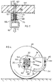
- Figures 4, 5, and 6 illustrate the sequence of steps necessary to accomplish the raising of the wheel 24 of the vehicle 22.
- the elongated body member 28 is shown in the stored position. It must first be released to its initial deployed position (see Figure 5) in contact with the ground.
- a pulling force is applied to the pin member 62 in the direction shown by arrow C in Figure 7, so as to overcome the biasing force and remove the pin member 62 from the latched configuration. This action allows the elongated body member 28 to drop to the initial deployed position as shown in Figure 5.
- the coil compression spring 68 will urge the pin member 62 back toward the latched configuration, but when the elongated body member 28 has been rotated to the initial deployed position, the edge slot 60 will no longer be in register with the pin member passages 64, 66. Consequently, the pin member 62 will slidably abut the elongated body member 28, but will be unable to slide into the latched configuration.
- the van operator then reverses the van 21 to begin movement of the vehicle 22 in a direction toward the second lateral edge 42 of the elongated body member 28, (ie. in the direction indicated by arrow D of Figure 5).
- the radiused lifting surface 34 of the elongated body member 28 is in the initial deployed position in contact with the ground with the tread pattern 44 on the radiused lifting surface 34 frictionally engaging the ground.
- the radiused lifting surface 34 will begin to rotate relative to the ground in response to said motion of the vehicle 22 and said frictional engagement, causing the concave arcuate surface 46 of the elongated body member 28 to rotate against the circumferential bearing surface 52 of the annular split section adaptor coupling 48.
- the distance between the foot portion 40 and the top end portion 30 is greatest along the longitudinal axis A of the elongated body member 28, and when the foot portion 40 is in horizontal resting contact upon the ground in the fully deployed position of Figure 6, the axle 26 of the vehicle 22 will rest indirectly upon the elongated body member 28, resulting in an increased height above the ground of approximately 1.5 to 2 inches.
- the adjacent attached wheel 24 is, thus, maintained out of contact with the ground.
- the fully deployed position, wherein the foot portion 40 contacts the ground is a position of stability for the elongated body member 28, since in this position the longitudinal axis A of the elongated body member 28 is substantially aligned with the true vertical direction.
- the elongated body member 28 As the elongated body member 28 achieves the fully deployed position, it tends to do so somewhat abruptly, as the bottom end portion 32 is contoured such that the foot portion 40 extends in a radially inwardly tangential relation to the curvature of the radiused lifting surface 34.
- a "thumping" sensation noticeable to the operator of the van 21 occurs upon contact of the foot portion 40 with the ground. This is especially noticeable if both lift jacks 20, as seen in Figure 1, are simultaneously deployed. The operator can rely upon the occurrence of this thumping as an indication that the vehicle has reached a stable elevated position upon the lift jack 20. Moreover, the stability of this position will resist further motion in the direction of arrow D, in certain instances almost to the point of stalling the engine of the van 21.
- the lift jack 20 of the present invention can be operated by a single individual without the need for someone to signal to the operator when lifting has been completed; however, such an additional “spotter” is advisable for safety reasons.
- the operator In order to release the lift jack 20 and lower the vehicle 22 from the said position shown in Figure 6, the operator would simply pull the vehicle 22 forward (ie. in a direction opposite to that of arrow D of Figure 5), causing the radiused lifting surface 34 of the elongated body member 28 to rotate in the opposite direction. The engagement of the foot portion 40 with the ground is thus gradually released, and as the elongated body portion 28 completes its forward rotational movement along the path dictated by the radiused lifting surface 34, the vehicle is lowered. Once the vehicle 22 has been safely lowered, and the elongated body member 28 has returned to its initial deployed position (shown in Figure 5), the elongated body member may then be manually returned to its stored position (shown in Figure 4).
- the elongated body member 28 is rotated manually to the stored position by the operator.
- the edge slot 60 is again in register with the first 64 and second 66 pin member guide holes.
- the elongated body member 28 is preferably provided with a groove 74 adjacent the second lateral edge 42, which groove 74 is adapted to accommodate the passage of vehicle brake cables (not shown), such that the elongated body member 28 will not press upon the brake cables of the vehicle 22 when the elongated body member 28 is secured in its stored position.
- each connecting bracket 54 can, as illustrated in the appended Figures, be constructed as two substantially identical half-brackets 54a and 54b, which half-brackets are positioned at opposed sides of said axle 26, and then attached together, such that the axle 26 is retained within the central opening 56 defined by each connecting bracket 54.
- the connecting brackets 54 are preferably manufactured to a standard size, with the central opening 56 of a uniform size and shape sufficiently large to accommodate passage therethrough of a wide variety of vehicle axles 26.
- annular split section adaptor couplings 48 having central openings in a range of standard sizes and shapes could economically be manufactured from which to select a particular annular split section adaptor coupling 48 having the necessary specifications to fit around the axle 26 of a given make and model of vehicle 22. Accordingly, the lift jack 20 of the present invention may be efficiently manufactured for sale as an after-market add-on product which is readily adaptable for permanent mounting to a wide range of vehicles, including recreational vehicles, automobiles, and light trucks.
- the order of assembly on the vehicle 22 of the component parts of the lift jack 20 for installation in an after-market context would be as follows.
- the two mirror-image sections 48a and 48b of the annular split adaptor coupling 48 would be positioned around the axle 26 and manually held in place in encircling fixed relation.
- the elongated body member 28 would then be positioned with the concave arcuate surface 46 of the top end portion 30 encircling the axle 26.
- the elongated body member is then moved laterally toward the annular split adaptor coupling 48 so as to bring the concave arcuate surface 46 of top portion 30 into aligned, slip-fitting frictional contact with the circumferential bearing surface 52 of the annular split adaptor coupling 48, thus securing the sections 48a and 48b together, and simultaneously indirectly mounting elongated body portion 28 on the axle 26.
- the half-brackets 54a and 54b of each connecting bracket 54 are then positioned to define a central opening 56 therethrough coaxial with the axle 26, with one connecting bracket 54 on each axial side of the annular split section adaptor coupling 48 as shown in the Figures.
- the connecting brackets 54, 54 are then rigidly attached one to the other by the throughpassage of the screw threaded bolts 59 through the secondary openings 58 in each connecting bracket and the secondary openings 51 in the coupling 48.
- Correspondingly threaded nuts 61 are then attached and tightened on each of the bolts 59 to secure the assembly.
- the lift jack 20 of the present invention is optimally designed as an after-market add on for use with most vehicles.
- the invention could be installed as original equipment on recreational or other vehicles wherein the annular split section adaptor coupling 48 would advantageously be fabricated as a single component welded directly to the axle 26.
- each of the connecting brackets 54 could be manufactured to dimensions customized for installation on a particular vehicle.
- the connecting brackets could each be manufactured as a unitary structure, rather than in the form of two half-brackets as shown in the Figures.
- Connecting brackets having such a unitary structure would have to be installed on the axle sequentially, before mounting of the brake backing plates etc., with one connecting bracket fitted to the axle, then the annular split section adaptor coupling mounted and welded to the axle, then the elongated body member slid over the split section adaptor coupling, and finally the remaining connecting bracket would be installed and the assembly bolted together as aforesaid.
- the lift jack of the present invention has been illustrated and described with reference to use on a recreational trailer, it can easily and routinely be adapted for use on other vehicles, including passenger automobiles, with similar utility.
- the "structural member" in such applications need not be a wheel axle of the vehicle, but may be provided on the underside of the vehicle for the specific purpose of mounting one or more lift jacks according to the present invention thereon. This is thought particularly appropriate where the lift jacks are to be mounted on a passenger vehicle adjacent front wheels of the vehicle.
- the central opening through the half-brackets may be reduced to be slightly smaller than the outside dimension of the axle, so that additional clamping force will be asserted by the half-brackets on the axle.
- cross-bolts (not shown) can be used to transversely connect the flanges of respective half-brackets to each other, one above, and one below (and both transverse to) the axle.
Landscapes
- Engineering & Computer Science (AREA)
- Mechanical Engineering (AREA)
- Vehicle Cleaning, Maintenance, Repair, Refitting, And Outriggers (AREA)
Claims (11)
- Cric (20) destiné à être utilisé avec un véhicule (22) ayant une structure (26) placée sur le dessous du véhicule afin de définir un axe transversal de rotation (B), ledit cric (20) comportant un corps allongé (28) ayant un axe longitudinal (A), une extrémité supérieure (30) adjacente à une première extrémité dudit axe longitudinal (A), ladite extrémité supérieure ayant une surface arquée concave (46) alignée de manière radiale avec ledit axe longitudinal (A), l'arc de ladite surface arquée concave (46) définissant un axe central co-alignable avec ledit axe de rotation (B), et une extrémité inférieure (32) adjacente à l'autre extrémité, opposée, dudit axe longitudinal (A), ladite extrémité inférieure ayant une surface de levage rayonnée (34) et un pied globalement plat (40) croisant ledit axe longitudinal (A) en étant orienté d'une manière sensiblement transversale à celui-ci et s'étendant de manière contiguë depuis ladite surface de levage rayonnée (34), et d'une manière tangentielle, sensiblement radialement vers l'intérieur, par rapport à ladite surface de levage rayonnée (34) vers un second bord latéral (42) de ladite extrémité inférieure (32) décalé latéralement vers l'autre côté latéral opposé dudit axe longitudinal (A), la longueur axiale longitudinale dudit corps allongé (28) étant supérieure à la hauteur dudit axe transversal de rotation (B) au-dessus du sol, une surface porteuse circonférentielle (52) étant dimensionnée pour se loger dans ladite surface arquée concave de ladite extrémité supérieure, en contact à frottement à ajustement serré avec celle-ci pour faciliter le mouvement de rotation séquentiel dudit corps allongé (28) autour dudit axe transversal de rotation (B) depuis une position de rangement dans laquelle l'extrémité inférieure (32) est soulevée à distance du sol, via une position de début de déploiement dans laquelle la surface de levage rayonnée (34) est au contact du sol, jusqu'à une position de déploiement complet dans laquelle ledit pied (40) est au contact du sol et l'axe longitudinal (A) du corps allongé (28) est sensiblement aligné avec la direction verticale vraie, afin de soulever le véhicule (22) au-dessus du sol, ledit cric étant caractérisé en ce que:la surface de levage rayonnée (34) s'étend le long d'un premier bord latéral (36) de ladite extrémité inférieure (32) décalée latéralement vers un côté dudit axe longitudinal (A), l'origine (38) du rayon de ladite surface de levage rayonnée se trouvant sur ledit axe longitudinal (A), et en ce quedes moyens (48, 54) sont fixés à ladite extrémité supérieure (30) pour monter le corps allongé (28) sur le véhicule, lesdits moyens (48, 54) comprenant un adaptateur d'accouplement (48) à section annulaire en deux parties installé autour de ladite structure (26) qu'il entoure de manière fixe, ledit adaptateur d'accouplement (48) à section annulaire en deux parties ayant un pourtour extérieur qui définit ladite surface porteuse circonférentielle (52) centrée sur ledit axe transversal de rotation (B) et une ouverture centrale (50) co-alignable avec ledit axe transversal de rotation (B) et dimensionnée pour recevoir ladite structure (26) passant de manière serrée à travers celle-ci.
- Cric (20) selon la revendication 1, comprenant en outre deux ferrures d'accouplement sensiblement planes (54) ayant chacune une ouverture centrale (56), coaxiales audit axe transversal de rotation (B) et dimensionnées pour recevoir la structure (26) passant à travers celles-ci, lesdites ferrures d'accouplement (54) étant reliées d'une manière rigide l'une à l'autre, chacune sur un des côtés axiaux opposés dudit adaptateur d'accouplement (48) à section annulaire en deux parties.
- Cric (20) selon la revendication 2, dans lequelchacune desdites ferrures d'accouplement (54) est traversée par plusieurs ouvertures secondaires (58), chacune desdites plusieurs ouvertures secondaires (51) étant centrée sur un desdits axes transversaux respectifs parallèles audit axe transversal de rotation (B);ledit adaptateur d'accouplement (48) à section annulaire en deux parties étant traversé par plusieurs ouvertures secondaires (51) en nombre égal, chacune desdites plusieurs ouvertures secondaires (51) étant centrée sur un desdits axes transversaux respectifs parallèles audit axe transversal de rotation (B); etdans lequel lesdites plusieurs ouvertures secondaires (58) de chacune desdites ferrures d'accouplement (54) et lesdites plusieurs ouvertures secondaires (51), en nombre égal, dudit adaptateur d'accouplement (48) à section annulaire en deux parties coïncident les unes avec les autres pour que puissent passer à travers celles-ci plusieurs, en nombre égal, pièces de fixation filetées (59, 61) engagées de manière fixe par rapport auxdites ferrures d'accouplement (54) et avec ledit adaptateur d'accouplement (48) à section annulaire en deux parties.
- Cric (20) selon l'une quelconque des revendications 1 à 3, comprenant en outre un moyen de blocage (60, 62, 64, 66, 68) servant à retenir de manière sélective ledit corps allongé (28) dans une position de rangement dans laquelle ladite surface de levage rayonnée (34) et ledit pied (40) sont maintenus soulevés sans contact avec le sol.
- Cric (20) selon la revendication 4, dans lequel ledit moyen de blocage (60, 62, 64, 66, 68) comporte une broche (62) montée de manière sélective dans une position d'accouplement transversal coulissant entre lesdites ferrures d'accouplement (54) afin d'engager sélectivement ledit corps allongé dans ladite position de rangement afin d'empêcher ledit corps allongé (28) de tourner de ladite position de rangement à ladite position de début de déploiement, et comprenant en outre un moyen de poussée (68) reliant l'une desdites ferrures d'accouplement (54) à ladite broche (62) afin de pousser la broche (62) vers ladite position d'accouplement transversal coulissant.
- Cric (20) selon la revendication 5, dans lequel ladite broche (62) est traversée par une fente transversale (72), et ledit moyen de poussée (68) comporte un ressort hélicoïdal de compression ayant un corps (71) entourant la broche (62) et ayant des faces d'extrémités libres opposées retenues de manière utile entre l'une, choisie, desdites ferrures d'accouplement (54) et un rebord respectif (55) de celle-ci, orienté axialement vers l'extérieur, l'une des deux pointes d'extrémités dudit ressort hélicoïdal de compression (68) passant à travers ladite fente transversale (72), afin de pousser ladite broche (62) comme indiqué plus haut vers la configuration verrouillée.
- Cric (20) selon l'une quelconque des revendications 1 à 6, dans lequel ladite surface de levage rayonnée (34) et ledit pied sont profilés pour être en contact à frottement avec le sol, comportant un motif de sculptures continu (44) s'étendant sur la surface de levage rayonnée (34) et le pied (40).
- Cric (20) selon l'une quelconque des revendications 1 à 7, dans lequel ledit corps allongé (28) est en matière légère à grande résistance à la compression, en particulier en matière plastique constituée par du polyéthylène basse densité.
- Cric (20) selon l'une quelconque des revendications 1 à 8, dans lequel ledit corps allongé (28) est sensiblement creux et/ou fabriqué par moulage par rotation.
- Cric (20) selon l'une quelconque des revendications 1 à 9, dans lequel ladite extrémité inférieure (32) du corps allongé (28) a une section transversale plus large que celle de l'extrémité supérieure (30) du corps allongé.
- Cric (20) selon l'une quelconque des revendications 1 à 10, dans lequel ledit corps allongé (28) comporte une gorge (74) au voisinage immédiat dudit autre côté latéral opposé dudit axe longitudinal (A) pour faciliter le passage, à travers celui-ci, d'un câble de frein du véhicule (22) à roues alors que le corps allongé (28) est en position de rangement.
Applications Claiming Priority (3)
| Application Number | Priority Date | Filing Date | Title |
|---|---|---|---|
| US611572 | 1996-03-06 | ||
| US08/611,572 US5702089A (en) | 1996-03-06 | 1996-03-06 | Lift jack for wheeled vehicle |
| PCT/CA1997/000110 WO1997032763A1 (fr) | 1996-03-06 | 1997-02-18 | Cric pour vehicule a roues |
Publications (2)
| Publication Number | Publication Date |
|---|---|
| EP0883534A1 EP0883534A1 (fr) | 1998-12-16 |
| EP0883534B1 true EP0883534B1 (fr) | 1999-12-22 |
Family
ID=24449556
Family Applications (1)
| Application Number | Title | Priority Date | Filing Date |
|---|---|---|---|
| EP97904318A Expired - Lifetime EP0883534B1 (fr) | 1996-03-06 | 1997-02-18 | Cric pour vehicule a roues |
Country Status (6)
| Country | Link |
|---|---|
| US (1) | US5702089A (fr) |
| EP (1) | EP0883534B1 (fr) |
| AU (1) | AU1714897A (fr) |
| CA (1) | CA2247999A1 (fr) |
| DE (1) | DE69700988T2 (fr) |
| WO (1) | WO1997032763A1 (fr) |
Families Citing this family (6)
| Publication number | Priority date | Publication date | Assignee | Title |
|---|---|---|---|---|
| IT249214Y1 (it) * | 2000-06-22 | 2003-04-03 | Fabio Riccardi | Dispositivo per il sollevamento delle ruote di un veicolo. |
| US6701699B2 (en) | 2001-04-25 | 2004-03-09 | The Toro Company | On-board vehicle jacking apparatus and methods of using same |
| US8702062B2 (en) * | 2009-11-13 | 2014-04-22 | Exmark Manufacturing Company, Incorporated | Jack mount/system and vehicle incorporating same |
| US9586796B1 (en) * | 2014-02-26 | 2017-03-07 | Gordon Earl Brand | Axle lifting implement |
| CN103847710B (zh) * | 2014-03-24 | 2016-04-13 | 大连理工大学 | 车用越障助力装置 |
| US11155197B2 (en) | 2018-06-25 | 2021-10-26 | James Norman Kirk | Lift stand for vehicles and trailers |
Family Cites Families (10)
| Publication number | Priority date | Publication date | Assignee | Title |
|---|---|---|---|---|
| US1682856A (en) * | 1927-05-18 | 1928-09-04 | Samuel M Salkind | Vehicle jack |
| US2143181A (en) * | 1933-04-06 | 1939-01-10 | Barr John Lester | Parking device |
| FR758568A (fr) * | 1933-07-18 | 1934-01-19 | Appareil pour soulever les véhicules | |
| GB430181A (en) * | 1934-01-10 | 1935-06-14 | James Allen | Improvements in or relating to means for lifting wheels of motor vehicles |
| DE684626C (de) * | 1938-01-04 | 1939-12-01 | Georges Bourguet | Hebevorrichtung fuer Kraftfahrzeuge |
| US2201373A (en) * | 1938-09-28 | 1940-05-21 | Miniconi Henri Jules | Automatic jack device for automobiles |
| US3733051A (en) * | 1971-04-30 | 1973-05-15 | R Bollinger | Trailer jack |
| US3881746A (en) * | 1972-12-19 | 1975-05-06 | Jr C Lewis Newcomb | Vehicle leveler system |
| FR2534238A1 (fr) * | 1982-10-12 | 1984-04-13 | Renault | Cric a losange articule |
| US5215289A (en) * | 1992-04-29 | 1993-06-01 | Jacobson Jan E F | Trailer lifting device |
-
1996
- 1996-03-06 US US08/611,572 patent/US5702089A/en not_active Expired - Fee Related
-
1997
- 1997-02-18 CA CA002247999A patent/CA2247999A1/fr not_active Abandoned
- 1997-02-18 EP EP97904318A patent/EP0883534B1/fr not_active Expired - Lifetime
- 1997-02-18 DE DE69700988T patent/DE69700988T2/de not_active Expired - Fee Related
- 1997-02-18 WO PCT/CA1997/000110 patent/WO1997032763A1/fr not_active Ceased
- 1997-02-18 AU AU17148/97A patent/AU1714897A/en not_active Abandoned
Also Published As
| Publication number | Publication date |
|---|---|
| AU1714897A (en) | 1997-09-22 |
| DE69700988D1 (de) | 2000-01-27 |
| DE69700988T2 (de) | 2001-01-18 |
| CA2247999A1 (fr) | 1997-09-12 |
| WO1997032763A1 (fr) | 1997-09-12 |
| EP0883534A1 (fr) | 1998-12-16 |
| US5702089A (en) | 1997-12-30 |
Similar Documents
| Publication | Publication Date | Title |
|---|---|---|
| US6213491B1 (en) | Vehicle trailer having spare time adapter apparatus | |
| US4514002A (en) | Two-position bumper | |
| US6378956B1 (en) | Wheel chock assembly | |
| US8840000B1 (en) | Heavy duty leveraged spare tire carrier | |
| US5540540A (en) | Towing device with wheel restraint | |
| US4666216A (en) | Emergency wheel mountable on vehicle wheel and method of use | |
| US8720760B1 (en) | Heavy duty, leveraged spare tire carrier | |
| EP0883534B1 (fr) | Cric pour vehicule a roues | |
| US5513684A (en) | Anti-skid device for automobile tires | |
| US5813687A (en) | Spare wheel assembly for trailers | |
| US5672042A (en) | Underlift assembly tow trucks | |
| US5191934A (en) | Portable tire bead breaker apparatus | |
| WO1993018936A1 (fr) | Dispositif de remorque de motocycles | |
| US5350029A (en) | Automobile emergency accessory | |
| US20040161323A1 (en) | Vehicular towing apparatus using air lift | |
| US4890852A (en) | Tow mechanism for vehicles | |
| US5860670A (en) | Trailer towing device | |
| US4993910A (en) | Adjustable device for towing vehicles with vertical lift | |
| US7108336B2 (en) | Emergency axle | |
| US5215289A (en) | Trailer lifting device | |
| US6279950B1 (en) | Axle crutch | |
| US5961137A (en) | Wheel restraint safety system | |
| US6164679A (en) | Spare wheel assembly for trailers | |
| GB2290590A (en) | Restraining device for a vehicle wheel | |
| US5016933A (en) | Automotive bumper and tailgate |
Legal Events
| Date | Code | Title | Description |
|---|---|---|---|
| PUAI | Public reference made under article 153(3) epc to a published international application that has entered the european phase |
Free format text: ORIGINAL CODE: 0009012 |
|
| 17P | Request for examination filed |
Effective date: 19980904 |
|
| AK | Designated contracting states |
Kind code of ref document: A1 Designated state(s): DE ES FR GB SE |
|
| GRAG | Despatch of communication of intention to grant |
Free format text: ORIGINAL CODE: EPIDOS AGRA |
|
| 17Q | First examination report despatched |
Effective date: 19990128 |
|
| GRAG | Despatch of communication of intention to grant |
Free format text: ORIGINAL CODE: EPIDOS AGRA |
|
| GRAH | Despatch of communication of intention to grant a patent |
Free format text: ORIGINAL CODE: EPIDOS IGRA |
|
| GRAH | Despatch of communication of intention to grant a patent |
Free format text: ORIGINAL CODE: EPIDOS IGRA |
|
| GRAA | (expected) grant |
Free format text: ORIGINAL CODE: 0009210 |
|
| AK | Designated contracting states |
Kind code of ref document: B1 Designated state(s): DE ES FR GB SE |
|
| PG25 | Lapsed in a contracting state [announced via postgrant information from national office to epo] |
Ref country code: SE Free format text: THE PATENT HAS BEEN ANNULLED BY A DECISION OF A NATIONAL AUTHORITY Effective date: 19991222 Ref country code: FR Free format text: LAPSE BECAUSE OF FAILURE TO SUBMIT A TRANSLATION OF THE DESCRIPTION OR TO PAY THE FEE WITHIN THE PRESCRIBED TIME-LIMIT Effective date: 19991222 Ref country code: ES Free format text: THE PATENT HAS BEEN ANNULLED BY A DECISION OF A NATIONAL AUTHORITY Effective date: 19991222 |
|
| REF | Corresponds to: |
Ref document number: 69700988 Country of ref document: DE Date of ref document: 20000127 |
|
| EN | Fr: translation not filed | ||
| REG | Reference to a national code |
Ref country code: GB Ref legal event code: 732E |
|
| PLBE | No opposition filed within time limit |
Free format text: ORIGINAL CODE: 0009261 |
|
| STAA | Information on the status of an ep patent application or granted ep patent |
Free format text: STATUS: NO OPPOSITION FILED WITHIN TIME LIMIT |
|
| 26N | No opposition filed | ||
| PGFP | Annual fee paid to national office [announced via postgrant information from national office to epo] |
Ref country code: GB Payment date: 20010301 Year of fee payment: 5 |
|
| PGFP | Annual fee paid to national office [announced via postgrant information from national office to epo] |
Ref country code: DE Payment date: 20010426 Year of fee payment: 5 |
|
| REG | Reference to a national code |
Ref country code: GB Ref legal event code: IF02 |
|
| PG25 | Lapsed in a contracting state [announced via postgrant information from national office to epo] |
Ref country code: GB Free format text: LAPSE BECAUSE OF NON-PAYMENT OF DUE FEES Effective date: 20020218 |
|
| PG25 | Lapsed in a contracting state [announced via postgrant information from national office to epo] |
Ref country code: DE Free format text: LAPSE BECAUSE OF NON-PAYMENT OF DUE FEES Effective date: 20020903 |
|
| GBPC | Gb: european patent ceased through non-payment of renewal fee |
Effective date: 20020218 |