EP0883795B1 - Dispositif pour determiner la vitesse de rotation - Google Patents
Dispositif pour determiner la vitesse de rotation Download PDFInfo
- Publication number
- EP0883795B1 EP0883795B1 EP97911129A EP97911129A EP0883795B1 EP 0883795 B1 EP0883795 B1 EP 0883795B1 EP 97911129 A EP97911129 A EP 97911129A EP 97911129 A EP97911129 A EP 97911129A EP 0883795 B1 EP0883795 B1 EP 0883795B1
- Authority
- EP
- European Patent Office
- Prior art keywords
- rotational speed
- voltage
- signal
- vibration
- determining
- Prior art date
- Legal status (The legal status is an assumption and is not a legal conclusion. Google has not performed a legal analysis and makes no representation as to the accuracy of the status listed.)
- Expired - Lifetime
Links
- 230000001133 acceleration Effects 0.000 claims description 41
- 238000011156 evaluation Methods 0.000 claims description 18
- 238000012360 testing method Methods 0.000 claims description 18
- 230000006978 adaptation Effects 0.000 claims description 13
- 238000012546 transfer Methods 0.000 claims description 10
- 238000004088 simulation Methods 0.000 claims description 6
- 230000003044 adaptive effect Effects 0.000 claims description 5
- 238000001914 filtration Methods 0.000 claims description 3
- 230000001143 conditioned effect Effects 0.000 claims 1
- 238000000034 method Methods 0.000 description 10
- 230000010355 oscillation Effects 0.000 description 5
- 230000000694 effects Effects 0.000 description 4
- 238000010586 diagram Methods 0.000 description 3
- 230000010363 phase shift Effects 0.000 description 3
- 238000012545 processing Methods 0.000 description 3
- 230000001105 regulatory effect Effects 0.000 description 3
- 230000009897 systematic effect Effects 0.000 description 3
- 230000005284 excitation Effects 0.000 description 2
- 230000010358 mechanical oscillation Effects 0.000 description 2
- 101150071746 Pbsn gene Proteins 0.000 description 1
- 238000006243 chemical reaction Methods 0.000 description 1
- 238000001514 detection method Methods 0.000 description 1
- 230000000670 limiting effect Effects 0.000 description 1
- 230000005923 long-lasting effect Effects 0.000 description 1
- 230000007257 malfunction Effects 0.000 description 1
- 238000005259 measurement Methods 0.000 description 1
- 238000012552 review Methods 0.000 description 1
Images
Classifications
-
- G—PHYSICS
- G01—MEASURING; TESTING
- G01C—MEASURING DISTANCES, LEVELS OR BEARINGS; SURVEYING; NAVIGATION; GYROSCOPIC INSTRUMENTS; PHOTOGRAMMETRY OR VIDEOGRAMMETRY
- G01C19/00—Gyroscopes; Turn-sensitive devices using vibrating masses; Turn-sensitive devices without moving masses; Measuring angular rate using gyroscopic effects
- G01C19/56—Turn-sensitive devices using vibrating masses, e.g. vibratory angular rate sensors based on Coriolis forces
Definitions
- the invention is based on a device for determining a rotation rate according to the type of the main claim.
- rotation rate sensors which take advantage of the Coriolis effect, is known in connection with systems for driving dynamics control in motor vehicles.
- Such rotation rate sensors usually consist of one or more masses which are excited by a voltage generated in an electrical circuit to mechanical vibrations with the frequency f s .
- These mechanical vibrations act on one or more acceleration sensors which, when the system rotates, also measure the Coriolis acceleration acting on the vibrating masses.
- the rotation rate of the system can be determined from the excitation and acceleration signals with the aid of a suitable evaluation circuit.
- the known device for determining a rotation rate comprises a rotation rate sensor based on the principle of a resonant Vibration gyrometer works and by means of a amplitude-controlled oscillator loop is excited.
- This Sensor is used, for example, the yaw rate to determine a vehicle.
- the Effect of Coriolis acceleration is evaluated, which is a measure for the current yaw rate.
- the functionality of the sensor or the associated one Electronics becomes additional at certain selectable times Voltage, for example as a BITE function, is fed in and the system's response to this additional Voltage evaluated for error detection.
- the device according to the invention with the features of the secondary Claims 1 or 4 have compared to the known Device the advantage that a purely digital signal processing takes place while in the known device working with an analog circuit.
- the stake of adaptive methods of digital signal processing enables advantageous system identification and system simulation. Sensor errors can be eliminated through the adaptation processes compensate successfully.
- the invention digital evaluation circuit is advantageously full integrable and has no problems with synchronism and Drift of the individual components.
- the circuit is up adjustment to a scaling factor.
- FIG. 1 shows a block diagram of a rotation rate sensor
- FIG. 2 shows a first evaluation circuit
- FIG. 3 shows a second evaluation circuit for the Output signals of a rotation rate sensor according to FIG. 1.
- the mechanical oscillator for example a hollow cylinder clamped on one side, bears the reference number 10.
- This oscillator is set into mechanical vibrations by an electrical circuit.
- the electrical circuit comprises the two amplifiers 11 and 12.
- Amplifier 11 is a regulated amplifier or has limiting properties.
- the associated output signal is referred to as oscillating signal U 1 .
- the acceleration sensor 13 or the acceleration sensors are still influenced by the Coriolis acceleration ac.
- a test signal U T can be supplied, which has an additional, arbitrarily generated acceleration acting on the acceleration sensor 13.
- the yaw rate D can be determined from the oscillating voltage U 1 and the output voltage U 2 using the digital evaluation circuits shown in FIGS. 2 and 3.
- the circuit shown in FIG. 2 thus enables the yaw rate D of the system to be determined from excitation and acceleration signals.
- the circuit shown in FIG. 3 additionally uses a test signal U T.
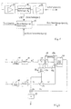
- FIG. 2 shows a first evaluation circuit with which the voltages U 1 and U 2 are evaluated.
- the oscillation voltage U 1 (t) which is proportional to the instantaneous speed v (t) of the mechanical oscillation
- the electrical acceleration signal that is to say the output voltage U 2 (t)
- the output signal U 2 of the acceleration sensor is also already digital, this applies in particular if the acceleration information is already obtained digitally using a so-called sigma-delta method.
- the digitized signals are each filtered with identical bandpasses 16, 17, the center frequency of which is close to the mechanical oscillation frequency f s .
- the transfer function H nb12 (z) simulates all interference components that occur at the rotation rate 0 and have the oscillation frequency f s . If it is assumed that the essential interference component has a phase shift of 90 ° to the speed v and thus to the Coriolis acceleration ac, the evaluation described below can be carried out.
- a branch of a digital 90 ° Hilbert filter 18 is included in the system identification.
- the output voltage of the bandpass 16 is fed to this Hilbert filter 18 via an FIR filter 19.
- the Hilbert filter 18 also has a branch 18a, the voltage of which has a phase shift of 90 ° to the first branch 18b.
- the amplitude of the output signal of the second branch U 90 is regulated in the amplitude control 20.
- This type of control is useful with a constant amplitude of the speed v or with a constant amplitude of the voltage U 1 .
- This type of control is useful for a variable amplitude of the speed v or for a variable amplitude of the voltage U 1 .
- the analog / digitally converted and bandpass-filtered acceleration signal U 2 ' which arises at the output of the bandpass 17, is fed to a summation point 21, as is the signal U 2 "which arises at the output of the Hilbert filter 18.
- the resulting signal e represents the adjusted acceleration signal which is demodulated by multiplication with the normalized signal U 90'.
- the demodulation is designated in Figure 2 as item 22.
- the demodulated signal is in Subsequent low-pass filter is freed from the double oscillation frequency 2f S that arises during multiplication and the noise bandwidth is reduced.
- the signal e is also used as an error signal to control the Adaption used.
- the adaptation process must therefore be very be done slowly, for example in the minute range, otherwise constant angular rates are also compensated for over a longer period of time would.
- the adaptation speed can be advantageous from outside with the help of additional information, for example "Sensor at rest” can be controlled. It can therefore be a fast adaptation at rest and slow adaptation in normal operation realize.
- Figure 2 are the adaptation processes summarized in a block 24, the one input 25 the additional information can be supplied.
- the adaptation level affects the filter stage 19 via corresponding Links.
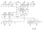
- FIG. 3 shows a further digital evaluation circuit which allows signal evaluation according to a second method.
- the oscillating voltage U 1 and the acceleration voltage U 2 are in turn first supplied to an analog / digital converter 26, 27 and a bandpass filter 28, 29, respectively.
- the voltages U 1 'and U 2 ' then arise at the outputs of the bandpass filters 28, 29.
- test signal U TD is generated which has frequency components in the vicinity of the oscillation frequency of the mechanical oscillator and which, for. B. can be sinusoidal or rectangular. So-called pseudo-binary noise (PRBS, PN sequence) is also suitable as a test signal.
- PRBS pseudo-binary noise
- This test signal is converted in a digital / analog converter 31 and supplied to the acceleration sensor as voltage U T , as shown in FIG. 1.
- the transfer function H NbT2 (z) from the input U T to the output U 2 according to FIG. 1 is identified and simulated.
- the voltage U 2 '' simulates the analog / digitally converted and bandpass-filtered acceleration voltage. It is subtracted from the actual acceleration voltage U 2 'at the summation point 35, which produces the error signal e which controls the adaptation algorithm, which is shown as block 36.
- the signal e no longer contains any test signal components, but all signal components caused by the mechanical rotation rate D to be measured.
- the analog / digitally converted and bandpass-filtered oscillation voltage U 1 ' is filtered with a second FIR filter 37, the coefficients of which are a copy of the coefficients of the filter 34.
- the signal U 1 ′′ obtained in this way is suitable due to its phase position for the demodulation of the rotation rate signal contained in the signal e.
- the voltage U 2 ′′ must be standardized beforehand, as described in the first method. For this purpose, it is fed to an amplitude control 38, at the output of which the voltage U 1 '''is generated, which is multiplied at point 39 by the signal e.
- the rotation rate signal D is obtained after the digital / analog conversion in the D / A converter 41.
Landscapes
- Physics & Mathematics (AREA)
- Engineering & Computer Science (AREA)
- General Physics & Mathematics (AREA)
- Radar, Positioning & Navigation (AREA)
- Remote Sensing (AREA)
- Gyroscopes (AREA)
Claims (13)
- Dispositif pour déterminer une vitesse de rotation à l'aide d'un corps susceptible de vibrer, mis en vibration constante à l'aide d'une tension d'oscillations (U1) générée par un circuit électrique, comportant au moins un élément de capteur installé sur le corps susceptible de vibrer et fournissant une tension de sortie (U2) qui est une mesure de l'accélération et ainsi de la vitesse de rotation,
caractérisé en ce qu'
on détecte et on numérise la tension d'oscillations (U1) proportionnelle à la vitesse instantanée v(t) du corps vibrant,
on numérise la tension de sortie (U2) ou on génère d'emblée un signal numérique, et
à partir des deux tensions (U1, U2) numériques, on forme la fonction de transfert qui copie toutes les composantes perturbatrices pour la vitesse de rotation nulle et constitue le point de départ de la détermination de la vitesse de rotation. - Dispositif pour déterminer une vitesse de rotation selon la revendication 1,
caractérisé en ce qu'
on applique la tension d'oscillations (U1) préparée par l'intermédiaire d'un filtre FIR (19) à un filtre de Hilbert (18) dont une branche fournit une tension de sortie (U2") qui correspond au signal perturbateur copié que l'on retranche en un point de sommation (21) de la tension (U'2) numérisée et filtrée par un filtre passe-bande, pour former un signal d'erreur (e) que l'on multiplie par un signal en régulation d'amplitude obtenu à partir de la seconde branche du filtre de Hilbert et qui après filtrage dans un filtre passe-bas (23) donne la vitesse de rotation. - Dispositif pour déterminer une vitesse de rotation selon la revendication 2,
caractérisé en ce qu'
on règle les coefficients du filtre (19) par un moyen d'adaptation (24) commandé par un signal d'erreur (e), pour adapter les propriétés du filtre (19) aux conditions existantes. - Dispositif pour déterminer une vitesse de rotation à l'aide d'un corps susceptible de vibrer, mis en vibrations constantes par une tension d'oscillations (U1) fournie par un circuit électrique, avec au moins un élément de capteur installé sur le corps susceptible de vibrer et fournissant une tension de sortie (U2) qui est une mesure de l'accélération et ainsi également de la vitesse de rotation,
caractérisé en ce qu'
on détecte et on numérise la tension oscillante (U1) proportionnelle à la vitesse instantanée v(t) du corps susceptible de vibrer,
on numérise la tension de sortie (U2) ou on la fournit déjà comme signal numérique, et
en plus on génère un signal de test (UT) comportant les composantes de fréquence à proximité de la fréquence d'oscillations de l'oscillateur mécanique et on fournit ce signal en plus au capteur d'accélération,
on copie de manière numérique les modifications produites par le signal de test et on retranche ce signal copié de la tension d'accélération effective. - Dispositif pour déterminer une vitesse de rotation selon la revendication 4,
caractérisé en ce qu'
on identifie la fonction de transfert entre le signal de test (UT) et la tension de sortie (U2), et on la copie et on en tient compte pour déterminer la vitesse de rotation. - Dispositif pour déterminer une vitesse de rotation selon la revendication 5,
caractérisé en ce qu'
on applique les tensions numérisées et filtrées par un filtre passe-bande (U1') et (UT') chaque fois à un filtre adaptatif FIR (34, 37), l'adaptation se faisant en fonction de la tension d'accélération numérisée et filtrée par un filtre passe-bande (U2") et en fonction de la tension d'accélération effective (U2'). - Dispositif pour déterminer une vitesse de rotation selon la revendication 6,
caractérisé en ce qu'
on commande les coefficients des filtres identiques FIR (34, 37) par un algorithme d'adaptation (36) commandé par un signal d'erreur (e) en réglant de façon que les filtres FIR copient la fonction de transfert du signal de contrôle (UT) vers la tension de sortie (U2). - Dispositif pour déterminer une vitesse de rotation selon la revendication 7,
caractérisé en ce qu'
on régule en amplitude le signal oscillant (U1") numérisé et filtré, et après multiplication du signal oscillant régulé (U1''') avec le signal d'erreur (e) et filtrage dans un filtre passe-bas (40), on obtient le signal de vitesse de rotation (D). - Dispositif selon l'une quelconque des revendications précédentes,
caractérisé en ce qu'
on régule l'amplitude (20) selon la figure 2 ou (38) selon la figure 3 sur une amplitude constante de la tension constante (U90') à la figure 2, ou de la tension (U1''') à la figure 3. - Dispositif selon l'une quelconque des revendications 1 à 8,
caractérisé en ce qu'
on régule l'amplitude (20) à la figure 2 ou (38) à la figure 3 sur une amplitude proportionnelle à la valeur réciproque de l'amplitude de la tension d'oscillations (U1). - Dispositif selon l'une quelconque des revendications précédentes,
caractérisé par
un filtre passe-bas à la sortie du circuit d'exploitation qui sépare par filtrage les composantes de signal de fréquence élevée en particulier les composantes à fréquence d'oscillations double. - Dispositif selon l'une quelconque des revendications précédentes,
caractérisé en ce qu'
on adapte de l'extérieur la vitesse d'adaptation du filtre FIR. - Dispositif selon l'une quelconque des revendications précédentes,
caractérisé en ce que
le circuit d'exploitation numérique est un circuit totalement intégré.
Applications Claiming Priority (3)
| Application Number | Priority Date | Filing Date | Title |
|---|---|---|---|
| DE19653020A DE19653020A1 (de) | 1996-12-19 | 1996-12-19 | Vorrichtung zur Ermittlung einer Drehrate |
| DE19653020 | 1996-12-19 | ||
| PCT/DE1997/002266 WO1998027403A1 (fr) | 1996-12-19 | 1997-10-02 | Dispositif pour determiner la vitesse de rotation |
Publications (2)
| Publication Number | Publication Date |
|---|---|
| EP0883795A1 EP0883795A1 (fr) | 1998-12-16 |
| EP0883795B1 true EP0883795B1 (fr) | 2003-01-08 |
Family
ID=7815363
Family Applications (1)
| Application Number | Title | Priority Date | Filing Date |
|---|---|---|---|
| EP97911129A Expired - Lifetime EP0883795B1 (fr) | 1996-12-19 | 1997-10-02 | Dispositif pour determiner la vitesse de rotation |
Country Status (5)
| Country | Link |
|---|---|
| US (1) | US6205838B1 (fr) |
| EP (1) | EP0883795B1 (fr) |
| JP (1) | JP4219411B2 (fr) |
| DE (2) | DE19653020A1 (fr) |
| WO (1) | WO1998027403A1 (fr) |
Families Citing this family (22)
| Publication number | Priority date | Publication date | Assignee | Title |
|---|---|---|---|---|
| DE19910415B4 (de) | 1999-03-10 | 2010-12-09 | Robert Bosch Gmbh | Verfahren und Vorrichtung zum Abstimmen eines ersten Oszillators mit einem zweiten Oszillator |
| DE50014184D1 (de) * | 2000-10-12 | 2007-05-03 | Flowtec Ag | Prüfgerät für ein Coriolis-Massedurchflussmessgerät |
| DE10059775C2 (de) | 2000-12-01 | 2003-11-27 | Hahn Schickard Ges | Verfahren und Vorrichtung zur Verarbeitung von analogen Ausgangssignalen von kapazitiven Sensoren |
| JP4686909B2 (ja) * | 2001-06-07 | 2011-05-25 | 株式会社アドヴィックス | センサの異常検出方法 |
| DE10317158B4 (de) * | 2003-04-14 | 2007-05-10 | Litef Gmbh | Verfahren zur Ermittlung eines Nullpunktfehlers in einem Corioliskreisel |
| DE10317159B4 (de) * | 2003-04-14 | 2007-10-11 | Litef Gmbh | Verfahren zur Kompensation eines Nullpunktfehlers in einem Corioliskreisel |
| DE10321962B4 (de) * | 2003-05-15 | 2005-08-18 | Hahn-Schickard-Gesellschaft für angewandte Forschung e.V. | Verfahren und Vorrichtung zum Simulieren einer Drehrate und Verwendung von simulierten Drehraten zur initialen Kalibrierung von Drehratensensoren oder zur In-Betrieb-Nachkalibrierung von Drehratensensoren |
| US6934665B2 (en) * | 2003-10-22 | 2005-08-23 | Motorola, Inc. | Electronic sensor with signal conditioning |
| US20050268716A1 (en) * | 2004-06-08 | 2005-12-08 | Honeywell International Inc. | Built in test for mems vibratory type inertial sensors |
| DE102004058183A1 (de) * | 2004-12-02 | 2006-06-08 | Robert Bosch Gmbh | Messfühler mit Selbsttest |
| DE102004061804B4 (de) * | 2004-12-22 | 2015-05-21 | Robert Bosch Gmbh | Mikromechanischer Drehratensensor mit Fehlerunterdrückung |
| DE102005004775A1 (de) * | 2005-02-01 | 2006-08-10 | Robert Bosch Gmbh | Sensor mit Selbsttest |
| FR2914126B1 (fr) * | 2007-03-22 | 2009-05-22 | Eddysense Sarl | Procede de demodulation synchrone et support d'enregistrement pour ce procede, demodulateur synchrone et capteur incorporant ce demodulateur |
| DE102007057136A1 (de) * | 2007-11-28 | 2009-06-04 | Robert Bosch Gmbh | Schaltung für einen mikromechanischen Körperschallsensor und Verfahren zum Betrieb eines mikromechanischen Körperschallsensors |
| DE102009000743B4 (de) | 2009-02-10 | 2024-01-18 | Robert Bosch Gmbh | Vibrationskompensation für Drehratensensoren |
| US8783103B2 (en) * | 2009-08-21 | 2014-07-22 | Analog Devices, Inc. | Offset detection and compensation for micromachined inertial sensors |
| US9212908B2 (en) | 2012-04-26 | 2015-12-15 | Analog Devices, Inc. | MEMS gyroscopes with reduced errors |
| US9109901B2 (en) * | 2013-03-08 | 2015-08-18 | Freescale Semiconductor Inc. | System and method for monitoring a gyroscope |
| US9869552B2 (en) * | 2015-03-20 | 2018-01-16 | Analog Devices, Inc. | Gyroscope that compensates for fluctuations in sensitivity |
| DE102015211258A1 (de) * | 2015-06-18 | 2016-12-22 | Robert Bosch Gmbh | Vorrichtungen und Verfahren zur Auswertung eines Signals von einem Drehwinkelgeber |
| CN113359892B (zh) * | 2021-06-21 | 2022-06-21 | 歌尔股份有限公司 | 振动电机的传递函数生成方法、装置及存储介质 |
| CN117387589A (zh) * | 2023-12-11 | 2024-01-12 | 四川图林科技有限责任公司 | 一种半球谐振陀螺的谐振子检测电极输出信号滤波方法 |
Family Cites Families (3)
| Publication number | Priority date | Publication date | Assignee | Title |
|---|---|---|---|---|
| US4522062A (en) * | 1983-09-02 | 1985-06-11 | Sundstrand Data Control, Inc. | Digital processor for use with an accelerometer based angular rate sensor |
| US5426970A (en) * | 1993-08-02 | 1995-06-27 | New Sd, Inc. | Rotation rate sensor with built in test circuit |
| DE4447005A1 (de) * | 1994-12-29 | 1996-07-04 | Bosch Gmbh Robert | Vorrichtung zur Ermittlung einer Drehrate |
-
1996
- 1996-12-19 DE DE19653020A patent/DE19653020A1/de not_active Withdrawn
-
1997
- 1997-10-02 DE DE59709102T patent/DE59709102D1/de not_active Expired - Lifetime
- 1997-10-02 EP EP97911129A patent/EP0883795B1/fr not_active Expired - Lifetime
- 1997-10-02 WO PCT/DE1997/002266 patent/WO1998027403A1/fr not_active Ceased
- 1997-10-02 US US09/091,913 patent/US6205838B1/en not_active Expired - Lifetime
- 1997-10-02 JP JP52715798A patent/JP4219411B2/ja not_active Expired - Fee Related
Also Published As
| Publication number | Publication date |
|---|---|
| DE59709102D1 (de) | 2003-02-13 |
| WO1998027403A1 (fr) | 1998-06-25 |
| EP0883795A1 (fr) | 1998-12-16 |
| US6205838B1 (en) | 2001-03-27 |
| DE19653020A1 (de) | 1998-06-25 |
| JP2000505904A (ja) | 2000-05-16 |
| JP4219411B2 (ja) | 2009-02-04 |
Similar Documents
| Publication | Publication Date | Title |
|---|---|---|
| EP0883795B1 (fr) | Dispositif pour determiner la vitesse de rotation | |
| DE19910415B4 (de) | Verfahren und Vorrichtung zum Abstimmen eines ersten Oszillators mit einem zweiten Oszillator | |
| DE3431621C2 (de) | Winkelgeschwindigkeitsfühler | |
| DE10239283B4 (de) | Synchrones Detektionsverfahren und Vorrichtung dafür, und Sensorsignaldetektor | |
| EP1123484B1 (fr) | Dispositif pour générer un signal de vitesse de rotation | |
| DE19845185B4 (de) | Sensor mit Resonanzstruktur sowie Vorrichtung und Verfahren zum Selbsttest eines derartigen Sensors | |
| DE3431593C2 (de) | Signalverarbeitungsvorrichtung für einen auf einem Beschleunigungsmesser beruhenden Winkelgeschwindigkeitsfühler | |
| DE10362031B4 (de) | Betriebsverfahren für einen Corioliskreisel und dafür geeignete Auswerte-/Regelelektronik | |
| DE10317159B4 (de) | Verfahren zur Kompensation eines Nullpunktfehlers in einem Corioliskreisel | |
| WO1996021138A1 (fr) | Appareil de determination d'un taux de virage | |
| EP1639318B1 (fr) | Procede de surveillance d'un capteur de vitesse de rotation | |
| EP1613926B1 (fr) | Procede pour determiner une deviation residuelle dans un gyroscope vibrant et gyroscope vibrant avec une determination de deviation residuelle | |
| EP3653991B1 (fr) | Procédé et dispositif de traitement de signal d'adaptation automatique de la fréquence d'un filtre dans une boucle de régulation fermée | |
| DE10053534B4 (de) | Selbstdiagnoseschaltung für Schwinggyroskope | |
| EP1639315B1 (fr) | Procede de surveillance d'un capteur de vitesse de rotation | |
| DE10321962B4 (de) | Verfahren und Vorrichtung zum Simulieren einer Drehrate und Verwendung von simulierten Drehraten zur initialen Kalibrierung von Drehratensensoren oder zur In-Betrieb-Nachkalibrierung von Drehratensensoren | |
| DE69625959T2 (de) | Vorrichtung und Verfahren zum Messen der Winkelgeschwindigkeit | |
| DE10240087C5 (de) | Vibrationskreisel | |
| EP0927351B1 (fr) | Dispositif pour mesurer la qualite de l'air | |
| EP2435787B1 (fr) | Capteur et procédé pour faire fonctionner un capteur | |
| DE102020211467A1 (de) | Schaltung für ein MEMS-Gyroskop sowie ein Verfahren zum Betreiben einer entsprechenden Schaltung | |
| EP1886099B1 (fr) | Debitmetre massique de coriolis et procede pour compenser des erreurs de transmission de son circuit d'entree | |
| EP1554544A1 (fr) | Procede de syntonisation electronique de la frequence d'oscillation de sortie d'un gyroscope vibrant | |
| DE102015003196A1 (de) | Vorrichtung und Verfahren zur Restwertverarbeitung bei der Ansteuerung eines Sensors | |
| EP0999449A1 (fr) | Procédé de détermination d'un erreur de déviation de zéro dans un accéléromètre |
Legal Events
| Date | Code | Title | Description |
|---|---|---|---|
| PUAI | Public reference made under article 153(3) epc to a published international application that has entered the european phase |
Free format text: ORIGINAL CODE: 0009012 |
|
| AK | Designated contracting states |
Kind code of ref document: A1 Designated state(s): DE FR GB |
|
| 17P | Request for examination filed |
Effective date: 19981228 |
|
| GRAG | Despatch of communication of intention to grant |
Free format text: ORIGINAL CODE: EPIDOS AGRA |
|
| 17Q | First examination report despatched |
Effective date: 20020308 |
|
| GRAG | Despatch of communication of intention to grant |
Free format text: ORIGINAL CODE: EPIDOS AGRA |
|
| GRAH | Despatch of communication of intention to grant a patent |
Free format text: ORIGINAL CODE: EPIDOS IGRA |
|
| GRAH | Despatch of communication of intention to grant a patent |
Free format text: ORIGINAL CODE: EPIDOS IGRA |
|
| GRAA | (expected) grant |
Free format text: ORIGINAL CODE: 0009210 |
|
| AK | Designated contracting states |
Kind code of ref document: B1 Designated state(s): DE FR GB |
|
| REG | Reference to a national code |
Ref country code: GB Ref legal event code: FG4D Free format text: NOT ENGLISH |
|
| REF | Corresponds to: |
Ref document number: 59709102 Country of ref document: DE Date of ref document: 20030213 Kind code of ref document: P |
|
| GBT | Gb: translation of ep patent filed (gb section 77(6)(a)/1977) |
Effective date: 20030401 |
|
| ET | Fr: translation filed | ||
| PLBE | No opposition filed within time limit |
Free format text: ORIGINAL CODE: 0009261 |
|
| STAA | Information on the status of an ep patent application or granted ep patent |
Free format text: STATUS: NO OPPOSITION FILED WITHIN TIME LIMIT |
|
| 26N | No opposition filed |
Effective date: 20031009 |
|
| PGFP | Annual fee paid to national office [announced via postgrant information from national office to epo] |
Ref country code: FR Payment date: 20121113 Year of fee payment: 16 |
|
| PGFP | Annual fee paid to national office [announced via postgrant information from national office to epo] |
Ref country code: GB Payment date: 20121023 Year of fee payment: 16 |
|
| PGFP | Annual fee paid to national office [announced via postgrant information from national office to epo] |
Ref country code: DE Payment date: 20121217 Year of fee payment: 16 |
|
| GBPC | Gb: european patent ceased through non-payment of renewal fee |
Effective date: 20131002 |
|
| PG25 | Lapsed in a contracting state [announced via postgrant information from national office to epo] |
Ref country code: GB Free format text: LAPSE BECAUSE OF NON-PAYMENT OF DUE FEES Effective date: 20131002 |
|
| REG | Reference to a national code |
Ref country code: FR Ref legal event code: ST Effective date: 20140630 |
|
| REG | Reference to a national code |
Ref country code: DE Ref legal event code: R119 Ref document number: 59709102 Country of ref document: DE Effective date: 20140501 |
|
| PG25 | Lapsed in a contracting state [announced via postgrant information from national office to epo] |
Ref country code: DE Free format text: LAPSE BECAUSE OF NON-PAYMENT OF DUE FEES Effective date: 20140501 Ref country code: FR Free format text: LAPSE BECAUSE OF NON-PAYMENT OF DUE FEES Effective date: 20131031 |