EP0884137A2 - Kupplungsstück für lösbare Verbindung an Werkzeugen - Google Patents
Kupplungsstück für lösbare Verbindung an Werkzeugen Download PDFInfo
- Publication number
- EP0884137A2 EP0884137A2 EP98109971A EP98109971A EP0884137A2 EP 0884137 A2 EP0884137 A2 EP 0884137A2 EP 98109971 A EP98109971 A EP 98109971A EP 98109971 A EP98109971 A EP 98109971A EP 0884137 A2 EP0884137 A2 EP 0884137A2
- Authority
- EP
- European Patent Office
- Prior art keywords
- seat
- square
- mandrel
- locking pin
- cone
- Prior art date
- Legal status (The legal status is an assumption and is not a legal conclusion. Google has not performed a legal analysis and makes no representation as to the accuracy of the status listed.)
- Granted
Links
Images


Classifications
-
- B—PERFORMING OPERATIONS; TRANSPORTING
- B25—HAND TOOLS; PORTABLE POWER-DRIVEN TOOLS; MANIPULATORS
- B25B—TOOLS OR BENCH DEVICES NOT OTHERWISE PROVIDED FOR, FOR FASTENING, CONNECTING, DISENGAGING, OR HOLDING
- B25B13/00—Spanners; Wrenches
- B25B13/46—Spanners; Wrenches of the ratchet type, for providing a free return stroke of the handle
- B25B13/461—Spanners; Wrenches of the ratchet type, for providing a free return stroke of the handle with concentric driving and driven member
-
- B—PERFORMING OPERATIONS; TRANSPORTING
- B25—HAND TOOLS; PORTABLE POWER-DRIVEN TOOLS; MANIPULATORS
- B25B—TOOLS OR BENCH DEVICES NOT OTHERWISE PROVIDED FOR, FOR FASTENING, CONNECTING, DISENGAGING, OR HOLDING
- B25B23/00—Details of, or accessories for, spanners, wrenches, screwdrivers
- B25B23/0007—Connections or joints between tool parts
- B25B23/0035—Connection means between socket or screwdriver bit and tool
Definitions
- the invention relates to a coupling piece, e.g. a square insert, for detachable connection to tools and / or extensions of the type with transverse to the square axis, in the square or in a coupling piece different cross-section, sliding locking pin which in the area of Recess on each of the side inner surfaces of the insert seat Tool or the attached extension works.
- a coupling piece e.g. a square insert
- sliding locking pin which in the area of Recess on each of the side inner surfaces of the insert seat Tool or the attached extension works.
- the on the side surfaces of the mission seat provided recesses which serve as a seat for the extended, by the Insert square protruding, balls, or pins serve, often not with the required precision are made, or different depth, width and / or Position, which affects the quality of the connection.
- Said irregularity of the recesses is due to the fact that the Tools are often made by forging and therefore not a very one have a uniform shape, thereby centering on a lathe for the uniform execution of the recesses is difficult.
- the invention has the task of using a square To create locking system which also on different tools Manufacturers and also with different depth, width and / or position of the Recesses allows a standardized locking; furthermore the Invention the task of an actuation system for the locking mechanism create the required electrical in any actuation situation Provides stripping and an efficient seal against dust and moisture.
- This object is achieved in that the use of a Slidable locking pin is proposed, its stroke, for adaptation to the insert seat on the tool and to the irregularly designed ones Recesses in this seat is sufficiently wide and that the actuation system is self-locking for this locking pin and by turning a handle is working.
- the locking pin in a bore transverse to the axis of the Quadrilateral, or generally the coupling piece, stored and is by the progressive insertion of a cone into the corresponding conical, across Seat extending to the locking pin axis, in locking position on the locking pin brought.
- the actuating cone for the Locking pin is provided at the end of a mandrel which within a, for Insert square coaxial, bore is slidable. This axial Sliding movement is loaded with a spring and is e.g.
- the actuating mechanism enables one on the rotatable bushing Attach rotary handle made of insulating material which is sufficient to fix the fixed one Insulation layer of the tool overlaps, moreover between the two Isolation parts still a sealing ring can be accommodated.
- the invention does not preclude moving the tapered end mandrel by a mechanism other than that described here; this applies in particular to a tool that is not subject to special requirements for electrical insulation and / or sealing against dust and moisture.
- the mechanism described is particularly suitable for ratchet wrenches (ratchets or ratchets) for insert tools and tool extensions.
- FIG. 1 shows a cross section according to that shown in FIG. 3 Section plane I - I through a ratchet head with inventive Insert square, the cutting plane being the axis of the insert square and that of the locking pin, which is shown in the extended position.
- FIG. 2 shows an identical cross section through a ratchet head inventive square as in Fig. 1, with the locking pin in retracted position.
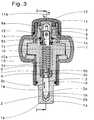
- Fig. 3 shows a cross section through a ratchet head with Square insert according to the invention, according to the one shown in FIG. 1 Section plane III - III which contains the axis of the square insert runs perpendicular to the axis of the locking pin.
- the approach 1 which is moved by the lever of the ratchet wrench, is with its tooth crown 1c rotatable inside the head part 10 of the ratchet lever stored.
- the tooth crown 1c is through the ring 10a, in which the bearing bush 13 is used for the approach 1, kept in their storage; at the the opposite side is the bearing through the narrower bore on the head 10 of the ratchet lever.
- the entire ratchet lever including the head part 10, the ring 10a and the bushings 9, 13 is made with a layer 14 Insulation material covered.
- the approach 1 ends at the opposite end with the tooth crown 1c in one Square insert 1a which is a transverse blind hole 1b for the Includes the locking pin 2b sliding therein.
- the Approach 1 and the Insert square 1a have an axial blind hole 1d with a larger one Diameter and 1e with a smaller diameter.
- the bore is an axially displaceable 3c mandrel 3 which a has conical end 3a, which in the corresponding conical seat 2b Locking pin 2 engages.
- the taper of the seat 2b and the conical end 2a is dimensioned so that a self-locking effect, in relation to the Sliding back 2c of the locking pin 2 is reached as soon as this Force components are exposed which arise from the deduction loads on attached tool result by the engagement of the ball dome 2a of the Locking pin 2 is held in one of the recesses on the insert seat.
- Said Taper is also such that self-locking in everyone Extending position of the locking pin 2 takes place regardless of the depth, width and / or position of the recess in which engages the locking pin and thereby the opposite surface of the Square to the corresponding surface of the operational seat on the patch Tool presses.
- This spring 6 is inserted over the actuating pin 5 which, by means of two semicircular shells 4, with the mandrel 3 is coupled.
- the shells 4 form together with the projecting edges 3b and 5b, a clutch for the purpose exclusive transmission of the longitudinal movement 5b to the mandrel 3, without Transmission of the rotary movement 11a and the movement of the tool itself.
- the rotary movement 11a is transmitted to the pin 5 by means of the rotary handle 11 which a coaxial, provided with vertical guide grooves, bushing 12 connected is;
- the protruding parts of a pin 5 engage in the guide grooves a transversely penetrating, firmly connected mandrel 8 in the end region.
- the axial sliding path 3c of the mandrel 3 is dimensioned so that the cone 3a is not is completely pulled out of the seat 2b on the locking pin 2, causing it is retained in its seat 1b in the insert square in each actuation chamfer.
- the invention does not rule out the use of actuation mechanisms other than those shown here, although the ones shown here are particularly suitable in the case of tools which are used in the electrical field because they ensure the insulation properties throughout the entire phase of actuation.
- the cone 3a can also be replaced by a wedge which engages in a corresponding seat on the locking pin 2.
Landscapes
- Engineering & Computer Science (AREA)
- Mechanical Engineering (AREA)
- Snaps, Bayonet Connections, Set Pins, And Snap Rings (AREA)
- Accommodation For Nursing Or Treatment Tables (AREA)
- Conveying And Assembling Of Building Elements In Situ (AREA)
- Joining Of Building Structures In Genera (AREA)
- Details Of Spanners, Wrenches, And Screw Drivers And Accessories (AREA)
- Manufacturing Of Electrical Connectors (AREA)
- Flanged Joints, Insulating Joints, And Other Joints (AREA)
- Clamps And Clips (AREA)
- Mutual Connection Of Rods And Tubes (AREA)
Abstract
Description
Der beschriebene Mechanismus eignet sich insbesondere für Ratschenschlüssel (Knarre oder Ratsche) für Einsatzwerkzeuge und Werkzeugverlängerungen.
Erfindungsgemäß kann der Konus 3a auch durch einen Keil ersetzt werden welcher in einen entsprechenden Sitz am Arretierstift 2 eingreift.
Claims (7)
- Kupplungsstück, insbesondere Einsatzvierkant, zur lösbaren Verbindung an Werkzeugen welcher einen quer zur Achse des Vierkantes gleitenden (2c) Arretierstift (2) aufweist, der durch Verschieben (3c) eines im Vierkant achsial gelagerten Dornes (3) betätigt wird, dadurch gekennzeichnet, daß die Ausfahrbewegung (2c) des Arretierstiftes (2) durch das progressive Einschieben (3c) des konischen Endes (3a) des Dornes (3) in den entsprechenden konischen Sitz (2b) am Arretierstift (2), dessen Achse orthogonal zur Achse des Sitzes angeordnet ist, erfolgt und daß, um das freie Zurückgleiten (2c) des Arretierstiftes (2) in seinen Sitz (1b) im Einsatzvierkant (1a) zu ermöglichen, der Konus (3a) aus dem Sitz (2b) am Arretierstift nur so weit herausgezogen (3c) wird, daß der Konus noch mit seinem Ende in diesen Sitz (2b) eingreift.
- Kupplungsstück, insbesondere Einsatzvierkant gemäß Patentanspruch 1, dadurch gekennzeichnet, daß die Konizität des Konus (3a) am Ende des verschiebbaren Dornes (3) und jene des entsprechenden konischen Sitzes (2b) so bemessen ist, daß am Arretierstift (2) eine selbsthemmende Wirkung was das Zurückgleiten (2c) in den Sitz (1b) am Vierkant betrifft auftritt und daß diese selbstshemmende Wirkung auch bei nur teilweise in den entsprechenden Sitz (2b) eingeschobenem Konus (3a) auftritt.
- Kupplungsstück, insbesondere Einsatzvierkant gemäß dem Patentanspruch 1, dadurch gekennzeichnet, daß anstatt des Konus (3a) ein Keil vorgesehen ist welcher in einen entsprechenden Sitz am Arretierstift (2) eingreift.
- Kupplungsstück, insbesondere Einsatzvierkant gemäß den Patentansprüchen 1, 2 oder 3, dadurch gekennzeichnet, daß die achsiale Verstellung (3c) des verschiebbaren Dornes (3) mit Konus (3a) auf direkte Weise, durch Einsatz einer Feder (6) erfolgt oder auf indirekte Weise, durch Einsatz eines Mechanismus mit schraubenförmig angeordneten Führungen (9a) erfolgt welche koachsial zum Einsatzvierkant angeordnet sind um die Drehbewegung (11a) eines Griffes (11) in eine geradlinige achsiale Bewegung umzuwandeln.
- Kupplungsstück, insbesondere Einsatzvierkant gemäß den Patentansprüchen von 1 bis 4, dadurch gekennzeichnet, daß zwischen dem Antriebselement (10) für den Einsatzvierkant (1a), beziehungsweise zwischen der Isolationsschicht (14) welche dieses Antriebselement umhüllt und der Innenfläche des Griffes (11), Dichtungselemente (15) vorgesehen sind.
- Einsatzvierkant gemäß den Patentansprüchen von 1 bis 3, dadurch gekennzeichnet, daß zwischen dem Mechanismus zur Umwandlung der Drehbewegung (11a) des Griffes (11) in eine geradlinige Bewegung (5b - 3c) und dem Dorn (3) mit Konus (3a), ein Kupplungselement (4) vorgesehen ist welches nur die Längsbewegung, nicht die Drehbewegung (11a), auf den Dorn (3) überträgt.
- Einsatzvierkant gemäß den Patentansprüchen von 1 bis 3, dadurch gekennzeichnet, daß der Mechanismus zur Umwandlung der Drehbewegung (11a) des Griffes (11) in eine geradlinige Bewegung (3c) des Dornes (3) mit Konus (3a) direkt auf diesen Dorn (3) wirkt welcher achsial geführt ist um die Übertragung einer Drehung, welche von einer mit schraubenförmig angeordneten Führungen versehenen Buchse ausgeführt wird, während der Verschiebung (3c) zu verhindern.
Applications Claiming Priority (2)
| Application Number | Priority Date | Filing Date | Title |
|---|---|---|---|
| ITBZ970032 | 1997-06-11 | ||
| IT97BZ000032A IT1292554B1 (it) | 1997-06-11 | 1997-06-11 | Quadro di trascinamento per attrezzi ad accoppiamento bloccabile |
Publications (3)
| Publication Number | Publication Date |
|---|---|
| EP0884137A2 true EP0884137A2 (de) | 1998-12-16 |
| EP0884137A3 EP0884137A3 (de) | 2001-05-09 |
| EP0884137B1 EP0884137B1 (de) | 2003-09-03 |
Family
ID=11346806
Family Applications (1)
| Application Number | Title | Priority Date | Filing Date |
|---|---|---|---|
| EP98109971A Expired - Lifetime EP0884137B1 (de) | 1997-06-11 | 1998-06-02 | Kupplungsstück für lösbare Verbindung an Werkzeugen |
Country Status (4)
| Country | Link |
|---|---|
| EP (1) | EP0884137B1 (de) |
| AT (1) | ATE248685T1 (de) |
| DE (1) | DE59809453D1 (de) |
| IT (1) | IT1292554B1 (de) |
Cited By (2)
| Publication number | Priority date | Publication date | Assignee | Title |
|---|---|---|---|---|
| DE10036224C1 (de) * | 2000-07-26 | 2002-06-13 | Uwe Spaeth | Verbindungsstück zwischen einem Vorwerkzeug und einem Folgewerkzeug |
| EP3002083A1 (de) * | 2014-10-03 | 2016-04-06 | Stanley Chiro International Ltd. | Ratschenschlüssel |
Families Citing this family (1)
| Publication number | Priority date | Publication date | Assignee | Title |
|---|---|---|---|---|
| DE102022113887B4 (de) | 2022-06-01 | 2024-04-25 | Wiha Werkzeuge Gmbh | Isoliertes Drehwerkzeug |
Family Cites Families (5)
| Publication number | Priority date | Publication date | Assignee | Title |
|---|---|---|---|---|
| US2954994A (en) * | 1957-12-23 | 1960-10-04 | Chicago Pneumatic Tool Co | Socket retainer for rotary power tools |
| US3180435A (en) * | 1962-05-25 | 1965-04-27 | Chicago Pneumatic Tool Co | Socket retainer for impact wrench |
| US3762245A (en) * | 1971-04-08 | 1973-10-02 | Litton Industrial Products | Quick release and speeder for socket wrench |
| US4794828A (en) * | 1983-12-19 | 1989-01-03 | Snap-On Tools Corporation | Quick release mechanism for ratchet wrench |
| DE8909646U1 (de) * | 1989-08-11 | 1990-12-06 | Werkzeugfabrik G. Adolf Lemp & Co, 5630 Remscheid | Aufsteckwerkzeug |
-
1997
- 1997-06-11 IT IT97BZ000032A patent/IT1292554B1/it active IP Right Grant
-
1998
- 1998-06-02 AT AT98109971T patent/ATE248685T1/de not_active IP Right Cessation
- 1998-06-02 EP EP98109971A patent/EP0884137B1/de not_active Expired - Lifetime
- 1998-06-02 DE DE59809453T patent/DE59809453D1/de not_active Expired - Lifetime
Cited By (2)
| Publication number | Priority date | Publication date | Assignee | Title |
|---|---|---|---|---|
| DE10036224C1 (de) * | 2000-07-26 | 2002-06-13 | Uwe Spaeth | Verbindungsstück zwischen einem Vorwerkzeug und einem Folgewerkzeug |
| EP3002083A1 (de) * | 2014-10-03 | 2016-04-06 | Stanley Chiro International Ltd. | Ratschenschlüssel |
Also Published As
| Publication number | Publication date |
|---|---|
| ATE248685T1 (de) | 2003-09-15 |
| DE59809453D1 (de) | 2003-10-09 |
| IT1292554B1 (it) | 1999-02-08 |
| EP0884137B1 (de) | 2003-09-03 |
| ITBZ970032A0 (de) | 1997-06-11 |
| EP0884137A3 (de) | 2001-05-09 |
| ITBZ970032A1 (it) | 1998-12-11 |
Similar Documents
| Publication | Publication Date | Title |
|---|---|---|
| DE60104177T2 (de) | Spindeleinheit für Lochsäge und Bohrer | |
| DE69920523T2 (de) | Spannfutter | |
| DE69407775T2 (de) | Schraubenzieher mit einrichtung für austauschbare einsätze | |
| EP3025807B1 (de) | Nietwerkzeug | |
| DE60037950T2 (de) | Bohrantrieb Futter | |
| DE10109364A1 (de) | Handwerkzeug | |
| DE20209159U1 (de) | Schnellsicherung für Verlängerungen von Steckwerkzeugen | |
| EP2851155A2 (de) | Ratsche mit Feinverzahnung | |
| DE3419687A1 (de) | Vorrichtung zum setzen einer hutmutter | |
| DE3804129A1 (de) | Verbesserte steckschluesselverlaengerung | |
| WO2009015932A1 (de) | Handwerkzeugmaschine mit einem werkzeughalter | |
| DE60001337T2 (de) | Bohrfutter | |
| EP0827796A1 (de) | Löseeinheit | |
| DE2224525A1 (de) | Revolverkopf für Werkzeuge zur Herstellung elektrischer Quetschverbindungen | |
| EP0884137B1 (de) | Kupplungsstück für lösbare Verbindung an Werkzeugen | |
| EP3025824A1 (de) | Mobiles hydraulikwerkzeug | |
| DE10061461B4 (de) | Bithalter | |
| DE19610213A1 (de) | Spannfutter mit Bogenstück | |
| EP3147053A1 (de) | Spannfutter | |
| DE19634707A1 (de) | Bohrer | |
| EP1709930A1 (de) | Motorelement, insbesondere medizinisches Handstück mit einer Spannzange | |
| DE2162090A1 (de) | Ausriickbare Mitnehmervorrichtung | |
| EP2777850B1 (de) | Spann- oder Greifeinrichtung | |
| DE29604499U1 (de) | Entriegelungswerkzeug | |
| DE29505752U1 (de) | Vorrichtung zum Verbinden von Platten mittels Verschraubung |
Legal Events
| Date | Code | Title | Description |
|---|---|---|---|
| PUAI | Public reference made under article 153(3) epc to a published international application that has entered the european phase |
Free format text: ORIGINAL CODE: 0009012 |
|
| AK | Designated contracting states |
Kind code of ref document: A2 Designated state(s): AT CH DE DK ES FI FR GB GR IT LI SE |
|
| AX | Request for extension of the european patent |
Free format text: AL;LT;LV;MK;RO;SI |
|
| PUAL | Search report despatched |
Free format text: ORIGINAL CODE: 0009013 |
|
| AK | Designated contracting states |
Kind code of ref document: A3 Designated state(s): AT BE CH CY DE DK ES FI FR GB GR IE IT LI LU MC NL PT SE |
|
| AX | Request for extension of the european patent |
Free format text: AL;LT PAYMENT 19980611;LV;MK;RO;SI PAYMENT 19980611 |
|
| 17P | Request for examination filed |
Effective date: 20011107 |
|
| AKX | Designation fees paid |
Free format text: AT CH DE DK ES FI FR GB GR IT LI SE |
|
| AXX | Extension fees paid |
Free format text: LT PAYMENT 19980611;SI PAYMENT 19980611 |
|
| 17Q | First examination report despatched |
Effective date: 20020925 |
|
| GRAH | Despatch of communication of intention to grant a patent |
Free format text: ORIGINAL CODE: EPIDOS IGRA |
|
| GRAH | Despatch of communication of intention to grant a patent |
Free format text: ORIGINAL CODE: EPIDOS IGRA |
|
| GRAA | (expected) grant |
Free format text: ORIGINAL CODE: 0009210 |
|
| RAX | Requested extension states of the european patent have changed |
Extension state: SI Payment date: 19980611 |
|
| AK | Designated contracting states |
Kind code of ref document: B1 Designated state(s): AT CH DE DK ES FI FR GB GR IT LI SE |
|
| AX | Request for extension of the european patent |
Extension state: SI |
|
| PG25 | Lapsed in a contracting state [announced via postgrant information from national office to epo] |
Ref country code: GB Free format text: LAPSE BECAUSE OF FAILURE TO SUBMIT A TRANSLATION OF THE DESCRIPTION OR TO PAY THE FEE WITHIN THE PRESCRIBED TIME-LIMIT Effective date: 20030903 Ref country code: FI Free format text: LAPSE BECAUSE OF FAILURE TO SUBMIT A TRANSLATION OF THE DESCRIPTION OR TO PAY THE FEE WITHIN THE PRESCRIBED TIME-LIMIT Effective date: 20030903 |
|
| REG | Reference to a national code |
Ref country code: GB Ref legal event code: FG4D Free format text: NOT ENGLISH |
|
| REG | Reference to a national code |
Ref country code: CH Ref legal event code: EP |
|
| REF | Corresponds to: |
Ref document number: 59809453 Country of ref document: DE Date of ref document: 20031009 Kind code of ref document: P |
|
| PG25 | Lapsed in a contracting state [announced via postgrant information from national office to epo] |
Ref country code: SE Free format text: LAPSE BECAUSE OF FAILURE TO SUBMIT A TRANSLATION OF THE DESCRIPTION OR TO PAY THE FEE WITHIN THE PRESCRIBED TIME-LIMIT Effective date: 20031203 Ref country code: GR Free format text: LAPSE BECAUSE OF FAILURE TO SUBMIT A TRANSLATION OF THE DESCRIPTION OR TO PAY THE FEE WITHIN THE PRESCRIBED TIME-LIMIT Effective date: 20031203 Ref country code: DK Free format text: LAPSE BECAUSE OF FAILURE TO SUBMIT A TRANSLATION OF THE DESCRIPTION OR TO PAY THE FEE WITHIN THE PRESCRIBED TIME-LIMIT Effective date: 20031203 |
|
| PG25 | Lapsed in a contracting state [announced via postgrant information from national office to epo] |
Ref country code: ES Free format text: LAPSE BECAUSE OF FAILURE TO SUBMIT A TRANSLATION OF THE DESCRIPTION OR TO PAY THE FEE WITHIN THE PRESCRIBED TIME-LIMIT Effective date: 20031214 |
|
| GBV | Gb: ep patent (uk) treated as always having been void in accordance with gb section 77(7)/1977 [no translation filed] |
Effective date: 20030903 |
|
| PG25 | Lapsed in a contracting state [announced via postgrant information from national office to epo] |
Ref country code: AT Free format text: LAPSE BECAUSE OF NON-PAYMENT OF DUE FEES Effective date: 20040602 |
|
| PG25 | Lapsed in a contracting state [announced via postgrant information from national office to epo] |
Ref country code: LI Free format text: LAPSE BECAUSE OF NON-PAYMENT OF DUE FEES Effective date: 20040630 Ref country code: CH Free format text: LAPSE BECAUSE OF NON-PAYMENT OF DUE FEES Effective date: 20040630 |
|
| ET | Fr: translation filed | ||
| PLBE | No opposition filed within time limit |
Free format text: ORIGINAL CODE: 0009261 |
|
| STAA | Information on the status of an ep patent application or granted ep patent |
Free format text: STATUS: NO OPPOSITION FILED WITHIN TIME LIMIT |
|
| 26N | No opposition filed |
Effective date: 20040604 |
|
| REG | Reference to a national code |
Ref country code: CH Ref legal event code: PL |
|
| REG | Reference to a national code |
Ref country code: FR Ref legal event code: PLFP Year of fee payment: 18 |
|
| PG25 | Lapsed in a contracting state [announced via postgrant information from national office to epo] |
Ref country code: IT Free format text: LAPSE BECAUSE OF NON-PAYMENT OF DUE FEES Effective date: 20150602 |
|
| PGRI | Patent reinstated in contracting state [announced from national office to epo] |
Ref country code: IT Effective date: 20160412 |
|
| REG | Reference to a national code |
Ref country code: FR Ref legal event code: PLFP Year of fee payment: 19 |
|
| REG | Reference to a national code |
Ref country code: FR Ref legal event code: PLFP Year of fee payment: 20 |
|
| PGFP | Annual fee paid to national office [announced via postgrant information from national office to epo] |
Ref country code: FR Payment date: 20170630 Year of fee payment: 20 |
|
| PGFP | Annual fee paid to national office [announced via postgrant information from national office to epo] |
Ref country code: IT Payment date: 20170621 Year of fee payment: 20 |
|
| PGFP | Annual fee paid to national office [announced via postgrant information from national office to epo] |
Ref country code: DE Payment date: 20170628 Year of fee payment: 20 |
|
| REG | Reference to a national code |
Ref country code: DE Ref legal event code: R071 Ref document number: 59809453 Country of ref document: DE |