EP0884169B1 - Reifenbestandteil aus Gummi und Verfahren zu seiner Herstellung - Google Patents
Reifenbestandteil aus Gummi und Verfahren zu seiner Herstellung Download PDFInfo
- Publication number
- EP0884169B1 EP0884169B1 EP98304628A EP98304628A EP0884169B1 EP 0884169 B1 EP0884169 B1 EP 0884169B1 EP 98304628 A EP98304628 A EP 98304628A EP 98304628 A EP98304628 A EP 98304628A EP 0884169 B1 EP0884169 B1 EP 0884169B1
- Authority
- EP
- European Patent Office
- Prior art keywords
- apex
- tyre
- rubber
- rubber element
- generally
- Prior art date
- Legal status (The legal status is an assumption and is not a legal conclusion. Google has not performed a legal analysis and makes no representation as to the accuracy of the status listed.)
- Expired - Lifetime
Links
- 238000004519 manufacturing process Methods 0.000 title claims description 34
- 239000011324 bead Substances 0.000 claims description 29
- 238000000465 moulding Methods 0.000 claims description 2
- 238000003825 pressing Methods 0.000 claims description 2
- 238000000034 method Methods 0.000 description 17
- 230000002950 deficient Effects 0.000 description 12
- 238000001125 extrusion Methods 0.000 description 4
- 239000000463 material Substances 0.000 description 3
- 238000000926 separation method Methods 0.000 description 3
- 230000004323 axial length Effects 0.000 description 2
- 238000005452 bending Methods 0.000 description 2
- 230000003247 decreasing effect Effects 0.000 description 2
- 239000000945 filler Substances 0.000 description 2
- 238000005304 joining Methods 0.000 description 2
- 230000002787 reinforcement Effects 0.000 description 2
- 230000000630 rising effect Effects 0.000 description 2
- 239000003351 stiffener Substances 0.000 description 2
- 238000007796 conventional method Methods 0.000 description 1
- 238000005520 cutting process Methods 0.000 description 1
- 230000003014 reinforcing effect Effects 0.000 description 1
Images




Classifications
-
- B—PERFORMING OPERATIONS; TRANSPORTING
- B60—VEHICLES IN GENERAL
- B60C—VEHICLE TYRES; TYRE INFLATION; TYRE CHANGING; CONNECTING VALVES TO INFLATABLE ELASTIC BODIES IN GENERAL; DEVICES OR ARRANGEMENTS RELATED TO TYRES
- B60C15/00—Tyre beads, e.g. ply turn-up or overlap
- B60C15/06—Flipper strips, fillers, or chafing strips and reinforcing layers for the construction of the bead
-
- B—PERFORMING OPERATIONS; TRANSPORTING
- B29—WORKING OF PLASTICS; WORKING OF SUBSTANCES IN A PLASTIC STATE IN GENERAL
- B29D—PRODUCING PARTICULAR ARTICLES FROM PLASTICS OR FROM SUBSTANCES IN A PLASTIC STATE
- B29D30/00—Producing pneumatic or solid tyres or parts thereof
- B29D30/06—Pneumatic tyres or parts thereof (e.g. produced by casting, moulding, compression moulding, injection moulding, centrifugal casting)
- B29D30/48—Bead-rings or bead-cores; Treatment thereof prior to building the tyre
-
- B—PERFORMING OPERATIONS; TRANSPORTING
- B60—VEHICLES IN GENERAL
- B60C—VEHICLE TYRES; TYRE INFLATION; TYRE CHANGING; CONNECTING VALVES TO INFLATABLE ELASTIC BODIES IN GENERAL; DEVICES OR ARRANGEMENTS RELATED TO TYRES
- B60C15/00—Tyre beads, e.g. ply turn-up or overlap
- B60C15/04—Bead cores
-
- B—PERFORMING OPERATIONS; TRANSPORTING
- B29—WORKING OF PLASTICS; WORKING OF SUBSTANCES IN A PLASTIC STATE IN GENERAL
- B29D—PRODUCING PARTICULAR ARTICLES FROM PLASTICS OR FROM SUBSTANCES IN A PLASTIC STATE
- B29D30/00—Producing pneumatic or solid tyres or parts thereof
- B29D30/06—Pneumatic tyres or parts thereof (e.g. produced by casting, moulding, compression moulding, injection moulding, centrifugal casting)
- B29D30/48—Bead-rings or bead-cores; Treatment thereof prior to building the tyre
- B29D2030/482—Applying fillers or apexes to bead cores
-
- Y—GENERAL TAGGING OF NEW TECHNOLOGICAL DEVELOPMENTS; GENERAL TAGGING OF CROSS-SECTIONAL TECHNOLOGIES SPANNING OVER SEVERAL SECTIONS OF THE IPC; TECHNICAL SUBJECTS COVERED BY FORMER USPC CROSS-REFERENCE ART COLLECTIONS [XRACs] AND DIGESTS
- Y10—TECHNICAL SUBJECTS COVERED BY FORMER USPC
- Y10T—TECHNICAL SUBJECTS COVERED BY FORMER US CLASSIFICATION
- Y10T152/00—Resilient tires and wheels
- Y10T152/10—Tires, resilient
- Y10T152/10495—Pneumatic tire or inner tube
- Y10T152/10819—Characterized by the structure of the bead portion of the tire
- Y10T152/10837—Bead characterized by the radial extent of apex, flipper or chafer into tire sidewall
-
- Y—GENERAL TAGGING OF NEW TECHNOLOGICAL DEVELOPMENTS; GENERAL TAGGING OF CROSS-SECTIONAL TECHNOLOGIES SPANNING OVER SEVERAL SECTIONS OF THE IPC; TECHNICAL SUBJECTS COVERED BY FORMER USPC CROSS-REFERENCE ART COLLECTIONS [XRACs] AND DIGESTS
- Y10—TECHNICAL SUBJECTS COVERED BY FORMER USPC
- Y10T—TECHNICAL SUBJECTS COVERED BY FORMER US CLASSIFICATION
- Y10T152/00—Resilient tires and wheels
- Y10T152/10—Tires, resilient
- Y10T152/10495—Pneumatic tire or inner tube
- Y10T152/10819—Characterized by the structure of the bead portion of the tire
- Y10T152/10846—Bead characterized by the chemical composition and or physical properties of elastomers or the like
Definitions
- This invention relates to a rubber element for a tyre and a method of manufacturing the same.
- a subassembly 113 comprising a rubber apex 102 attached to a bead core 101.
- the apex 102 has a cross-sectional configuration which is generally a triangle as shown in Figure 5A.
- An alternative prior art element 113 comprising a bead core 101 and an apex (which is a bead filler or a stiffener) 103 whose cross-sectional configuration is generally a trapezoid and which is attached to the bead core 101 is shown in Figure 6.
- a carcass inner component 112 comprising layers of an inner liner and a reinforcement ply is wrapped around a cylindrical former 104 and at each side of the former a rubber element 113 is positioned over the edge. Then the apex 102 is bent over, i.e. the apex 102 is shaped onto the former 104 as shown in Figure 5B. To bend the apex 102 on its side, the apex 102 is pressed down with a relatively high pressure by, for example, a stitcher, and this process is bothersome.
- the apex 103 of the rubber element for the tyre shown in Figure 6 does not need to be bent down to the former in the process of manufacturing a tyre, however the inclined side face 111 of the apex 103 does not fit to the sheet-like member 112 which is the reinforcement ply, and the apex 103 and the bead core 101 to which the apex 103 is attached slip down their initial fixed position on the sheet-like member 112.
- First sheet-like rubber material 105 is formed as shown in Figure 7, then the rubber material 105 is cut to form an apex 103 whose cross-sectional configuration is generally a trapezoid. This is then attached to the bead core 101.
- This manufacturing method requires the bothersome operations above, and by manufacturing the rubber element by the conventional method, some parts of the material are left unused and are wasted.
- An apex whose sectional configuration is generally a trapezoid is moulded by an extrusion machine in some cases, however, this rubber extruded from a die plate of the extrusion machine is often twisted and it is not possible to straighten it.
- a rubber element for a tyre which comprises a bead core and an apex whose inner face is attached to an outer circumferential face of said bead core, is characterised by said apex having a cross-sectional configuration which is generally a rectangle whose two corners on the outer circumference of said apex are rounded off.
- the corners may be rounded off to give a cross-section which is generally a semi-ellipse or a semi-circle.
- the rubber apex has a hardness in the range of JIS A 83° to 98°.
- Another aspect of the invention provides a method of manufacturing a rubber element for a tyre.
- Figure 1A shows a rubber element 18 for a tyre according to the present invention which comprises a bead core 1 and an apex 2 (which can be called a bead filler or a stiffener) attached to the bead core 1.
- apex 2 which can be called a bead filler or a stiffener
- the apex 2 of this invention has a cross-sectional configuration which is generally a rectangle whose two corners on the outer circumference of the apex are rounded off i.e. it is generally D-shaped in cross section.
- the apex 2 comprises a first portion 3 whose cross-sectional configuration is generally a rectangle, and second portion 4 whose cross-sectional configuration is generally a semi-ellipse (which is divided by a major axis of an ellipse) and integrally moulded on an outer circumference of the first portion 3, and both of side faces of the apex 2 are planes which are parallel.
- the apex has a cross-sectional configuration which a combination of a first portion 3 whose cross-sectional configuration is generally a square and a second portion 4 whose cross-sectional configuration is generally a semi-ellipse.
- the apex has a cross-sectional configuration which a combination of a first portion 3 whose cross-sectional configuration is generally a rectangle and a second portion 4 whose cross-sectional configuration is generally a semi-circle.
- the apex has a cross-sectional configuration which a combination of a first portion 3 whose cross-sectional configuration is generally a square and a second portion 4 whose cross-sectional configuration is generally a semi-circle.
- the rubber hardness of this apex 2 is arranged to be JIS (Japanese Industrial Standard) A 83° to 98°.
- JIS Japanese Industrial Standard
- an axial length of an inner face 15 (which corresponds to an axial length A 1 of the bead core 1) is expressed by 'A'
- the height (radial length) of the apex is expressed by 'B'
- a linear rubber body 5 whose sectional configuration is a circle is formed by extrusion, and by cutting the linear body 5 to a predetermined length so that a linear rubber body 5a of predetermined length is results. After that, the rubber body 5a is attached to the bead core 1 which is a ring shape as shown in Figure 3.
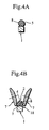
- the rubber element 18 for a tyre manufacture by the method described above is fitted to the edges of a sheet-like member 20, indicated in the Figures by alternate long and two short dashes lines and comprising layers of an inner liner and a carcass reinforcing ply, on a former 10 (see Figure 1A). That is to say, the sheet-like member 20 is wrapped around the former 10, the rubber element 18 is positioned over a turned-down edge, and then the member 20 is 'turned-up' around the rubber element 18.
- the side face of the apex 2, i.e. the side face of the first position 3 is not inclined towards the end face 11 of the former 10 and so the liner ply assembly is prevented from 'partial rising', and inferiority in adhesion of the apex to the sheet-like member is not caused. Consequently the bead portion of the finished tyre can be assembled to a rim so that the bead portion and the rim form a full circular configuration, thereby RFV (Radial Force Variation) of the tyre can be decreased.
- the apex of the present invention does not need to be bent over, whereas in the prior art each apex 102 shown in Figures 5A to 5C whose sectional configuration is generally a triangular configuration and needs to be bent down. Thereby the force required to bend down the apex is not needed when moulding the tyre with the rubber element of the present invention, and 'crack (separation)' is not caused between the bead core 1 and the apex 2.
- the linear body 5 forming the linear rubber body 5a is a rubber product whose sectional configuration is a circle (which is an identical configuration with a screw for extrusion), a linear rubber body 5a of high quality can be manufactured even if the linear body 5 which is extruded is twisted.
- the apex 2 is a rubber having a hardness of JIS A 83° to 98° and the apex shows great strength.
- rubber elements 113 having apexes 102 were manufactured as Conventional Product 1
- rubber elements 113 for a tyre having apexes 103, each of which is generally a trapezoid configuration in section were manufactured as Conventional Product 2
- rubber elements 18 for a tyre having apexes 2 each of which has a sectional configuration illustrated in Figure 1A were manufactured as Product (Example) of the present invention.
- Tyres were manufactured with the respective rubber elements. The results of manufacturing the tyres are shown in Table 1.
- the size of the rubber elements for tyres is 145R12, and 100 pieces of rubber elements for tyres were respectively manufactured as the Conventional Products 1, the Conventional Products 2, and the Products of the Present Invention.
- Conventional Product 1 Conventional Product 2
- Manufacturing Rate of Defective Products % 5 7 0 Productivity Index 100 80 70
- Each 'Productivity Index' shows the time expressed as percentages which is required to form a tyre when manufacturing a tyre with a conventional product 2 or a product of the present invention based on the time of manufacturing a tyre with a conventional product 1 to be '100'.
- an apex-down process and a ply-stitch process (a process to release remained air generated in the process of assembling an element to a ply, and the process to stitch a ply by a ply-stitcher) are required.
- a ply-stitch process is required, and in the case of manufacturing a tyres using a product of the present invention, neither apex-down process nor a ply-stitch process is required.
- the productivity index of the case of manufacturing a tyre with the conventional product 1 is arranged to be '100', in the case of manufacturing a tyre with the conventional product 2, a tyre is manufactured in 80% of the time required to manufacture a tyre with the conventional product 1.
- a tyre is manufactured in 70% of the time required to manufacture a tyre with the conventional product 1.
- the rubber element for a tyre according to the present invention allows the omission of the step of laying down the apex when manufacturing a tyre with the rubber element of the present invention (while the conventional case using the apex whose sectional configuration is generally a triangle needs to be bent down). As a result, the whole manufacturing process time can be shortened.
- a tyre which is formed with a rubber element for a tyre according to the present invention inferiority in adhesion of apex to sheet-like member is not caused, and the bead portion of the finished tyre can be assembled to a rim so that the bead portion and the rim form a full circle configuration, thereby RFV (Radial Force Variation) of the tyre can be decreased.
- RFV Ring Force Variation
- the process to bend down an apex is omitted and 'crack (separation)' is not be caused at the joining face between the bead core 1 and the apex 2, and defective tyres are not manufactured.
- the hardness of an apex 2 is adequate and inferiority in adhesion of its apex to the sheet-like member is prevented from occurring.
- a rubber element for a tyre which increases productivity of tyre, and which is surely prevented from producing defective tyre, can be easily manufactured with accuracy.
Landscapes
- Engineering & Computer Science (AREA)
- Mechanical Engineering (AREA)
- Tyre Moulding (AREA)
- Tires In General (AREA)
Claims (5)
- Kautschukelement für einen Reifen, das einen Wulstkern (1) und einen Kernreiter (2) umfasst, dessen Innenfläche (15) an einer Außenumfangsfläche (8) des Wulstkerns (1) angebracht ist, dadurch gekennzeichnet, dass der Kernreiter (2) eine Querschnittsform aufweist, die im Allgemeinen ein Rechteck ist, dessen beide Ecken am Außenumfang des Kernreiters (2) abgerundet sind.
- Kautschukelement nach Anspruch 1, dadurch gekennzeichnet, dass die Ecken aneinander abgerundet sind und der Kernreiter (2) einen ersten Abschnitt (3); dessen Querschnittsform im Allgemeinen ein Rechteck ist, und einen zweiten Abschnitt (4) umfasst, dessen Querschnittsform im Allgemeinen eine Halbellipse ist, und der einstückig an einem Außenumfang des ersten Abschnitts (3) angeformt ist, und dass eine Innenfläche (15) des ersten Abschnitts (3) des Kernreiters (2) an einer Außenumfangsfläche (8) des Wulstkerns (1) angebracht ist.
- Kautschukelement nach Anspruch 1, dadurch gekennzeichnet, dass die Ecken aneinander abgerundet sind und der Kernreiter (2) einen ersten Abschnitt (3), dessen Querschnittsform im Allgemeinen ein Rechteck ist, und einen zweiten Abschnitt (4) umfasst, dessen Querschnittsform im Allgemeinen ein Halbkreis ist, und der einstückig an einem Außenumfang des ersten Abschnitts (3) angeformt ist, und dass eine Innenfläche (15) des ersten Abschnitts (3) des Kernreiters (2) an einer Außenumfangsfläche (8) des Wulstkerns (1) angebracht ist.
- Kautschukelement nach einem der Ansprüche 1 bis 3, dadurch gekennzeichnet, dass die Gummihärte des Kernreiters (2) derart eingerichtet ist, dass sie nach JIS A 83° bis 98° beträgt.
- Verfahren zum Herstellen eines Kautschukeiements für einen Reifen, gekennzeichnet durch die Schritte, dass ein gerader Kautschukkörper (5a) mit einer vorbestimmten Länge geformt wird, um einen Kernreiter mit einer im Querschnitt kreisförmigen Form zu bilden, der gerade Kautschukkörper (5a) durch Befestigungswalzen (7) gepresst wird, um den Kernreiter (2) zu bilden, der eine Querschnittsform aufweist, die im Allgemeinen ein Rechteck ist, dessen beide Ecken am Außenumfang des Kernreiters (2) abgerundet sind, und der Kernreiter (2) an einem Wulstkern (1) angebracht wird.
Applications Claiming Priority (3)
| Application Number | Priority Date | Filing Date | Title |
|---|---|---|---|
| JP173216/97 | 1997-06-13 | ||
| JP17321697 | 1997-06-13 | ||
| JP17321697A JP3299693B2 (ja) | 1997-06-13 | 1997-06-13 | タイヤ用ゴム材料の製造方法 |
Publications (3)
| Publication Number | Publication Date |
|---|---|
| EP0884169A2 EP0884169A2 (de) | 1998-12-16 |
| EP0884169A3 EP0884169A3 (de) | 1999-12-15 |
| EP0884169B1 true EP0884169B1 (de) | 2002-12-04 |
Family
ID=15956290
Family Applications (1)
| Application Number | Title | Priority Date | Filing Date |
|---|---|---|---|
| EP98304628A Expired - Lifetime EP0884169B1 (de) | 1997-06-13 | 1998-06-11 | Reifenbestandteil aus Gummi und Verfahren zu seiner Herstellung |
Country Status (4)
| Country | Link |
|---|---|
| US (1) | US6089294A (de) |
| EP (1) | EP0884169B1 (de) |
| JP (1) | JP3299693B2 (de) |
| DE (1) | DE69809840T2 (de) |
Families Citing this family (4)
| Publication number | Priority date | Publication date | Assignee | Title |
|---|---|---|---|---|
| NL2007414C2 (en) | 2011-09-14 | 2013-03-18 | Robert Wilhelmus Franke | A method of manufacturing a tire bead core assembly, a tire bead core assembly forming apparatus, a tire bead core assembly, a tire, a bead filler intermediate and a use of a compression mould. |
| ITTO20120353A1 (it) * | 2012-04-20 | 2013-10-21 | Bridgestone Europ Nv | Metodo ed impianto per la produzione di una striscia di battistrada di un pneumatico provvista di barre |
| ITTO20120354A1 (it) * | 2012-04-20 | 2013-10-21 | Bridgestone Europ Nv | Metodo ed impianto di produzione per realizzare una striscia di battistrada di un pneumatico provvista di barre |
| EP4163096B1 (de) * | 2021-10-08 | 2025-04-23 | Nokian Renkaat Oyj | Reifen mit einem tropfenförmigen wulstkern und verfahren zur herstellung |
Family Cites Families (9)
| Publication number | Priority date | Publication date | Assignee | Title |
|---|---|---|---|---|
| US1944768A (en) * | 1925-06-13 | 1934-01-23 | Firestone Tire & Rubber Co | Method of building beads for tires |
| US2000869A (en) * | 1933-07-11 | 1935-05-07 | Firestone Tire & Rubber Co | Tire construction |
| US2971553A (en) * | 1957-03-04 | 1961-02-14 | Firestone & Tire & Rubber Comp | Tire construction |
| AU7625274A (en) * | 1973-12-18 | 1976-06-10 | Avon Rubber Co Ltd | Tubeless tyres |
| DE2635233A1 (de) * | 1976-08-05 | 1978-02-09 | Continental Gummi Werke Ag | Verfahren zur herstellung von stahldrahtkernen fuer die wuelste von luftreifen |
| US4196036A (en) * | 1978-08-21 | 1980-04-01 | The B. F. Goodrich Company | Tire bead ring assembly machine |
| DE2940221C2 (de) * | 1979-10-04 | 1983-10-13 | Hahn GmbH & Co, 5992 Nachrodt | Wulstkern für schlauchlose Fahrzeugluftreifen |
| JPH0262232A (ja) * | 1988-08-29 | 1990-03-02 | Toyo Tire & Rubber Co Ltd | 自動車タイヤのビード部複合構造体の組立方法、その組立装置およびビードフィラー貼合せ装置 |
| US5203938A (en) * | 1991-01-31 | 1993-04-20 | Heico Aluminum Products, Inc. | Method and apparatus for forming an apex filler and/or applying an apex filler to a bead ring sub-assembly |
-
1997
- 1997-06-13 JP JP17321697A patent/JP3299693B2/ja not_active Expired - Fee Related
-
1998
- 1998-05-26 US US09/084,286 patent/US6089294A/en not_active Expired - Fee Related
- 1998-06-11 EP EP98304628A patent/EP0884169B1/de not_active Expired - Lifetime
- 1998-06-11 DE DE69809840T patent/DE69809840T2/de not_active Expired - Lifetime
Also Published As
| Publication number | Publication date |
|---|---|
| DE69809840T2 (de) | 2003-07-10 |
| EP0884169A3 (de) | 1999-12-15 |
| JP3299693B2 (ja) | 2002-07-08 |
| US6089294A (en) | 2000-07-18 |
| DE69809840D1 (de) | 2003-01-16 |
| EP0884169A2 (de) | 1998-12-16 |
| JPH115260A (ja) | 1999-01-12 |
Similar Documents
| Publication | Publication Date | Title |
|---|---|---|
| EP1211057B1 (de) | Verfahren zur Reifenherstellung | |
| US12539721B2 (en) | RFID package for a tire | |
| US5215612A (en) | Method for manufacturing tires | |
| EP0492504A1 (de) | Verfahren zum Herstellen eines Reifens und damit hergestellter Reifen | |
| GB2118111A (en) | Process for making a radial tyre | |
| EP0884169B1 (de) | Reifenbestandteil aus Gummi und Verfahren zu seiner Herstellung | |
| EP1551618B1 (de) | Segmentierte reifenform zur verringerung von grat | |
| JP2007152948A (ja) | ゲージの小さなタイヤプライを製造する装置および方法 | |
| JP4286511B2 (ja) | 空気入りラジアルタイヤ及びその製造方法 | |
| JP4263755B1 (ja) | 空気入りタイヤの製造方法 | |
| CN101432128A (zh) | 充气轮胎的制造方法及充气轮胎 | |
| KR101812805B1 (ko) | 공기 타이어 및 그 제조방법 | |
| US11318695B2 (en) | Tire manufacturing method and tire | |
| JP3367895B2 (ja) | 空気入りタイヤの製造方法 | |
| JP3803289B2 (ja) | タイヤ製造方法 | |
| JPH0446220B2 (de) | ||
| JP3266704B2 (ja) | タイヤ用ビード | |
| JP2014076752A (ja) | 空気入りタイヤ及び空気入りタイヤの製造方法 | |
| EP0478271B1 (de) | Verfahren und Aufbautrommel zur Herstellung eines Luftreifengürtels | |
| JP5000276B2 (ja) | 空気入りタイヤの製造方法 | |
| EP2647493B1 (de) | Reifenherstellungsverfahren | |
| WO2018016182A1 (ja) | 空気入りタイヤの製造方法、および空気入りタイヤ | |
| KR100917757B1 (ko) | 공기입 타이어의 바디플라이 접합방법 | |
| JP2009178909A (ja) | 空気入りタイヤの製造方法 | |
| JP2024100545A (ja) | タイヤ製造装置およびタイヤの製造方法 |
Legal Events
| Date | Code | Title | Description |
|---|---|---|---|
| PUAI | Public reference made under article 153(3) epc to a published international application that has entered the european phase |
Free format text: ORIGINAL CODE: 0009012 |
|
| AK | Designated contracting states |
Kind code of ref document: A2 Designated state(s): DE FR GB |
|
| AX | Request for extension of the european patent |
Free format text: AL;LT;LV;MK;RO;SI |
|
| PUAL | Search report despatched |
Free format text: ORIGINAL CODE: 0009013 |
|
| AK | Designated contracting states |
Kind code of ref document: A3 Designated state(s): AT BE CH CY DE DK ES FI FR GB GR IE IT LI LU MC NL PT SE |
|
| AX | Request for extension of the european patent |
Free format text: AL;LT;LV;MK;RO;SI |
|
| 17P | Request for examination filed |
Effective date: 20000131 |
|
| AKX | Designation fees paid |
Free format text: DE FR GB |
|
| GRAG | Despatch of communication of intention to grant |
Free format text: ORIGINAL CODE: EPIDOS AGRA |
|
| RIN1 | Information on inventor provided before grant (corrected) |
Inventor name: JUMONJI, NAGAYOSHI Inventor name: SUZUKI, KAZUYA |
|
| 17Q | First examination report despatched |
Effective date: 20020508 |
|
| GRAG | Despatch of communication of intention to grant |
Free format text: ORIGINAL CODE: EPIDOS AGRA |
|
| GRAH | Despatch of communication of intention to grant a patent |
Free format text: ORIGINAL CODE: EPIDOS IGRA |
|
| GRAH | Despatch of communication of intention to grant a patent |
Free format text: ORIGINAL CODE: EPIDOS IGRA |
|
| GRAA | (expected) grant |
Free format text: ORIGINAL CODE: 0009210 |
|
| AK | Designated contracting states |
Kind code of ref document: B1 Designated state(s): DE FR GB |
|
| REG | Reference to a national code |
Ref country code: GB Ref legal event code: FG4D |
|
| REF | Corresponds to: |
Ref document number: 69809840 Country of ref document: DE Date of ref document: 20030116 |
|
| ET | Fr: translation filed | ||
| PLBE | No opposition filed within time limit |
Free format text: ORIGINAL CODE: 0009261 |
|
| STAA | Information on the status of an ep patent application or granted ep patent |
Free format text: STATUS: NO OPPOSITION FILED WITHIN TIME LIMIT |
|
| 26N | No opposition filed |
Effective date: 20030905 |
|
| PGFP | Annual fee paid to national office [announced via postgrant information from national office to epo] |
Ref country code: FR Payment date: 20100709 Year of fee payment: 13 |
|
| PGFP | Annual fee paid to national office [announced via postgrant information from national office to epo] |
Ref country code: GB Payment date: 20100609 Year of fee payment: 13 Ref country code: DE Payment date: 20100610 Year of fee payment: 13 |
|
| GBPC | Gb: european patent ceased through non-payment of renewal fee |
Effective date: 20110611 |
|
| REG | Reference to a national code |
Ref country code: FR Ref legal event code: ST Effective date: 20120229 |
|
| REG | Reference to a national code |
Ref country code: DE Ref legal event code: R119 Ref document number: 69809840 Country of ref document: DE Effective date: 20120103 |
|
| PG25 | Lapsed in a contracting state [announced via postgrant information from national office to epo] |
Ref country code: FR Free format text: LAPSE BECAUSE OF NON-PAYMENT OF DUE FEES Effective date: 20110630 Ref country code: DE Free format text: LAPSE BECAUSE OF NON-PAYMENT OF DUE FEES Effective date: 20120103 |
|
| PG25 | Lapsed in a contracting state [announced via postgrant information from national office to epo] |
Ref country code: GB Free format text: LAPSE BECAUSE OF NON-PAYMENT OF DUE FEES Effective date: 20110611 |