EP0884232A2 - Suspension of a track brake to a railway vehicle bogie - Google Patents
Suspension of a track brake to a railway vehicle bogie Download PDFInfo
- Publication number
- EP0884232A2 EP0884232A2 EP98105175A EP98105175A EP0884232A2 EP 0884232 A2 EP0884232 A2 EP 0884232A2 EP 98105175 A EP98105175 A EP 98105175A EP 98105175 A EP98105175 A EP 98105175A EP 0884232 A2 EP0884232 A2 EP 0884232A2
- Authority
- EP
- European Patent Office
- Prior art keywords
- rubber layer
- brake
- layer spring
- rail brake
- centering
- Prior art date
- Legal status (The legal status is an assumption and is not a legal conclusion. Google has not performed a legal analysis and makes no representation as to the accuracy of the status listed.)
- Granted
Links
Images

Classifications
-
- B—PERFORMING OPERATIONS; TRANSPORTING
- B61—RAILWAYS
- B61H—BRAKES OR OTHER RETARDING DEVICES SPECIALLY ADAPTED FOR RAIL VEHICLES; ARRANGEMENT OR DISPOSITION THEREOF IN RAIL VEHICLES
- B61H7/00—Brakes with braking members co-operating with the track
- B61H7/02—Scotch-blocks, skids, or like track-engaging shoes
- B61H7/04—Scotch-blocks, skids, or like track-engaging shoes attached to railway vehicles
- B61H7/06—Skids
- B61H7/08—Skids electromagnetically operated
- B61H7/086—Suspensions therefor
Definitions
- the invention relates to a suspension of a rail brake according to the Generic term of patent claim 1.
- a suspension device for magnetic rail brakes are considered pneumatic Lifting and lowering device for bellows bodies stretching when compressed air is filled intended; since these bellows bodies are very soft across their axis, a undesired swinging of the raised rail brake magnet by in this Position (release position) engaging stops with cone-shaped Stop surfaces between rail brake magnets and vehicle frame locked out.
- Such centering devices from cone and cone point in Release position (centered position) a very low elasticity (1-2 mm), connected with great rigidity, on. This will change the running characteristics of the bogie negatively affected at very high speeds.
- the object of the invention is to suspend the in Specified type to design so that the rail brake in the release position compared to the bogie frame in the transverse direction to the rail with precisely defined Elasticity can be centered. Due to limited lateral mobility, the Running properties of the bogie of rail vehicles at very high Speeds are positively influenced.
- the suspension using the rubber layer spring conveys one automatic centering, since the rubber layer spring runs along the chamfer is automatically insertable into the centering and is received flush in this.
- the layering and material of the rubber layer spring can by elastic shear limited horizontal movement between the brake and the bogie frame. In a way this is a Decoupling the brake d. H. of the brake carrier with the arranged on it Brake magnets, opposite the bogie. Through the The rail brake even acts sideways in critical operating conditions as a vibration absorber.
- the transverse elastic centering with the help of Rubber layer spring can be used for rail brakes of any type, that is both with magnetic rail brakes and with eddy current brakes.
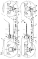
- FIG. 2 of the drawing is a partially sectioned side view Bogie frame 1 of a rail vehicle shown, on which a Eddy current brake 3 is arranged in the manner described below.
- Bogie frame 1 On each side of the vehicle is resilient on axle bearings 5 two Wheel sets supported, lifting bellows 7 connected to the bogie frame 1 act via a bracket 8 on a brake carrier 9 of the eddy current brake 3 and this from the braking position shown in FIG. 2 of the drawing into the position in FIG. 3 are able to raise the release position shown, as explained below.
- the rail brake in the present case as an example Eddy current brake shown, opposite the bogie frame 1 in the transverse direction be centered on the rail 13 with a precisely defined elasticity. Accordingly, it should be the Brake to be decoupled from the bogie in the rail plane, so to influence the running properties even positively.
- Transversely elastic centering device 21 serves this purpose.
- the upper part 23 of the centering device 21 is fixed with the bogie, that is connected to the bogie frame 1, so by means of a Holder 25.
- a according to the invention Rubber layer spring 29 mounted, so z. B. by means of a screw connection 31.
- Die Rubber layer spring 29 is constructed in multiple layers and has within certain Limits transverse elasticity; in the release position, the rubber layer spring 29 with the help the bellows 7, the bracket 8 carried by him and the bracket connected support plate 27 pressed into a centering 33 of the upper part 23.
- the Centering 33 is designed so that the rubber layer spring 29 when lifting and Entry into the upper part 23 automatically centered; as shown in Figure 1 the centering 33 is designed as a so-called chamfer.
- On top of the Rubber layer spring 29 is a thicker plate 35 vulcanized, which with the Centering 33 serves as a guide and stop.
- the rubber layer spring is selected by choosing a suitable rubber compound and the number and height of the individual layers are set so that in vertical and horizontal plane the desired (very different) Stiffness and damping values result.
- the Rubber layer spring due to elastic shear a horizontal movement between the rail brake and the bogie frame.
- the Running characteristics of the bogie positive at very high speeds affects d. H. the rail brake even acts as a vibration damper for critical ones Operating states.
- the design of the rubber layer spring is different accessible.
- Fig. are several horizontally lying Rubber layers through z. B. plates 37 connected to them by vulcanization, preferably metal plates, separated from each other.
- the layers of the rubber layers and the plates can also run at an angle, such. B. V-shaped. It is also possible that the layers have different heights.
- the centering according to the invention is not on the rail brakes shown in FIG. 2 and 3 illustrated embodiment limits d. H. it is also conventional Magnetic rail brakes applicable, in which the brake magnets in Rest the braking position on the rail. Also the construction of the bogie can differ from the illustrated embodiment.
Landscapes
- Physics & Mathematics (AREA)
- Electromagnetism (AREA)
- Engineering & Computer Science (AREA)
- Mechanical Engineering (AREA)
- Vibration Prevention Devices (AREA)
- Braking Arrangements (AREA)
- Springs (AREA)
- Platform Screen Doors And Railroad Systems (AREA)
Abstract
Description
Die Erfindung betrifft eine Aufhängung einer Schienenbremse nach dem
Gattungsbegriff des Patentanspruches 1.The invention relates to a suspension of a rail brake according to the
Generic term of
Bei einer Aufhängevorrichtung für Magnetschienenbremsen sind als pneumatische Hebe- und Senkvorrichtung sich bei Druckluftfüllung streckende Balgkörper vorgesehen; da diese Balgkörper quer zu ihrer Achse sehr weich sind, wird ein unerwünschtes Pendeln des angehobenen Schienenbremsmagneten durch in dieser Stellung (Lösestellung) in Eingriff gelangende Anschläge mit kegelmantelartigen Anschlagflächen zwischen Schienenbremsmagneten und Fahrzeugrahmen ausgeschlossen. Derartige Zentriereinrichtungen aus Kegel und Konus weisen in Lösestellung (zentrierte Stellung) eine sehr geringe Elastizität (1-2 mm), verbunden mit großer Steifigkeit, auf. Hierdurch werden die Laufeigenschaften des Drehgestells bei sehr hohen Geschwindigkeiten negativ beeinflußt.With a suspension device for magnetic rail brakes are considered pneumatic Lifting and lowering device for bellows bodies stretching when compressed air is filled intended; since these bellows bodies are very soft across their axis, a undesired swinging of the raised rail brake magnet by in this Position (release position) engaging stops with cone-shaped Stop surfaces between rail brake magnets and vehicle frame locked out. Such centering devices from cone and cone point in Release position (centered position) a very low elasticity (1-2 mm), connected with great rigidity, on. This will change the running characteristics of the bogie negatively affected at very high speeds.
Davon ausgehend besteht die Aufgabe der Erfindung darin, eine Aufhängung der in Rede stehenden Art so auszugestalten, daß die Schienenbremse in Lösestellung gegenüber dem Drehgestellrahmen in Querrichtung zur Schiene mit genau definierter Elastizität zentrierbar ist. Durch begrenzte Seitenbeweglichkeit sollen auch die Laufeigenschaften des Drehgestells von Schienenfahrzeugen bei sehr hohen Geschwindigkeiten positiv beeinflußt werden. Proceeding from this, the object of the invention is to suspend the in Specified type to design so that the rail brake in the release position compared to the bogie frame in the transverse direction to the rail with precisely defined Elasticity can be centered. Due to limited lateral mobility, the Running properties of the bogie of rail vehicles at very high Speeds are positively influenced.
Zur Lösung dieser Aufgabe dienen die Merkmale nach dem Kennzeichnungsteil des
Patentanspruches 1.To solve this problem, the features according to the labeling part of the
Die Aufhängung unter Verwendung der Gummischichtfeder vermittelt eine automatische Zentrierung, da die Gummischichtfeder entlang der Einweisefase selbsttätig in die Zentrierung einführbar ist und bündig in dieser aufgenommen wird. Durch Wahl der Schichtung und Material der Gummischichtfeder kann durch elastische Scherung eine begrenzte Horizontalbewegung zwischen der Bremse und dem Drehgestellrahmen ermöglicht werden. Hierdurch ist in gewisser Weise eine Entkoppelung der Bremse d. h. des Bremsträgers mit den an ihm angeordneten Bremsmagneten, gegenüber dem Drehgestell ermöglicht. Durch die Querbeweglichkeit wirkt die Schienenbremse bei kritischen Betriebszuständen sogar als Schwingungstilger. Die querelastische Zentrierung mit Hilfe der Gummischichtfeder ist bei Schienenbremsen beliebiger Bauart verwendbar, also sowohl bei Magnetschienenbremsen als auch bei Wirbelstrombremsen.The suspension using the rubber layer spring conveys one automatic centering, since the rubber layer spring runs along the chamfer is automatically insertable into the centering and is received flush in this. By choosing the layering and material of the rubber layer spring can by elastic shear limited horizontal movement between the brake and the bogie frame. In a way this is a Decoupling the brake d. H. of the brake carrier with the arranged on it Brake magnets, opposite the bogie. Through the The rail brake even acts sideways in critical operating conditions as a vibration absorber. The transverse elastic centering with the help of Rubber layer spring can be used for rail brakes of any type, that is both with magnetic rail brakes and with eddy current brakes.
Die Erfindung ist nachfolgend anhand eines Ausführungsbeispiels unter Bezugnahme
auf die beigefügten Zeichnung erläutert.
In Figur 2 der Zeichnung ist in teilweise geschnittener Seitenansicht ein
Drehgestellrahmen 1 eines Schienenfahrzeuges dargestellt, an welchem eine
Wirbelstrombremse 3 in nachfolgend beschriebender Weise angeordnet ist. Der
Drehgestellrahmen 1 jeweils einer Fahrzeugseite ist federnd an Achslagern 5 zweier
Radsätze abgestützt, wobei mit dem Drehgestellrahmen 1 verbundene Hebebälge 7
über einen Bügel 8 auf einen Bremsträger 9 der Wirbelstrombremse 3 einwirken und
diesen aus der in Figur 2 der Zeichnung dargestellten Bremsstellung in die in Figur 3
dargestellte Lösestellung anzuheben vermögen, wie nachfolgend erläutert ist.In Figure 2 of the drawing is a partially sectioned side view
Bogie
An der Unterseite des Bremsträgers 9 der Wirbelstrombremse befinden sich an sich
bekannte Bremsmagnete 11, welche in Bremsstellung nach Figur 2 unter einem
vorbestimmten Abstand zur schematisch wiedergegebenen Schiene 13 zu halten
sind, so z. B. unter einem Abstand von 7 mm. Für den Höhenausgleich der
Verlagerung der Wirbelstrombremse 3 zwischen den in Figur 2 und 3 dargestellten
Funktionsstellungen als auch zur Führung der Wirbelstrombremse gegenüber den
Achslagern sind an den beiden Stirnseiten des Bremsträgers 9 jeweils Arme 15
angelenkt. Jeder der Arme 15 ist zwischen seinen Enden um eine am Bremsträger
vorgesehene Achse 17 schwenkbar, wobei die sich nach außen erstreckenen Enden
der Arme 15 jeweils an einem Pendel 19 am Achslager 5 angelenkt sind. Die insoweit
beschriebene Aufhängung des Bremsträgers an den Achslagern ist nicht auf die in
Fig. 2 und 3 der Zeichnung dargestellte Ausführungsform beschränkt d. h. die Arme
15 des Bremsträgers können auch in an den Achslagern angeordneten
Lagerführungen aufliegen, wie dies nach dem Stand der Technik bekannt ist.On the underside of the
In der Lösestellung muß die Schienenbremse, im vorliegenden Fall beispielhaft als
Wirbelstrombremse dargestellt, gegenüber dem Drehgestellrahmen 1 in Querrichtung
zur Schiene 13 mit genau definierter Elastizität zentriert werden. Es soll demnach die
Bremse gegenüber dem Drehgestell in der Schienenebene entkoppelt werden, um so
die Laufeigenschaften sogar positiv zu beeinflußen. Die nachfolgend erläuterte
querelastische Zentriereinrichtung 21 dient diesem Zweck. In the release position, the rail brake, in the present case as an example
Eddy current brake shown, opposite the
Gemäß Darstellung in Figur 1 ist das Oberteil 23 der Zentriereinrichtung 21 fest mit
dem Drehgestell, also mit dem Drehgestellrahmen 1 verbunden, so mittels eines
Halters 25. Auf der Oberseite einer mit dem Bügel 8 verbundenen und am
Bremsträger 9 angebrachten Tragplatte 27 ist erfindungsgemäß eine
Gummischichtfeder 29 montiert, so z. B. mittels einer Verschraubung 31. Die
Gummischichtfeder 29 ist mehrlagig aufgebaut und besitzt innerhalb bestimmter
Grenzen Querelastizität; in der Lösestellung wird die Gummischichtfeder 29 mit Hilfe
des Hebebalgs 7, dem von ihm getragenen Bügel 8 und der mit dem Bügel
verbundenen Tragplatte 27 in eine Zentrierung 33 des Oberteils 23 gepresst. Die
Zentrierung 33 ist so ausgeführt, daß sich die Gummischichtfeder 29 beim Heben und
Einfahren in das Oberteil 23 automatisch zentriert; gemäß Darstellung in Figur 1 ist
die Zentrierung 33 als sogenannte Einweisefase ausgebildet. Auf der Oberseite der
Gummischichtfeder 29 ist eine dickere Platte 35 aufvulkanisiert, welche mit der
Zentrierung 33 als Einweiser und Anschlag dient.As shown in Figure 1, the
Die Gummischichtfeder wird durch die Wahl einer geeigneten Gummimischung und die Anzahl und Höhe der einzelnen Schichten jeweils so eingestellt, daß sich in vertikaler und horizontaler Ebene die gewünschten (stark unterschiedlichen) Steifigkeits- und Dämpfungswerte ergeben. In horizontaler Richtung kann die Gummischichtfeder durch elastische Scherung eine horizontale Bewegung zwischen der Schienenbremse und dem Drehgestellrahmen ermöglichen. Hierbei werden die Laufeigenschaften des Drehgestells bei sehr hohen Geschwindigkeiten positiv beeinflußt d. h. die Schienenbremse wirkt sogar als Schwingungstilger bei kritischen Betriebszuständen.The rubber layer spring is selected by choosing a suitable rubber compound and the number and height of the individual layers are set so that in vertical and horizontal plane the desired (very different) Stiffness and damping values result. In the horizontal direction, the Rubber layer spring due to elastic shear a horizontal movement between the rail brake and the bogie frame. Here, the Running characteristics of the bogie positive at very high speeds affects d. H. the rail brake even acts as a vibration damper for critical ones Operating states.
Die Bauart der Gummischichtfeder ist unterschiedlichen Ausführungsformen
zugängig. Bei der in Fig. dargestellten Bauvariante sind mehrere horizontal liegende
Gummischichten durch z. B. mit ihnen durch Vulkanisation verbundene Platten 37,
vorzugsweise Metallplatten, voneinander getrennt. Die Schichtungen der Gummilagen
und der Platten können jedoch auch winkelig verlaufen, so z. B. V-förmig. Es ist auch
möglich, daß die Schichten unterschiedliche Höhenmaße besitzen. The design of the rubber layer spring is different
accessible. In the construction variant shown in Fig. Are several horizontally lying
Rubber layers through z.
Die erfindungsgemäße Zentrierung ist nicht auf Schienenbremsen der in Figuren 2 und 3 dargestellten Ausführungsform beschränkt d. h. sie ist auch bei herkömmlichen Magnetschienenbremsen anwendbar, bei welchen die Bremsmagnete in Bremsstellung auf der Schiene aufliegen. Auch die Konstruktion des Drehgestells an sich kann gegenüber der dargestellten Ausführungsform unterschiedlich sein. The centering according to the invention is not on the rail brakes shown in FIG. 2 and 3 illustrated embodiment limits d. H. it is also conventional Magnetic rail brakes applicable, in which the brake magnets in Rest the braking position on the rail. Also the construction of the bogie can differ from the illustrated embodiment.
- 11
- DrehgestellrahmenBogie frame
- 33rd
- WirbelstrombremseEddy current brake
- 55
- AchslagerAxle bearing
- 77
- HebebalgBellows
- 88th
- Bügelhanger
- 99
- BremsträgerBrake carrier
- 1111
- BremsmagnetBrake magnet
- 1313
- Schienerail
- 1515
- Armpoor
- 1717th
- Achseaxis
- 1919th
- PendelPendulum
- 2121
- ZentriereinrichtungCentering device
- 2323
- OberteilTop
- 2525th
- Halterholder
- 2727
- TragplatteSupport plate
- 2929
- GummischichtfederRubber layer spring
- 3131
- VerschraubungScrew connection
- 3333
- Zentrierungcentering
- 3535
- Platteplate
- 3737
- Platteplate
Claims (7)
Applications Claiming Priority (2)
| Application Number | Priority Date | Filing Date | Title |
|---|---|---|---|
| DE19725174A DE19725174C2 (en) | 1997-06-13 | 1997-06-13 | Suspension of a rail brake on a bogie of a rail vehicle |
| DE19725174 | 1997-06-13 |
Publications (3)
| Publication Number | Publication Date |
|---|---|
| EP0884232A2 true EP0884232A2 (en) | 1998-12-16 |
| EP0884232A3 EP0884232A3 (en) | 1999-02-03 |
| EP0884232B1 EP0884232B1 (en) | 2003-09-17 |
Family
ID=7832470
Family Applications (1)
| Application Number | Title | Priority Date | Filing Date |
|---|---|---|---|
| EP98105175A Expired - Lifetime EP0884232B1 (en) | 1997-06-13 | 1998-03-23 | Suspension of a track brake to a railway vehicle bogie |
Country Status (4)
| Country | Link |
|---|---|
| EP (1) | EP0884232B1 (en) |
| AT (1) | ATE249953T1 (en) |
| DE (2) | DE19725174C2 (en) |
| ES (1) | ES2208988T3 (en) |
Cited By (2)
| Publication number | Priority date | Publication date | Assignee | Title |
|---|---|---|---|---|
| AT525629B1 (en) * | 2022-02-28 | 2023-06-15 | Siemens Mobility Austria Gmbh | Holding device for a rail vehicle brake and running gear for a rail vehicle |
| CN116710345A (en) * | 2020-12-29 | 2023-09-05 | 德商马克思博格尔两合公司 | Support Skids for Track-Constrained Suspended Vehicles |
Families Citing this family (1)
| Publication number | Priority date | Publication date | Assignee | Title |
|---|---|---|---|---|
| DE10009270B4 (en) * | 2000-02-28 | 2007-05-31 | Knorr-Bremse Systeme für Schienenfahrzeuge GmbH | Suspension for a rail brake |
Family Cites Families (5)
| Publication number | Priority date | Publication date | Assignee | Title |
|---|---|---|---|---|
| IT1032485B (en) * | 1974-04-02 | 1979-05-30 | Knorr Bremse Gmbh | DEVICE TO CENTER FRENSE MAGNETS ON TRACKS FOR VEHICLES |
| DE8416755U1 (en) * | 1984-06-01 | 1984-09-06 | Bergische Stahl-Industrie, 5630 Remscheid | CENTERING DEVICE FOR MAGNETS |
| DE4009449C2 (en) * | 1990-03-23 | 1997-08-07 | Knorr Bremse Ag | Eddy current rail brake |
| ATE164130T1 (en) * | 1995-02-02 | 1998-04-15 | Knorr Bremse Systeme | SUSPENSION OF A RAIL BRAKE, IN PARTICULAR AN EDDY CURRENT BRAKE, ON A BOGIE OF A RAIL VEHICLE |
| DE19515070C2 (en) * | 1995-04-28 | 2000-11-02 | Knorr Bremse Systeme | Linear eddy current brake |
-
1997
- 1997-06-13 DE DE19725174A patent/DE19725174C2/en not_active Expired - Fee Related
-
1998
- 1998-03-23 DE DE59809615T patent/DE59809615D1/en not_active Expired - Lifetime
- 1998-03-23 EP EP98105175A patent/EP0884232B1/en not_active Expired - Lifetime
- 1998-03-23 ES ES98105175T patent/ES2208988T3/en not_active Expired - Lifetime
- 1998-03-23 AT AT98105175T patent/ATE249953T1/en active
Non-Patent Citations (1)
| Title |
|---|
| None |
Cited By (5)
| Publication number | Priority date | Publication date | Assignee | Title |
|---|---|---|---|---|
| CN116710345A (en) * | 2020-12-29 | 2023-09-05 | 德商马克思博格尔两合公司 | Support Skids for Track-Constrained Suspended Vehicles |
| CN116710345B (en) * | 2020-12-29 | 2026-03-10 | 四川发展磁浮科技有限公司 | Support skid for track-bound levitation vehicle |
| AT525629B1 (en) * | 2022-02-28 | 2023-06-15 | Siemens Mobility Austria Gmbh | Holding device for a rail vehicle brake and running gear for a rail vehicle |
| AT525629A4 (en) * | 2022-02-28 | 2023-06-15 | Siemens Mobility Austria Gmbh | Holding device for a rail vehicle brake and running gear for a rail vehicle |
| EP4234344A1 (en) * | 2022-02-28 | 2023-08-30 | Siemens Mobility Austria GmbH | Holding device for a rail vehicle brake and chassis for a rail vehicle |
Also Published As
| Publication number | Publication date |
|---|---|
| DE19725174C2 (en) | 1999-08-12 |
| DE59809615D1 (en) | 2003-10-23 |
| EP0884232B1 (en) | 2003-09-17 |
| ES2208988T3 (en) | 2004-06-16 |
| EP0884232A3 (en) | 1999-02-03 |
| DE19725174A1 (en) | 1998-12-24 |
| ATE249953T1 (en) | 2003-10-15 |
Similar Documents
| Publication | Publication Date | Title |
|---|---|---|
| DE69607518T2 (en) | Bogie with variable track width for railways | |
| EP0393177A1 (en) | Tilt compensator for high-speed vehicles, in particular rail vehicles. | |
| DE2255254B2 (en) | Suspension device for a linear inductor on the bogie of a rail vehicle | |
| EP0282796B1 (en) | Point for switches or crossings | |
| EP0218897A2 (en) | Running gear support for aerial cableways, especially for closed-loop single-cable cableways | |
| EP0884232B1 (en) | Suspension of a track brake to a railway vehicle bogie | |
| DE8911037U1 (en) | Chassis for rail-guided showman vehicles | |
| EP1572516B1 (en) | Running gear for rail vehicles | |
| EP0290930B1 (en) | Railway system for operating a derailing proof high speed railway vehicle | |
| DE937959C (en) | Suspension of cradle-less bogies of rail vehicles | |
| AT390422B (en) | LIFTING AND LOWERING STATION FOR RAILWAYS | |
| EP1057707A1 (en) | Railway vehicle bogie | |
| EP0447771B1 (en) | Eddy current rail track brake | |
| EP0724997B1 (en) | Suspension of a track brake, especially an eddy current brake on a bagie of a rail vehicle | |
| CH616625A5 (en) | Device for guiding a bogie of a rail vehicle on the underframe of a wagon body | |
| EP3793879B1 (en) | Wheel set intermediate frame for a rail vehicle | |
| DE19503381C2 (en) | Suspension of a rail brake on a bogie of a rail vehicle | |
| EP1272382B1 (en) | Suspension for a rail brake | |
| EP4370399B1 (en) | Running gear for a rail vehicle, comprising a magnetic rail brake and a centring device, magnetic rail brake and centring device | |
| DE102017009094A1 (en) | Floor conveyor and method of transport on a floor conveyor | |
| DE102013224933B4 (en) | Device for guiding a wheel set in the running gear of a rail vehicle | |
| DE102008053227A1 (en) | Piston/cylinder unit fastening arrangement for pneumatic and/or hydraulic compensation of weight-force of sleeve of e.g. coordinate measuring device, has compensation device held on support structure and/or connected with support structure | |
| EP0299318A2 (en) | Undercarriage for railway vehicles with magnetic track brake or eddy current brake | |
| DE473571C (en) | Device for guiding high-speed railways in vertical hanging positions, especially on stations | |
| DE102005004721B4 (en) | Connection to a bogie of a rail vehicle |
Legal Events
| Date | Code | Title | Description |
|---|---|---|---|
| PUAI | Public reference made under article 153(3) epc to a published international application that has entered the european phase |
Free format text: ORIGINAL CODE: 0009012 |
|
| AK | Designated contracting states |
Kind code of ref document: A2 Designated state(s): AT CH DE ES FR GB IT LI SE |
|
| AX | Request for extension of the european patent |
Free format text: AL;LT;LV;MK;RO;SI |
|
| PUAL | Search report despatched |
Free format text: ORIGINAL CODE: 0009013 |
|
| AK | Designated contracting states |
Kind code of ref document: A3 Designated state(s): AT BE CH DE DK ES FI FR GB GR IE IT LI LU MC NL PT SE |
|
| AX | Request for extension of the european patent |
Free format text: AL;LT;LV;MK;RO;SI |
|
| 17P | Request for examination filed |
Effective date: 19990224 |
|
| AKX | Designation fees paid |
Free format text: AT CH DE ES FR GB IT LI SE |
|
| 17Q | First examination report despatched |
Effective date: 20020603 |
|
| GRAH | Despatch of communication of intention to grant a patent |
Free format text: ORIGINAL CODE: EPIDOS IGRA |
|
| GRAS | Grant fee paid |
Free format text: ORIGINAL CODE: EPIDOSNIGR3 |
|
| GRAA | (expected) grant |
Free format text: ORIGINAL CODE: 0009210 |
|
| AK | Designated contracting states |
Kind code of ref document: B1 Designated state(s): AT CH DE ES FR GB IT LI SE |
|
| PG25 | Lapsed in a contracting state [announced via postgrant information from national office to epo] |
Ref country code: GB Free format text: LAPSE BECAUSE OF FAILURE TO SUBMIT A TRANSLATION OF THE DESCRIPTION OR TO PAY THE FEE WITHIN THE PRESCRIBED TIME-LIMIT Effective date: 20030917 |
|
| REG | Reference to a national code |
Ref country code: GB Ref legal event code: FG4D Free format text: NOT ENGLISH |
|
| REG | Reference to a national code |
Ref country code: CH Ref legal event code: EP |
|
| REF | Corresponds to: |
Ref document number: 59809615 Country of ref document: DE Date of ref document: 20031023 Kind code of ref document: P |
|
| RIN2 | Information on inventor provided after grant (corrected) |
Inventor name: ELSTORPFF, MARC, DR. Inventor name: GRAF, THOMAS |
|
| PG25 | Lapsed in a contracting state [announced via postgrant information from national office to epo] |
Ref country code: SE Free format text: LAPSE BECAUSE OF FAILURE TO SUBMIT A TRANSLATION OF THE DESCRIPTION OR TO PAY THE FEE WITHIN THE PRESCRIBED TIME-LIMIT Effective date: 20031217 |
|
| GBV | Gb: ep patent (uk) treated as always having been void in accordance with gb section 77(7)/1977 [no translation filed] |
Effective date: 20030917 |
|
| PG25 | Lapsed in a contracting state [announced via postgrant information from national office to epo] |
Ref country code: LI Free format text: LAPSE BECAUSE OF NON-PAYMENT OF DUE FEES Effective date: 20040331 Ref country code: CH Free format text: LAPSE BECAUSE OF NON-PAYMENT OF DUE FEES Effective date: 20040331 |
|
| REG | Reference to a national code |
Ref country code: ES Ref legal event code: FG2A Ref document number: 2208988 Country of ref document: ES Kind code of ref document: T3 |
|
| PLBQ | Unpublished change to opponent data |
Free format text: ORIGINAL CODE: EPIDOS OPPO |
|
| PLBI | Opposition filed |
Free format text: ORIGINAL CODE: 0009260 |
|
| ET | Fr: translation filed | ||
| PLAZ | Examination of admissibility of opposition: despatch of communication + time limit |
Free format text: ORIGINAL CODE: EPIDOSNOPE2 |
|
| PLAX | Notice of opposition and request to file observation + time limit sent |
Free format text: ORIGINAL CODE: EPIDOSNOBS2 |
|
| PLBA | Examination of admissibility of opposition: reply received |
Free format text: ORIGINAL CODE: EPIDOSNOPE4 |
|
| 26 | Opposition filed |
Opponent name: SIEMENS AKTIENGESELLSCHAFT OESTERREICH Effective date: 20040616 |
|
| REG | Reference to a national code |
Ref country code: CH Ref legal event code: PL |
|
| PLAX | Notice of opposition and request to file observation + time limit sent |
Free format text: ORIGINAL CODE: EPIDOSNOBS2 |
|
| PLBB | Reply of patent proprietor to notice(s) of opposition received |
Free format text: ORIGINAL CODE: EPIDOSNOBS3 |
|
| PLBP | Opposition withdrawn |
Free format text: ORIGINAL CODE: 0009264 |
|
| PLBD | Termination of opposition procedure: decision despatched |
Free format text: ORIGINAL CODE: EPIDOSNOPC1 |
|
| PLBM | Termination of opposition procedure: date of legal effect published |
Free format text: ORIGINAL CODE: 0009276 |
|
| STAA | Information on the status of an ep patent application or granted ep patent |
Free format text: STATUS: OPPOSITION PROCEDURE CLOSED |
|
| 27C | Opposition proceedings terminated |
Effective date: 20061021 |
|
| PGFP | Annual fee paid to national office [announced via postgrant information from national office to epo] |
Ref country code: IT Payment date: 20120327 Year of fee payment: 15 |
|
| PG25 | Lapsed in a contracting state [announced via postgrant information from national office to epo] |
Ref country code: IT Free format text: LAPSE BECAUSE OF NON-PAYMENT OF DUE FEES Effective date: 20130323 |
|
| REG | Reference to a national code |
Ref country code: FR Ref legal event code: PLFP Year of fee payment: 19 |
|
| PGFP | Annual fee paid to national office [announced via postgrant information from national office to epo] |
Ref country code: DE Payment date: 20160322 Year of fee payment: 19 Ref country code: ES Payment date: 20160322 Year of fee payment: 19 |
|
| PGFP | Annual fee paid to national office [announced via postgrant information from national office to epo] |
Ref country code: AT Payment date: 20160318 Year of fee payment: 19 Ref country code: FR Payment date: 20160322 Year of fee payment: 19 |
|
| REG | Reference to a national code |
Ref country code: DE Ref legal event code: R119 Ref document number: 59809615 Country of ref document: DE |
|
| REG | Reference to a national code |
Ref country code: AT Ref legal event code: MM01 Ref document number: 249953 Country of ref document: AT Kind code of ref document: T Effective date: 20170323 |
|
| REG | Reference to a national code |
Ref country code: FR Ref legal event code: ST Effective date: 20171130 |
|
| PG25 | Lapsed in a contracting state [announced via postgrant information from national office to epo] |
Ref country code: AT Free format text: LAPSE BECAUSE OF NON-PAYMENT OF DUE FEES Effective date: 20170323 Ref country code: DE Free format text: LAPSE BECAUSE OF NON-PAYMENT OF DUE FEES Effective date: 20171003 Ref country code: FR Free format text: LAPSE BECAUSE OF NON-PAYMENT OF DUE FEES Effective date: 20170331 |
|
| REG | Reference to a national code |
Ref country code: ES Ref legal event code: FD2A Effective date: 20180507 |
|
| PG25 | Lapsed in a contracting state [announced via postgrant information from national office to epo] |
Ref country code: ES Free format text: LAPSE BECAUSE OF NON-PAYMENT OF DUE FEES Effective date: 20170324 |